[Corrected and revised version of original paper published in Applied Optics, Vol. 27, No. 10, May 15, 1988. The author is now with Pacific-Sierra Research Corporation, 1400 Key Blvd., Suite 700, Arlington VA, 22209.]
Mark J. Carlotto
The Analytic Sciences Corporation (TASC)
55 Walkers Brook Drive
Reading, MA 01867
Initial criticism of their work centered on the human tendency to find faces everywhere; in other words, finding a feature which resembles a humanoid face in isolation on Mars tells us nothing. However, in a subsequent investigation motivated by the work of DiPietro and Molenaar, other nearby objects which seemed to be related to the Face were found. In particular, the Face appeared to be aligned with a collection of polyhedral objects to the southwest, termed the ‘City,’ which did not appear to fit the underlying geology of this part of Cydonia. Hoagland, a member of the investigation team, went on to show that solstice alignments between the Face and certain objects in the City are satisfied every million years, the last one being about a half a million years ago. Others speculated that the City and Face were near the shoreline of an ancient northern sea. Their results were presented at the 1984 Case for Mars Conference [2]. Critics claimed that such objects could not possibly occur on Mars because life, let alone an intelligence capable of creating such things, could not have developed on Mars based on current theories.
In support of more recent work [3,4,5], further analysis of the available orbiter imagery using image processing and computer graphics techniques has been performed in order to obtain the best possible enhancements of these objects, and to determine the underlying 3-D structure of the Face. Once the 3-D shape has been derived questions such as: "What does it look like when viewed under different illumination conditions and from different perspectives?", or "Does the underlying 3-D structure also resemble a face, or is the impression of a face merely a trick of light and shadow?" can be answered.
The organization of the remainder of this paper is as follows: Section II reviews the imagery and data that were made available for the study. Image enhancement results of the Face and other nearby objects are presented in Section III. Section IV addresses the problem of deriving 3-D information from the available imagery. 3-D reconstructions of the Face obtained using a single image shape-from-shading technique are presented. The 3-D information is then used to synthesize alternative views under varying illumination conditions and from different perspectives. Results are summarized in Section V.
The Face and other nearby objects are located in the region of Mars known as Cydonia Mensae. The region of interest is in the northern portion of Cydonia Mensae bordering Acidalia Planitia and the northern plains. It is a region containing a variety of flat-topped prominences with cliff-like walls (mesas) and conical hills or knobs. The geology of this and other parts of Cydonia Mensae are described by Guest and Butterworth [6]. Mesas are 5-10 km wide and are thought to be remnants of cratered plateau material that was subsequent stripped back by erosional processes. Knobs are smaller, about 2 km across, and might be isolated hills with a shallow apron around the base or be on top of mesas. No single mechanism has been suggested for their origin. Geologically, the Face would be considered to be a knob.
The Face is located at approximately 40.9° N 9.45° W. Four images containing the Face have been identified and were made available for the study:
The above images are referenced in terms of their picture number where 35A72 is the 72nd image taken in the 35th orbit by the A spacecraft. Frames 35A72 and 70A13 were acquired near periapsis with the spacecraft about 1500 km from the planet; the latter two frames were acquired near apoapses (about 33,000 km) when the orbit was shifted for synoptic coverage. Thus, only the first two scenes have sufficent resolution (approximately 50 meters/pixel) for our analysis. The second two were useful in that they provided a context for our analysis. Table I summarizes relevant imaging parameters for the two higher resolution images. This information was obtained from the Science Data Block [7].
Although the planet was viewed under a variety of illumination conditions, only two higher resolution views of the Face, both under similar illumination conditions and perspective were acquired. No higher resolution images of the Face in morning light appear to exist. Thus only the features on the left, sunlit side of the Face are visible. The following sections describe our efforts to enhance subtle features on the right, shadowed side of the Face, to reconstruct the 3-D structure of the Face using the method of shape-from-shading, and to generate synthetic views of the Face under varying illumination conditions and perspective from the 3-D model.
The raw Viking imagery contained a great deal of "salt-and- pepper" noise caused by datatransmission errors. The first step was to "clean up" the imagery by a non-linear noise removal technique which used a Laplacian filter to detect outliers (i.e., pixels whose values differ from the local mean by more than a specified threshold) and a median filter to replace the value of outliers by their local median. The threshold was manually selected to reduce the magnitude of the noise without significantly distorting the fine-scale detail in the image. For visual interpretation, the images were enhanced using a local contrast stretch algorithm [8] which computes the output pixel o(m, n) at the center of an MxN window that is slid over the input image i(m,n) according to
where (m,n) is the local mean computed in the MxN window centered at pixel (m,n), g is the local gain or stretch factor, and
 is the local mean preservation factor. The parameter values, M = N = 65, g = 5, and
=1 were selected to remove global shading variations due to illumination and albedo variations across the imagery, and to increase the local constrast while maintaining the overall tonal balance of the imagery.
Fig. 1 is a restored and contrast enhanced subscene from 35A72. The image contains the Face and a collection of polyhedral structures to thesouthwest (the City). Objects and their shadows, as well as subtle variations in the surrounding terrain due to albedo and topographic variation have been enhanced. The circular ring in the center of the photo is a blemish on the vidicon. Remnants of reseau marks that were not completely removed by the restoration can also be seen.
is the local mean preservation factor. The parameter values, M = N = 65, g = 5, and
=1 were selected to remove global shading variations due to illumination and albedo variations across the imagery, and to increase the local constrast while maintaining the overall tonal balance of the imagery.
Fig. 1 is a restored and contrast enhanced subscene from 35A72. The image contains the Face and a collection of polyhedral structures to thesouthwest (the City). Objects and their shadows, as well as subtle variations in the surrounding terrain due to albedo and topographic variation have been enhanced. The circular ring in the center of the photo is a blemish on the vidicon. Remnants of reseau marks that were not completely removed by the restoration can also be seen.
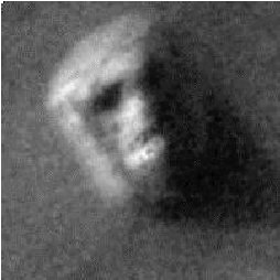
Fig. 2 shows two enhanced views of the Face from 35A72 (a) and 70A13 (b). The images were registered to one another via a first order polynomial transformation and magnified by a factor of four using a cubic spline interpolation technique. Lack of sufficient parallax due to the imaging geometry prevents the extraction of 3-D information from the imagery by the method of stereoscopy (discussed in Section IV). However, common features are apparent in the two images including what some have interpreted to be "teeth" and symmetrical lines or cracks across the forehead. These features cannot be dismissed as noise in the imagery or artifacts of the processing since they appear in both images.
Fig. 3 is another contrast stretch of the Face in 70A13 that enhances subtle features on its partially shadowed right side. A smaller window size M = N = 17 to enhance smaller scale features, and a larger gain and lower mean preservation factor (g = 50 and = 0.5 ) to bring out subtle shading variations in the shadow, were used. What appears to be the extension of the mouth and possibly a second eye socket may be seen. These results are similar to those obtained by DiPietro and Molenaar [1].
As provocative as the above enhancements may be, they are not sufficient in themselves; i.e., a feature which resembles a face in isolation tells us nothing. Hoagland [2] has suggested however that the Face appears to fit into a broader context. In particular, the Face seems to be aligned with a collection of objects in the City (see Fig. 1). The ensemble of objects in the City includes a five sided pyramid and an extremely unusual trapezoidal object measuring about 2 km across which resembles a fortress. Fig. 4 is a constrast enhancement of the ‘Fortress’ and shows four straight sides or walls enclosing an inner space. Two of the walls appear to contain regularly spaced markings or indentations. The black mark to the right of the northeastern wall is the remnant of a reseau mark that was incompletely removed by the restoration algorithm. The close proximity of unusual objects such as these to the Face increases the likelihood that this collection of objects is not natural.
This section begins by reviewing methods for recovering 3-D information from imagery. The method of shape-from-shading which was chosen is then described and assumptions made in applying the technique to orbiter images 35A72 and 70A13 are stated. The 3-D reconstructions obtained from both images are presented next. Synthetic images are then generated from the 3-D model under varying light source positions and perspectives to show that the impression of facial features evident in 35A72 and 70A13 is not a transient phenomenon.
A. Methods for Recovering 3-D Information
The recovery of 3-D information from one or more image can be approached in a variety of ways depending on the available imagery: by the analysis of the heights of shadows, by stereoscopy, or by shape-from-shading (also known as photoclinometry).
Shadow analysis involves relating the lengths of shadows to the heights of objects casting the shadows and is only able to reconstruct the silhouette of the shadow-casting object. By measuring the lengths of the shadows in 35A72 and 70A13, the peak height of the Face was found to be approximately 400 meters using the values of the zenith angle given in the Science Data Block. This value is close to the values estimated later in this section by the shape-from-shading algorithm and thus corroborates the metric accuracy of the 3-D reconstructions.
Stereo matching techniques [9] involve matching features in one image of a stereo pair to the corresponding feature in the other image in order to determine their heights. Stereo matching techniques are preferred when there are many distinct features such as edges to match and when the stereo pair exhibits sufficient parallax. The angle between the orbiter positions in 35A72 and 70A13 is, from spherical trigonometry,
for the values given in Science Data Block. The above yields a baseline distance between orbiter
positions of

where R0 and R1 , 0 and
1, and
0 and
1, and
 0 and
1 are the ranges, zenith angles and azimuth angles of the orbiter in 35A72 and 70A13 respectively (see
Table I). Using the camera model described in Sloma [10] for opposite side stereoscopy, the resolvable height is
0 and
1 are the ranges, zenith angles and azimuth angles of the orbiter in 35A72 and 70A13 respectively (see
Table I). Using the camera model described in Sloma [10] for opposite side stereoscopy, the resolvable height is
 z =
x(2H / B) where H = (R0 + R1) / 2 and
x is the ground resolution. The minimum height resolvable by the system is approximately 772 meters which is greater than the peak height of the Face. Thus stereoscopy is not useful for recovering 3-D information from the available imagery.
z =
x(2H / B) where H = (R0 + R1) / 2 and
x is the ground resolution. The minimum height resolvable by the system is approximately 772 meters which is greater than the peak height of the Face. Thus stereoscopy is not useful for recovering 3-D information from the available imagery.
Shape-from-shading techniques include the recovery of surface orientation from a single image [11], and from two or more images under different lighting conditions (photometric stereo) [12]. The recovery of shape information from a single image is also known as photoclinometry in the planetary science community. Shape-from-shading techniques reconstruct the shape of the object being imaged by relating shading information to surface orientation. In cases where there is a lack of distinct surface features and texture, and the primary source of shape information is shading, shape-from- shading (photoclinometric) methods are preferred over stereoscopy. It has been noted that Mars is especially well-suited for photoclinometry since the winds tend to redeposit materials uniformly over the surface so that surface material properties are fairly homogeneous within the same geological province [13].
B. Shape-from-shading
When the vertical relief of a scene is small compared to the distance to the spacecraft and the camera has a narrow field of view (conditions met for the Viking imagery), the imaging geometry can be approximated by an orthographic projection. In an orthographic projection, rays travel from the scene to the image plane along parallel lines. Under these conditions the irradiance E(x, y) of a point in the image plane is proportional to the radiance L(x, y) of the point on the scene surface and is given by:

where k is a constant that represents the effects of the imaging system, is the albedo of the surface, E0 is the irradiance of the illuminant, and R(p, q) is the reflectance map. Information concerning the position of the viewer and light source(s) and the scattering properties of the surface material is contained in the reflectance map where p =
 z /
x and q =
z /
y are the surface gradients in the x and y directions, respectively. When all quantities on the right side are known, the left side can be computed directly as is done in computer graphics for producing shaded renditions of surfaces. However, the inverse problem is underdetermined since there are many gradients which will give rise to a particular irradiance.
z /
x and q =
z /
y are the surface gradients in the x and y directions, respectively. When all quantities on the right side are known, the left side can be computed directly as is done in computer graphics for producing shaded renditions of surfaces. However, the inverse problem is underdetermined since there are many gradients which will give rise to a particular irradiance.
A relatively simple but elegant method for estimating the gradients is by the method of photometric stereo when two or more images of the scene are available from the same perspective but under different lighting conditions [11,12]. As determined earlier, the two orbiter images are 6.08° apart in view angle; from the Science data block one can readily calculate that they are 23.75° apart in sun angle. Thus, the orbiter geometry is better suited for photometric stereo than for stereoscopy. The method of photometric stereo, which was originally developed for relatively low noise industrial machine vision environments, is, unfortunately, very sensitive to noise. Experiments were conducted on both simulated imagery with lighting conditions and noise levels similar to 35A72 and 70A13 and on the actual imagery to assess its usefulness. The resultant gradient fields were noisy and strongly inconsistent; i.e., not readily integratable into elevation surfaces. It was thus concluded that the method of photometric stereo is also not useful for recovering 3-D information from the available imagery.
Finally, we turn to single image shape-from-shading methods. The recovery of shape from a single image is computationally more difficult because we are trying to determine a gradient field with two degrees of freedom from an image which has only one degree of freedom. Various methods have been developed in both the planetary science and the machine vision communities to solve this problem [11,14]. In the planetary community, single image shape-from-shading is known as photoclinometry, a term coined by McCauley in 1965. The method used here was adopted from Strat [15] and Terzoupolis [16] and is based on an iterative multi-resolution approach [17]. The height map z(x, y) is computed from a single image E(x, y) in two steps by first estimating the gradients from the image irradiances via the reflectance map and then determining the elevations from the gradients. The iterative approach to shape-from-shading is to be contrasted with those methods which attempt to compute the elevation surface by direct integration of the brightness gradients [13,14]. They, like the method of photometric stereo are sensitive to image noise and may produce inconsistent gradient fields.
The gradient field (p,q) is estimated by an iterative algorithm which seeks to minimize the integral

where py =
p /
y and qx =
q /
x . The first term is the difference between the actual and estimated irradiances. The second term forces the gradients to be consistent, i.e., to correspond to a real elevation surface, and also provides a built in immunity to noise. Solution methods for the above equation are discussed in Horn [11]. If pij and qij are the sample values of the gradients at the grid point (i, j) , the form of the solution is
where Cp and Cq are linear combinations of the values of p and q in the neighborhood around (i, j) , Rp = R /
p, and Rq =
R /
q ; the initial conditions are pij(0) = 0 and qij(0) = 0.
In the above algorithm, a penalty term is added to force the gradient field to be consistent. Since consistency is not enforced as a strict constraint, the resultant gradients will be somewhat inconsistent and so cannot be directly integrated into an elevation surface. Therefore, the elevation map z(x, y) is computed by another iterative algorithm which minimizes the integral:
where zx = z /
x and zy =
z /
y .
The algorithm used here assumes a flat background as a boundary condition. Other shape-fromshading algorithms use different boundary conditions such as occluding boundaries, or in photoclinometry, planetary limbs. The algorithm also forces the reconstructed surface to follow the grazing rays of the sun in shadowed areas. This provides an implicit boundary condition that in turn forces the lengths of shadows to agree with the heights of the objects casting the shadows.
C. Imaging Model
Before applying the shape-from-shading algorithm to the imagery, the salient characteristics of the atmosphere, the imaged surface, and the illumination must be considered. In addition to the orthographic imaging assumption stated earlier, five additional assumptions are made:
The first assumption allows us to reduce a 3-D problem to a 1-D problem [18]. Assumption two is based on observations by Wildey [13] that the winds tend to redeposit surface materials in a uniform fashion so the albedo and scattering properties can be treated as approximately constant over small areas. Assumption three was made in lieu of specific knowledge about the composition of surface materials in Cydonia. The paucity of imagery over the region of interest precluded an empirical estimation of the reflectance map (photometric function) via a Minneart or Lommel- Seeliger fit, for example. The results presented in the next section show that, to a first order, the Lambertian is a good model over the region of interest. The point source and hemispherical sky assumptions are made to simplify the reflectance map. To check the validity of the point source assumption, the sun was modeled as an extended source (0.34° at Mars) and found to have negligible effect on the surface reconstruction. The hemispherical sky term is used to model ambient light (more on this below). Finally, the last assumption allows image intensities to be converted into normalized reflectances between zero and one for shape-from-shading and supplies the needed boundary condition.
The resultant image formation model (adapted from Sjoberg [18]) is given by:

where L(x, y) is the radiance, is the albedo, Tu (z) is the vertical atmospheric transmittance fromaltitude z up to the spacecraft, E0 is the extra-terrrestrial solar irradiance, Td(z) is the path transmittance from the sun to altitude z , R(p, q) is the reflectance map for a Lambertian scatterer illuminated by a point source, Es (z) is the sky irradiance at altitude z , Ra(p,q) is the reflectance map for a Lambertian scatterer under a uniform hemispherical source, and Lp(z) is the path radiance between the spacecraft and the surface at altitude z . Since the field of view is small, and the variation in altitude is small relative to the depth of the atmosphere within the field of view, we treat Tu(z), Td(z), Es (z), and Lp(z) as constants. The low digital counts in the shadows suggest that E0Td (z) >> Es (z) and that the contribution of the Lp(z) term on the right side is small (but not zero). However, given the limited dynamic range of the data and the relatively high noise level, we shall assume that it is negligable and, for the present, shall concern ourselves with the portion of the Face that is directly illuminated by the sun.
Assuming an orthographic imaging model, the previous equation can be simplified as
where k1 and k2 are constants. Assuming a linear relationship between the image irradiance E(x, y) and the digital image intensity data I(x, y), image intensities and reflectances can be related by

Imax is assumed to correspond to areas that face the sun ( R = 1) and Imin is assumed to correspond to areas in shadow (R = 0). Finally, the reflectance map for a Lambertian surface illuminated by a point source at (p0 ,q0 ) is given by:
where p0 = tan 0 cos(90 +
0 ) and q0 = tan
0 sin(90 +
0 ) . The angle
is measured relative from the zenith and the azimuth angle
is measured clockwise from north. Values of p0 and q0 for 35A72 and 70A13 are derived from the ephemeris data in
Table I.
D. Results
Reconstructions of the Face were computed from 35A72 and 70A13 using the single image shapefrom-shading algorithm. An isometric plot of the elevation map computed from 70A13 is shown in Fig. 5. The view is from the northwest, i.e., above and to the left of the of the Face. An almost identical result was obtained from 35A72. Both results clearly show evidence of facial features in the underlying topography. The reconstructed shape of the Face appears somewhat smoother than one would expect from looking at the imagery since the area is rather small to begin with (64x64 pixels total), derivatives are estimated locally within 3x3 windows, and the presence of the consistency constraint in the iterative formulation has the effect of trading off detail for reduced noise.
To check the validity of the results, synthetic images were computed from the gradient fields of the reconstructed surfaces and compared to the original data. Figures 6a and b are the original images from 35A72 and 70A13. Figures 6c and d are the synthetic images obtained by illuminating the 3- D surface reconstructed from 35A72 with the light source at positions corresponding to 35A72 and 70A13, respectively. Figures 6e and f are the synthetic images obtained by illuminating the 3-D surface computed from 70A13 with the light source at positions corresponding to 35A72 and 70A13, respectively. The close agreement between a, c and e, and b, d and f suggests that the Lambertian model assumption is adequate given the quality of the data.
Synthetic images of how the 3-D surface might appear under different illumination conditions are shown in Fig. 7. The images in the figure were generated by substituting the gradients estimated by the shape-from-shading algorithm into the reflectance map equation for different light source positions. The facial features evident in the original orbiter photographs are also present under different illumination conditions. Under simulated morning light, the left side of the Face is dark and the left eye is bright while in afternoon light the situation is reversed.
To simulate the appearence of the Face from differenct perspectives, the image of the Face from 35A72 was projected onto the elevation map computed above and reprojected using a computer graphics rendering system. The renderer can generate perspective views of 3-D scenes for arbitrary camera positions. In this case the 3-D scene was the image in 35A72 projected onto the 3-D surface computed by the shape-from-shading algorithm. Simulated images for different positions around the Face are shown in Fig. 8. Again, the facial features evident in the down-looking view of the orbiter photography are also present when the object is viewed from radically different perspectives. Such is not the case in more familiar terrestrial analogs such as New Hampshire's Old Man of the Mountain, for example.
Finally measusrements of the peak height, length, width, and maximum slope of the feature weremade for both 3-D surfaces. The peak height was corroborated by measuring the length of the shadows. In general, the results presented in Table II show good agreement between the two images.
V. Summary and Conclusions
Digital image enhancements of a mile long feature resembling a humanoid face and other nearbyobjects in the Cydonia region of Mars were performed, the 3-D structure of the Face was derived using a single image shape-from-shading algorithm, and synthetic views were then generated using computer graphics techniques. The 3-d analysis was performed because there is a lack of high resolution images of this area viewed under conditions other than in afternoon light and from directly overhead. The intent was to create synthetic views of the Face to determine if the visual impression of a face perists over a wide range of lighting conditions and perspectives.
The image enhancement results indicate that a second eye socket may be present on the right, shadowed side of the Face. Fine structure in the mouth suggesting teeth are apparent in the enhanced imagery as well as crossed symmetrical lines on the forehead. The results of the 3-d analysis show that the impression of facial features is not a transient phenomenon. Facial features are evident in the underlying topography and are shown to induce the visual impression of a face over a wide range of illumination conditions and perspectives.
It is the author's belief that although the Viking data are not of sufficient resolution to permit the identification of possible mechanisms of origin for these objects, the results to date suggest that they may not be natural. At the very least, these enigmatic objects deserve further scrutiny by future Mars probes such as the 1988 Soviet Phobos mission or the U.S. Mars Observer.
2. Hoagland, "Preliminary Report of the Independent Mars Investigation Team: New Evidence of Prior Habitation?," presented at Case for Mars II Conference , July, 1984, Boulder, CO, 1984.
3. Pozos, The Face on Mars: Evidence for a Lost Civilization? , Chicago Review Press, Chicago, IL, 1986.
4. Grossinger, "The Face on Mars: An Interview with Richard Hoagland," in Planetary Mysteries , North Atlantic Books, Berkeley, CA, 1986.
5. Hoagland, The Monuments of Mars , North Atlantic Books, Berkeley, CA, 1987.
6. Guest and P. S. Butterworth, "Geological Observations in the Cydonia Region of Mars from Viking," Journal of Geophysical Research , Vol. 82, No. 28, Sept 30, 1977.
7. Carr, The Surface of Mars , Yale University Press, New Haven and London, 1981.
8. Tom, "Adaptive Filter Techniques for Digital Image Enhancement," SPIE Digital Image Processing: Critical Review of Technology , Los Angeles, CA, January, 1985.
9. Grimson, From Images to Surfaces , MIT Press, Cambridge, MA, 1981.
10. Sloma (ed.), Manual of Photogrammetry , American Society of Photogrammetry, 9th Edition, 1980.
11. Horn, Robot Vision , MIT Press, Cambridge MA, 1986.
12. Woodham, "Photometric Method for Determining Surface Orientation from Multiple Images," Optical Engineering , Vol. 19, No. 1, January, 1980.
13. Wildey, "Generalized Photoclinometry for Mariner 9," ICARUS , Vol. 25, pp 613-626, 1975.
14. Rindfleisch, "Photometric Method for Lunar Topography," Photogrammetric Engineering , Vol. 32, No. 2, March, 1966.
15. Strat, "A Numerical Method for Shape from Shading from a Single Image," S.M. Thesis, Dept. of EE&CS, MIT, Cambridge, MA, January, 1979.
16. Terzopoulis, "Computing Visible-Surface Representations," Memo AIM-800, MITArtificial Intelligence Lab, March, 1985.
17. Van Hove and M. Carlotto, "An Iterative Multi-Resolution Shape-from-Shading Algorithmand its Application to Planetary Mapping," International Geoscience and Remote SensingSymposium , Zurich, Switzerland, September, 1986.
18. Sjoberg, "Atmospheric Effects in Satellite Imaging of Mountainous Terrain," TR-688, MIT Artificial Intelligence Lab., Cambridge, MA, Sept, 1982.
† Parameters referenced in Science Data Block.


Digital Imagery Analysis of Unusual Martian Surface Features
Mark J. Carlotto
The Analytic Sciences Corporation (TASC)
55 Walkers Brook Drive
Reading, MA 01867
Abstract
Image processing results in support of on-going research into the origin of a collection of unusual surface features on Mars are presented. The focus of the investigation is on a mile long feature in the Cydonia region of Mars which resembles a humanoid face that was imaged by Viking orbiter in 1976. While the ‘Face’ has been dismissed as a trick of light and shadow by some, there remains considerable interest in this feature, which others believe was sculpted into the form of a humanoid face, and several nearby polyhedral objects which appear to be spatially aligned with it. Image enhancements of the Face show it to be a bisymmetrical object having two eyes, a nose, and a mouth; fine structure in the mouth suggesting teeth are apparent in the enhanced imagery as well as crossed symmetrical lines on the forehead. Facial features are also evident in the underlying 3-D surface which was reconstructed using a single image shape-from-shading technique. Synthetic images derived from the 3-D model by computer graphics techniques suggest that the impression of "facial features" evident in the original Viking imagery are not a transient phenomenon; i.e., they persist over a wide range of illumination and viewing conditions.I. Introduction
In July of 1976, the Viking Orbiter acquired a strange image of what appeared to be a face staring straight up into space from the surface of Mars. The ‘Face’ was in a region known as Cydonia in Mars' northern hemisphere, originally selected as a possible landing site for Viking. Officially dismissed at the time as a "trick of light and shadow", the Face was rediscovered by DiPietro and Molenaar, engineers at the Goddard Space Flight Center, several years later. During the course of their investigation, a second image of the Face that had been acquired under slightly different lighting conditions was found. Digital image enhancements of this second image revealed a bisymmetrical object having features suggestive of eyes, a ridge-like nose, and a mouth. Due to the controversial nature of the subject, their results were published independently of the planetary science community [1].Initial criticism of their work centered on the human tendency to find faces everywhere; in other words, finding a feature which resembles a humanoid face in isolation on Mars tells us nothing. However, in a subsequent investigation motivated by the work of DiPietro and Molenaar, other nearby objects which seemed to be related to the Face were found. In particular, the Face appeared to be aligned with a collection of polyhedral objects to the southwest, termed the ‘City,’ which did not appear to fit the underlying geology of this part of Cydonia. Hoagland, a member of the investigation team, went on to show that solstice alignments between the Face and certain objects in the City are satisfied every million years, the last one being about a half a million years ago. Others speculated that the City and Face were near the shoreline of an ancient northern sea. Their results were presented at the 1984 Case for Mars Conference [2]. Critics claimed that such objects could not possibly occur on Mars because life, let alone an intelligence capable of creating such things, could not have developed on Mars based on current theories.
In support of more recent work [3,4,5], further analysis of the available orbiter imagery using image processing and computer graphics techniques has been performed in order to obtain the best possible enhancements of these objects, and to determine the underlying 3-D structure of the Face. Once the 3-D shape has been derived questions such as: "What does it look like when viewed under different illumination conditions and from different perspectives?", or "Does the underlying 3-D structure also resemble a face, or is the impression of a face merely a trick of light and shadow?" can be answered.
The organization of the remainder of this paper is as follows: Section II reviews the imagery and data that were made available for the study. Image enhancement results of the Face and other nearby objects are presented in Section III. Section IV addresses the problem of deriving 3-D information from the available imagery. 3-D reconstructions of the Face obtained using a single image shape-from-shading technique are presented. The 3-D information is then used to synthesize alternative views under varying illumination conditions and from different perspectives. Results are summarized in Section V.
II. Review of the Available Data
The Face and other nearby objects are located in the region of Mars known as Cydonia Mensae. The region of interest is in the northern portion of Cydonia Mensae bordering Acidalia Planitia and the northern plains. It is a region containing a variety of flat-topped prominences with cliff-like walls (mesas) and conical hills or knobs. The geology of this and other parts of Cydonia Mensae are described by Guest and Butterworth [6]. Mesas are 5-10 km wide and are thought to be remnants of cratered plateau material that was subsequent stripped back by erosional processes. Knobs are smaller, about 2 km across, and might be isolated hills with a shallow apron around the base or be on top of mesas. No single mechanism has been suggested for their origin. Geologically, the Face would be considered to be a knob.
The Face is located at approximately 40.9° N 9.45° W. Four images containing the Face have been identified and were made available for the study:
- 35A72 - The original photo of the Face acquired in the Martian summer, in afternoon light (sun is from the west);
- 70A13 - A second high resolution image containing the Face, also in afternoon light, with the sun slightly higher in the sky;
- 673B56 - A lower resolution image of the part of Cydonia Mensae containing the Face viewed in afternoon light ( Fig. 1)
- 753A33 - A lower resolution image of the part of Cydonia Mensae containing the Face viewed in morning light (sun is from the east).
The above images are referenced in terms of their picture number where 35A72 is the 72nd image taken in the 35th orbit by the A spacecraft. Frames 35A72 and 70A13 were acquired near periapsis with the spacecraft about 1500 km from the planet; the latter two frames were acquired near apoapses (about 33,000 km) when the orbit was shifted for synoptic coverage. Thus, only the first two scenes have sufficent resolution (approximately 50 meters/pixel) for our analysis. The second two were useful in that they provided a context for our analysis. Table I summarizes relevant imaging parameters for the two higher resolution images. This information was obtained from the Science Data Block [7].
Although the planet was viewed under a variety of illumination conditions, only two higher resolution views of the Face, both under similar illumination conditions and perspective were acquired. No higher resolution images of the Face in morning light appear to exist. Thus only the features on the left, sunlit side of the Face are visible. The following sections describe our efforts to enhance subtle features on the right, shadowed side of the Face, to reconstruct the 3-D structure of the Face using the method of shape-from-shading, and to generate synthetic views of the Face under varying illumination conditions and perspective from the 3-D model.
III. Image Restoration and Enhancement
The raw Viking imagery contained a great deal of "salt-and- pepper" noise caused by datatransmission errors. The first step was to "clean up" the imagery by a non-linear noise removal technique which used a Laplacian filter to detect outliers (i.e., pixels whose values differ from the local mean by more than a specified threshold) and a median filter to replace the value of outliers by their local median. The threshold was manually selected to reduce the magnitude of the noise without significantly distorting the fine-scale detail in the image. For visual interpretation, the images were enhanced using a local contrast stretch algorithm [8] which computes the output pixel o(m, n) at the center of an MxN window that is slid over the input image i(m,n) according to
o(m, n) = g [i(m,n) -
(m,n)] +
(m,n)
where
Fig. 2 shows two enhanced views of the Face from 35A72 (a) and 70A13 (b). The images were registered to one another via a first order polynomial transformation and magnified by a factor of four using a cubic spline interpolation technique. Lack of sufficient parallax due to the imaging geometry prevents the extraction of 3-D information from the imagery by the method of stereoscopy (discussed in Section IV). However, common features are apparent in the two images including what some have interpreted to be "teeth" and symmetrical lines or cracks across the forehead. These features cannot be dismissed as noise in the imagery or artifacts of the processing since they appear in both images.
Fig. 3 is another contrast stretch of the Face in 70A13 that enhances subtle features on its partially shadowed right side. A smaller window size M = N = 17 to enhance smaller scale features, and a larger gain and lower mean preservation factor (g = 50 and
As provocative as the above enhancements may be, they are not sufficient in themselves; i.e., a feature which resembles a face in isolation tells us nothing. Hoagland [2] has suggested however that the Face appears to fit into a broader context. In particular, the Face seems to be aligned with a collection of objects in the City (see Fig. 1). The ensemble of objects in the City includes a five sided pyramid and an extremely unusual trapezoidal object measuring about 2 km across which resembles a fortress. Fig. 4 is a constrast enhancement of the ‘Fortress’ and shows four straight sides or walls enclosing an inner space. Two of the walls appear to contain regularly spaced markings or indentations. The black mark to the right of the northeastern wall is the remnant of a reseau mark that was incompletely removed by the restoration algorithm. The close proximity of unusual objects such as these to the Face increases the likelihood that this collection of objects is not natural.
IV. 3-D Analysis of the Face
This section begins by reviewing methods for recovering 3-D information from imagery. The method of shape-from-shading which was chosen is then described and assumptions made in applying the technique to orbiter images 35A72 and 70A13 are stated. The 3-D reconstructions obtained from both images are presented next. Synthetic images are then generated from the 3-D model under varying light source positions and perspectives to show that the impression of facial features evident in 35A72 and 70A13 is not a transient phenomenon.
A. Methods for Recovering 3-D Information
The recovery of 3-D information from one or more image can be approached in a variety of ways depending on the available imagery: by the analysis of the heights of shadows, by stereoscopy, or by shape-from-shading (also known as photoclinometry).
Shadow analysis involves relating the lengths of shadows to the heights of objects casting the shadows and is only able to reconstruct the silhouette of the shadow-casting object. By measuring the lengths of the shadows in 35A72 and 70A13, the peak height of the Face was found to be approximately 400 meters using the values of the zenith angle given in the Science Data Block. This value is close to the values estimated later in this section by the shape-from-shading algorithm and thus corroborates the metric accuracy of the 3-D reconstructions.
Stereo matching techniques [9] involve matching features in one image of a stereo pair to the corresponding feature in the other image in order to determine their heights. Stereo matching techniques are preferred when there are many distinct features such as edges to match and when the stereo pair exhibits sufficient parallax. The angle
cos
= sin
0 sin
1 cos(
0 -
1) + cos
0 cos
1 = 6.08°
for the values given in Science Data Block. The above yields a baseline distance between orbiter
positions of
where R0 and R1 ,
Shape-from-shading techniques include the recovery of surface orientation from a single image [11], and from two or more images under different lighting conditions (photometric stereo) [12]. The recovery of shape information from a single image is also known as photoclinometry in the planetary science community. Shape-from-shading techniques reconstruct the shape of the object being imaged by relating shading information to surface orientation. In cases where there is a lack of distinct surface features and texture, and the primary source of shape information is shading, shape-from- shading (photoclinometric) methods are preferred over stereoscopy. It has been noted that Mars is especially well-suited for photoclinometry since the winds tend to redeposit materials uniformly over the surface so that surface material properties are fairly homogeneous within the same geological province [13].
B. Shape-from-shading
When the vertical relief of a scene is small compared to the distance to the spacecraft and the camera has a narrow field of view (conditions met for the Viking imagery), the imaging geometry can be approximated by an orthographic projection. In an orthographic projection, rays travel from the scene to the image plane along parallel lines. Under these conditions the irradiance E(x, y) of a point in the image plane is proportional to the radiance L(x, y) of the point on the scene surface and is given by:
where k is a constant that represents the effects of the imaging system,
A relatively simple but elegant method for estimating the gradients is by the method of photometric stereo when two or more images of the scene are available from the same perspective but under different lighting conditions [11,12]. As determined earlier, the two orbiter images are 6.08° apart in view angle; from the Science data block one can readily calculate that they are 23.75° apart in sun angle. Thus, the orbiter geometry is better suited for photometric stereo than for stereoscopy. The method of photometric stereo, which was originally developed for relatively low noise industrial machine vision environments, is, unfortunately, very sensitive to noise. Experiments were conducted on both simulated imagery with lighting conditions and noise levels similar to 35A72 and 70A13 and on the actual imagery to assess its usefulness. The resultant gradient fields were noisy and strongly inconsistent; i.e., not readily integratable into elevation surfaces. It was thus concluded that the method of photometric stereo is also not useful for recovering 3-D information from the available imagery.
Finally, we turn to single image shape-from-shading methods. The recovery of shape from a single image is computationally more difficult because we are trying to determine a gradient field with two degrees of freedom from an image which has only one degree of freedom. Various methods have been developed in both the planetary science and the machine vision communities to solve this problem [11,14]. In the planetary community, single image shape-from-shading is known as photoclinometry, a term coined by McCauley in 1965. The method used here was adopted from Strat [15] and Terzoupolis [16] and is based on an iterative multi-resolution approach [17]. The height map z(x, y) is computed from a single image E(x, y) in two steps by first estimating the gradients from the image irradiances via the reflectance map and then determining the elevations from the gradients. The iterative approach to shape-from-shading is to be contrasted with those methods which attempt to compute the elevation surface by direct integration of the brightness gradients [13,14]. They, like the method of photometric stereo are sensitive to image noise and may produce inconsistent gradient fields.
The gradient field (p,q) is estimated by an iterative algorithm which seeks to minimize the integral
where Cp and Cq are linear combinations of the values of p and q in the neighborhood around (i, j) , Rp =
In the above algorithm, a penalty term is added to force the gradient field to be consistent. Since consistency is not enforced as a strict constraint, the resultant gradients will be somewhat inconsistent and so cannot be directly integrated into an elevation surface. Therefore, the elevation map z(x, y) is computed by another iterative algorithm which minimizes the integral:
where zx =
The algorithm used here assumes a flat background as a boundary condition. Other shape-fromshading algorithms use different boundary conditions such as occluding boundaries, or in photoclinometry, planetary limbs. The algorithm also forces the reconstructed surface to follow the grazing rays of the sun in shadowed areas. This provides an implicit boundary condition that in turn forces the lengths of shadows to agree with the heights of the objects casting the shadows.
C. Imaging Model
Before applying the shape-from-shading algorithm to the imagery, the salient characteristics of the atmosphere, the imaged surface, and the illumination must be considered. In addition to the orthographic imaging assumption stated earlier, five additional assumptions are made:
- The atmosphere is a horizontally homogeneous medium;
- The surface material composition is homogeneous and the albedo is constant within the region of interest;
- The surface can be modelled as a Lambertian reflector;
- The sun can approximated as a point source and the sky by a uniform hemispherical source;
- Some portion of the region of interest directly faces the sun, some portion is in shadow, and the area surrounding the Face is flat.
The first assumption allows us to reduce a 3-D problem to a 1-D problem [18]. Assumption two is based on observations by Wildey [13] that the winds tend to redeposit surface materials in a uniform fashion so the albedo and scattering properties can be treated as approximately constant over small areas. Assumption three was made in lieu of specific knowledge about the composition of surface materials in Cydonia. The paucity of imagery over the region of interest precluded an empirical estimation of the reflectance map (photometric function) via a Minneart or Lommel- Seeliger fit, for example. The results presented in the next section show that, to a first order, the Lambertian is a good model over the region of interest. The point source and hemispherical sky assumptions are made to simplify the reflectance map. To check the validity of the point source assumption, the sun was modeled as an extended source (0.34° at Mars) and found to have negligible effect on the surface reconstruction. The hemispherical sky term is used to model ambient light (more on this below). Finally, the last assumption allows image intensities to be converted into normalized reflectances between zero and one for shape-from-shading and supplies the needed boundary condition.
The resultant image formation model (adapted from Sjoberg [18]) is given by:
where L(x, y) is the radiance,
Assuming an orthographic imaging model, the previous equation can be simplified as
where k1 and k2 are constants. Assuming a linear relationship between the image irradiance E(x, y) and the digital image intensity data I(x, y), image intensities and reflectances can be related by
Imax is assumed to correspond to areas that face the sun ( R = 1) and Imin is assumed to correspond to areas in shadow (R = 0). Finally, the reflectance map for a Lambertian surface illuminated by a point source at (p0 ,q0 ) is given by:
where p0 = tan
D. Results
Reconstructions of the Face were computed from 35A72 and 70A13 using the single image shapefrom-shading algorithm. An isometric plot of the elevation map computed from 70A13 is shown in Fig. 5. The view is from the northwest, i.e., above and to the left of the of the Face. An almost identical result was obtained from 35A72. Both results clearly show evidence of facial features in the underlying topography. The reconstructed shape of the Face appears somewhat smoother than one would expect from looking at the imagery since the area is rather small to begin with (64x64 pixels total), derivatives are estimated locally within 3x3 windows, and the presence of the consistency constraint in the iterative formulation has the effect of trading off detail for reduced noise.
To check the validity of the results, synthetic images were computed from the gradient fields of the reconstructed surfaces and compared to the original data. Figures 6a and b are the original images from 35A72 and 70A13. Figures 6c and d are the synthetic images obtained by illuminating the 3- D surface reconstructed from 35A72 with the light source at positions corresponding to 35A72 and 70A13, respectively. Figures 6e and f are the synthetic images obtained by illuminating the 3-D surface computed from 70A13 with the light source at positions corresponding to 35A72 and 70A13, respectively. The close agreement between a, c and e, and b, d and f suggests that the Lambertian model assumption is adequate given the quality of the data.
Synthetic images of how the 3-D surface might appear under different illumination conditions are shown in Fig. 7. The images in the figure were generated by substituting the gradients estimated by the shape-from-shading algorithm into the reflectance map equation for different light source positions. The facial features evident in the original orbiter photographs are also present under different illumination conditions. Under simulated morning light, the left side of the Face is dark and the left eye is bright while in afternoon light the situation is reversed.
To simulate the appearence of the Face from differenct perspectives, the image of the Face from 35A72 was projected onto the elevation map computed above and reprojected using a computer graphics rendering system. The renderer can generate perspective views of 3-D scenes for arbitrary camera positions. In this case the 3-D scene was the image in 35A72 projected onto the 3-D surface computed by the shape-from-shading algorithm. Simulated images for different positions around the Face are shown in Fig. 8. Again, the facial features evident in the down-looking view of the orbiter photography are also present when the object is viewed from radically different perspectives. Such is not the case in more familiar terrestrial analogs such as New Hampshire's Old Man of the Mountain, for example.
Finally measusrements of the peak height, length, width, and maximum slope of the feature weremade for both 3-D surfaces. The peak height was corroborated by measuring the length of the shadows. In general, the results presented in Table II show good agreement between the two images.
V. Summary and Conclusions
Digital image enhancements of a mile long feature resembling a humanoid face and other nearbyobjects in the Cydonia region of Mars were performed, the 3-D structure of the Face was derived using a single image shape-from-shading algorithm, and synthetic views were then generated using computer graphics techniques. The 3-d analysis was performed because there is a lack of high resolution images of this area viewed under conditions other than in afternoon light and from directly overhead. The intent was to create synthetic views of the Face to determine if the visual impression of a face perists over a wide range of lighting conditions and perspectives.
The image enhancement results indicate that a second eye socket may be present on the right, shadowed side of the Face. Fine structure in the mouth suggesting teeth are apparent in the enhanced imagery as well as crossed symmetrical lines on the forehead. The results of the 3-d analysis show that the impression of facial features is not a transient phenomenon. Facial features are evident in the underlying topography and are shown to induce the visual impression of a face over a wide range of illumination conditions and perspectives.
It is the author's belief that although the Viking data are not of sufficient resolution to permit the identification of possible mechanisms of origin for these objects, the results to date suggest that they may not be natural. At the very least, these enigmatic objects deserve further scrutiny by future Mars probes such as the 1988 Soviet Phobos mission or the U.S. Mars Observer.
References
1. DiPietro and G. Molenaar, Unusual Martian Surface Features , 3rd Edition, 1982.2. Hoagland, "Preliminary Report of the Independent Mars Investigation Team: New Evidence of Prior Habitation?," presented at Case for Mars II Conference , July, 1984, Boulder, CO, 1984.
3. Pozos, The Face on Mars: Evidence for a Lost Civilization? , Chicago Review Press, Chicago, IL, 1986.
4. Grossinger, "The Face on Mars: An Interview with Richard Hoagland," in Planetary Mysteries , North Atlantic Books, Berkeley, CA, 1986.
5. Hoagland, The Monuments of Mars , North Atlantic Books, Berkeley, CA, 1987.
6. Guest and P. S. Butterworth, "Geological Observations in the Cydonia Region of Mars from Viking," Journal of Geophysical Research , Vol. 82, No. 28, Sept 30, 1977.
7. Carr, The Surface of Mars , Yale University Press, New Haven and London, 1981.
8. Tom, "Adaptive Filter Techniques for Digital Image Enhancement," SPIE Digital Image Processing: Critical Review of Technology , Los Angeles, CA, January, 1985.
9. Grimson, From Images to Surfaces , MIT Press, Cambridge, MA, 1981.
10. Sloma (ed.), Manual of Photogrammetry , American Society of Photogrammetry, 9th Edition, 1980.
11. Horn, Robot Vision , MIT Press, Cambridge MA, 1986.
12. Woodham, "Photometric Method for Determining Surface Orientation from Multiple Images," Optical Engineering , Vol. 19, No. 1, January, 1980.
13. Wildey, "Generalized Photoclinometry for Mariner 9," ICARUS , Vol. 25, pp 613-626, 1975.
14. Rindfleisch, "Photometric Method for Lunar Topography," Photogrammetric Engineering , Vol. 32, No. 2, March, 1966.
15. Strat, "A Numerical Method for Shape from Shading from a Single Image," S.M. Thesis, Dept. of EE&CS, MIT, Cambridge, MA, January, 1979.
16. Terzopoulis, "Computing Visible-Surface Representations," Memo AIM-800, MITArtificial Intelligence Lab, March, 1985.
17. Van Hove and M. Carlotto, "An Iterative Multi-Resolution Shape-from-Shading Algorithmand its Application to Planetary Mapping," International Geoscience and Remote SensingSymposium , Zurich, Switzerland, September, 1986.
18. Sjoberg, "Atmospheric Effects in Satellite Imaging of Mountainous Terrain," TR-688, MIT Artificial Intelligence Lab., Cambridge, MA, Sept, 1982.
| Parameter | 35A72 | 70A13 |
| Sun Azimuth (NORAZ - SUNAZ)† | 294.28° | 277.04° |
| Sun Zenith Angle (INA) | 79.93° | 62.59° |
| Spacecraft Azimuth (NORAZ - S/CAZ) | 169.05° | 139.54° |
| Spacecraft Zenith Angle (EMA) | 10.58° | 12.42° |
| Ground Resolution (SCM) | 51.73 m/pixel | 48.13 m/pixel |
| Spacecraft Range (RANGE) | 1873 km | 1725 km |
† Parameters referenced in Science Data Block.
Table I. Relevant Parameters for 3-D Analysis of Viking Orbiter Imagery
| Measurement | 35A72 | 70A13 | Combined |
| Peak Height | 430 meters | 395 meters | 412.5 ± 17.5 (4.2%) |
| Length | 2.62 km | 2.46 km | 2.54 ± 0.08 (3.1%) |
| Width | 2.06 km | 2.03 km | 2.045 ± 0.015 (0.7%) |
| Maximum Slope | 44.83° | 33.18° | 39.01 ± 5.82 (15%) |
Table II Measurements of Face Derived from Viking Orbiter Imagery
Fig. 1 Contrast enhanced image of the Face and the collection of pyramidal objects to the southwest (the City). The image is about 33.1 x 26.5 km in area and is oriented so that north is up.
 |
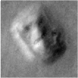 |
Fig. 2 Registered and enhanced pair of images of the Face from frames 35A72 (left) and 70A13 (right).
Fig. 3 Local constrast enhancement of subtle features on the right, shadowed side of the Face from 70A13.
Fig. 4 Enhancement of a polyhedral object within the City that resembles a Fortress.
Fig. 5 Isometric plot of the 3-D reconstruction obtained using the single image shape-fromshading algorithm on 70A13. A similar result was obtained for 35A72.
(Images regenerated from scan of the original article)
Fig. 6 Cross-check of single image shape from shading results: Original images of 35A72 (a) and 70A13 (b). Synthetic images of the 3-D surface estimated from 35A72 and viewed under lighting conditions of 35A72 (c) and 70A13 (d). Synthetic images of the 3-D surface estimated from 70A13 and viewed under lighting conditions of 35A72 (e) and 70A13 (f).
(Images regenerated from scan of the original article)
Fig. 7 Synthetic images of the Face as it might appear under different illumination conditions. Images (a) and (c) were obtained by illuminating the 3-D surfaces computed from 35A72 and 70A13 under simulated afternoon light. Images (b) and (d) are the corresponding views under simulated morning light.
Fig. 8 Perspective views of the Face generated by projecting the image of 35A72 onto its 3-D surface. The views were generated for simulated camera positions around the Face.