For as long as I’ve been writing shaders, there’s been one specific shader I’ve always tried to write. And I’ve always failed at it for reason I could never fully understand. I’d wait a few years and try again with my new level of knowledge, get closer, and fail again. That goal?
To make a grid shader that mimics, but looks better than, a texture based grid.
Note: I highly recommend viewing this article in dark mode. If on desktop, open images into a new tab so you can view them with a dark background.
Table of Contents
- The Competition
Con-text-ure (Texture Based Grid)
MyFirstGrid.shader (Common Grid Shaders)
Choo Choo! (Filtered Pulsetrain)
Hi IQ (Box Filtered Grid) - The Contender
Line One, Begin(ner Line Shader)
Phoning It In (Phone-wire AA)
Right At The Wrong Place
It’s A Moiré (Interference Pattern Suppression)
Flipping Out (Line Inversion)
One More Thing (Partial Derivative Length) - Conclusion
- Shader Code
- Additional Thoughts
Anti-Aliasing Wider than Line
Aliasing in RGSS Texture Grid
Kaiser Filter
More Complex Surfaces and UVs
The Competition
Con-text-ure (Texture Based Grid)

This is using Rotated Grid Super Sampling from my article on Sharper Mipmapping, along with 16x Anisotropic filtering. This is basically as good as a simple texture based grid can look while still being reasonably performant.
And it seems simple enough to write a grid shader. Making grid lines in a shader is one of those early things you see in shader tutorials. So why have I been obsessed with this for so long? Because it’s harder than it might look to get right, and I know a shader based solution could look even better. Really that’s it. I just wanted to understand the problem space better.
Lets look a little closer at the above texture based grid to see some of the problem areas that still show up.

As you can see some of the thin lines still end up aliasing, in the far mid range there’s some aliasing and Moiré patterns, and in the far distance the lines end up getting fatter and then cutting off early as the anisotropic filtering runs out of steam. They’re also only stay sharp close up if you have a large enough texture, otherwise they start to get a little blurry.

MyFirstGrid.shader (Common Grid Shaders)
So what about one of those tutorial grid shaders? Start with a repeating UV. Draw some lines using a smoothstep() and fwidth(). And we’re done!
Right? (Don’t worry, I’ll show the code later.)

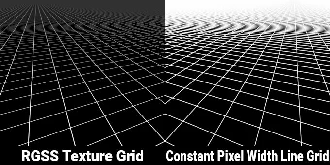
But there’s a catch. Most example grid shaders, like this one, use screen space width lines. That can be preferred over a texture based grid in a lot of use cases, and honestly probably what most people want. But it’s not what I’m trying to achieve. As the lines of that kind of grid go into the distance, eventually the each grid cell is less than a pixel wide, and thus the lines converge into a solid color that’s the same color as the lines.
That’s not what happens with a texture based grid. With a texture based grid, the lines themselves have perspective and get thinner the further away they are. Eventually fading out once below pixel wide.

They both converge solid color, but the texture based grid converges to a color that’s relative to the line coverage of the grid cell area.
Not to mention the obvious Moiré patterns once the grid gets smaller than a pixel across.
Most of the example shaders I’ve seen in the past that do try to do lines that are constant world space or UV space width don’t really handle this properly. They usually use a UV space faded edge or no line anti-aliasing at all, both of which end up aliasing horribly in the distance. Or they cheat and fade out the lines at some arbitrary distance to hide the artifacts. And the ones that don’t fade the lines out just end up looking similar to constant pixel width line grids in the distance. Only with worse aliasing and more pronounced Moiré patterns.

None of this matches what a texture based grid looks like. Though it does at least mostly match the perspective on the individual lines themselves.

Choo Choo! (Filtered Pulsetrain)
But there are some existing examples that look to solve it properly. One was pointed out to me recently, but has been around for far longer than I’ve been writing shaders. This technique was published in Apodaca, Anthony A., and Larry Gritz, eds. 1999. Advanced RenderMan: Creating CGI for Motion Pictures. And later in RenderMan’s documentation. The filtered pulsetrain.

This technique is intended to solve the exact issue I’ve been trying to. They analytically solved the integral for a convolved pulsetrain. Which, if you’re like me and didn’t finish their college level math courses, means absolutely nothing. I dropped out of art school, so it’s mostly over my head.
The short version is the function returns the ratio of line to not line within an arbitrary range. And it works incredibly well. Compared to the texture based grid it’s nearly a perfect match in terms of how it handles fading into the distance.

At least at first glance. Closer inspection shows some issues.

While it matches the perceptual brightness of a texture based grid, and there’s no aliasing in the foreground, the aliasing and Moiré in the mid to far distances are significantly worse. Essentially all visible line anti-aliasing disappears. It’s better than no anti-aliasing at all, and the Moiré patterns are less apparent than the pixel and UV width line grids. But this is still not as clean as I was expecting it to be.
Interestingly there’s this note in the book:

… the most egregious aliasing is gone.
The most egregious, but not all. I have to assume the original authors knew it didn’t remove all aliasing, but were happy enough with the results to not go further with it. And subsequent people using it also didn’t care, or just didn’t look close enough to notice?
Hi IQ (Box Filtered Grid)
There’s also the example from Inigo Quilez in his article on filterable procedurals, the box filtered grid.

The box filtered grid function does solve some issues with the filtered pulsetrain, mainly the fact it is highly sensitive to precision and thus starts showing noise artifacts not far away from the origin. But they otherwise behave roughly the same. That includes the same aliasing problems in the mid to far distance.

Though they are slightly different in the aliasing and Moiré patterns each show.

Now while I understand from a high level how both shaders work, I’m simply not smart enough at mathing to understand how to modify them to get what I wanted.
The Contender
Actually, what do I want from a grid shader? I want:
- User configurable line widths.
- Lines that have perspective thickness, not just a constant pixel width.
- No aliasing at all, at any distance or view orientation.
- A line width of 0.0 or 1.0 should show completely hidden or filled.
- Limited Moiré interference patterns.
- Blends to the same value in the distance that texture based grids do.
- Usable for real time rendering in place of alternative techniques.
So, I went back to the shaders I do know well, the pixel and UV width line grids. And then decided to start poking at those to see what I could change to make it work how I wanted. Or rather, start with a single line and build up from there.
Lets do a very quick overview of what makes for a basic grid shader with user configurable line widths.
First we need to draw a single line.
Line One, Begin(ner Line Shader)
The way I like to draw lines is using the smoothstep() function.
float lineUV = abs(uv.x * 2.0);
float line = smoothstep(lineWidth + lineAA, lineWidth - lineAA, lineUV);
The UV is used as a gradient. I then use an abs() on the UV so the gradient is positive on both sides of 0.0, and thus the smoothstep() is applied to both sides and we get a line instead of just an edge. Why do I multiply the UV by 2? This is so the lineWidth and lineAA can be specified in total width instead of half widths, or needing to divide them by 2.
For now lets use the world position as the UV, and some arbitrary values for lineWidth and lineAA. And that gets us this:

The problem with this is the anti-aliasing fails in the distance, and gets blurry in the foreground. Why? Because the width of the edge gradient needs to change depending on the angle and distance from the camera. To do that we can use one of my favorite tools, screen space partial derivatives. Something I’ve written about a few times in my previous articles. The short explanation is you can get how much a value changes between one pixel and the one next to it, either vertically or horizontally. And by getting the partial derivatives of the starting UV, we can know how wide the smoothstep() needs to be in UV space to appear 1 pixel wide.
float lineAA = fwidth(uv.x); //
float lineUV = abs(uv.x * 2.0);
float line = smoothstep(lineWidth + lineAA, lineWidth - lineAA, lineUV); //
And now the line’s edges are nice and sharp. Note, I’m getting the derivatives of the UV before doing any modifications to them. This keeps them in the “full width” scale, and also avoids some issues in the next step.
Lets make this a repeating line instead of just a single line.
float lineAA = fwidth(uv.x);
float lineUV = 1.0 - abs(frac(uv.x) * 2.0 - 1.0); //
float line = smoothstep(lineWidth + lineAA, lineWidth - lineAA, lineUV);
To explain that funky bit of code I’m doing to the UV, this is transforming a sawtooth wave into a triangle wave, and then making sure the zero points align with where they were before.
We’re starting with a lineUV like this:

Using frac(uv.x) instead gets you this:

Then the abs(frac(uv.x) * 2.0 - 1.0) gets you this:

But that has the “0.0" position starting at 1.0 instead of 0.0, so when we draw the lines they’ll be offset by half a period. So we add that 1.0 - at the start to get this:

And now when we draw the lines the “first” line’s position matches that single line we had before.
Now, lets make it into a full grid. To do that we just need to do these steps to both axis of the UV, and combine the results.
float2 lineAA = fwidth(uv);
float2 gridUV = 1.0 - abs(frac(uv) * 2.0 - 1.0);
float2 grid2 = smoothstep(lineWidth + lineAA, lineWidth - lineAA, gridUV);
float grid = lerp(grid2.x, 1.0, grid2.y); //
And that gets us a basic UV width line grid shader!
That lerp(grid2.x, 1.0, grid2.y) should probably get a little explaining. How to combine the two axis of repeating lines for a grid shader has something I was long confused about. I’d use max(x, y), or saturate(x + y), or a few other ways to combine them and they never quite felt right to me. It took me quite a while before I thought about it in terms of “how would I overlap two transparent things normally?” I’d use an alpha blend. In this case, that lerp() is equivalent to a premulitplied alpha blend, which you could also write like this:
float grid = grid2.x * (1.0 - grid2.y) + grid2.y;Alternatively, if you write the shader such that you have black lines on a white background, multiplying the axis together also produces the equivalent of a premultiplied blend. Note the + and - in the smoothstep() are swapped in the below example compared to the first one.
float2 lineAA = fwidth(uv);
float2 gridUV = 1.0 - abs(frac(uv) * 2.0 - 1.0);
float2 grid2 = smoothstep(lineWidth - lineAA, lineWidth + lineAA, gridUV); //
float grid = 1.0 - grid2.x * grid2.y; //
However I’ll be continuing to use the original code sample as they end up exactly the same in the end.
In retrospect using a premultiplied blend felt incredibly obvious, but it took over a decade for it to click for some reason. This is after I’ve written countless shaders that have done exactly this for other use cases. I even wrote an entire article on this exact topic.
Anyhoo, with that bit of code, we get this:

Looks pretty good, apart from the Moiré patterns. But we were expecting that. Now lets reduce the line widths down a bit to something closer to what one might actually use.

Uh oh. It looks good when the lines are close to the camera. But the lines start to alias pretty quickly. We saw these issues earlier in this article when I showed the constant UV width line grid before, but this looks slightly darker and more aliased than that original example. Why?

Well, because there’s one minor difference between the code used between the two. I use a 1.5 pixel wide AA when using smoothstep(). The reason for this is is because smoothstep() sharpens the edge gradient being used for anti-aliasing such that a 1.5 pixel wide smoothstep has a roughly similar slope to a 1 pixel wide linear gradient.

A 1 pixel wide smoothstep can then be too sharp. The reason for using a smoothstep at all is because when using a 1.5 pixel wide smoothstep adds just a small bit of extra anti-aliasing without affecting the perceived sharpness of the line vs a 1 pixel wide linear gradient.

To be fair, this is an increadibly small difference. But HLSL’ssmoothstep() is still nice because it additionally acts as an inverse lerp (aka remap) and clamping the value between 0.0 and 1.0. So it helps with simplifying the code. It also doesn’t entirely remove the perceived aliasing still, but we’ll come back to that.
In the end we have this shader code for our constant UV width grid:
float2 uvDeriv = fwidth(uv); //
float2 lineAA = uvDeriv * 1.5; //
float2 gridUV = 1.0 - abs(frac(uv) * 2.0 - 1.0);
float2 grid2 = smoothstep(lineWidth + lineAA, lineWidth - lineAA, gridUV);
float grid = lerp(grid2.x, 1.0, grid2.y);
What about a constant pixel width line grid? Well, that’s a trivial change. Multiply the line width by the derivatives! (Just remember,lineWidth is now the number of pixels wide the line is and not a value between 0.0 and 1.0.)
float2 uvDeriv = fwidth(uv);
float2 drawWidth = uvDeriv * lineWidth; //
float2 lineAA = uvDeriv * 1.5;
float2 gridUV = 1.0 - abs(frac(uv) * 2.0 - 1.0);
float2 grid2 = smoothstep(drawWidth + lineAA, drawWidth - lineAA, gridUV); //
float grid = lerp(grid2.x, 1.0, grid2.y)
Now we’re back to where we were earlier in the article. And have two shaders that fulfil at least two of my requirements. But we haven’t solved any of the problems we didn’t already know how to solve and one only has the perspective lines and the other solves most of the aliasing.
So lets focus on a single line for the moment instead of a whole grid. How can we make a single line have both the perspective thickness and no aliasing?
Phoning It In (Phone-wire AA)
One of my favorite tricks for anti-aliasing lines comes from Emil Persson. Specifically his Phone-wire AA example.
The basic idea behind this technique is don’t let something get thinner than one pixel. Instead clamp the size of the thing so it stays at least one pixel wide and then fade it out. This ends up looking much better than just letting a line get thinner than one pixel as if you do that it will always end up aliasing. The two bits of magic are how you keep things one pixel wide, and more importantly how much you fade them out by.
In Emil Persson’s example, he uses knowledge about how wide the wire geometry is, the distance from the camera each vertex is, and camera’s projection matrix to keep the wires one pixel thick. But for this shader, we can use those partial derivatives again! We just need to limit how thin line gets in screen space. Basically, we combine the two shaders we already have, and take the max of the UV line width and UV derivatives.
float uvDeriv = fwidth(uv.x);
float drawWidth = max(lineWidth, uvDeriv); //
float lineAA = uvDeriv * 1.5;
float lineUV = abs(uv.x * 2.0);
float line = smoothstep(drawWidth + lineAA, drawWidth - lineAA, lineUV);
That’s the first trick. But the second one is the big one. We fade out the line based on how thick we wanted them divided by how thick we’re drawing them.
float uvDeriv = fwidth(uv.x);
float drawWidth = max(lineWidth, uvDeriv);
float lineAA = uvDeriv * 1.5;
float lineUV = abs(uv.x * 2.0);
float line = smoothstep(drawWidth + lineAA, drawWidth - lineAA, lineUV);
line *= saturate(lineWidth / drawWidth); //
Looking good! You can actually see the perspective of that line even when it’s thin. And there’s no aliasing in the distance!

Of note, this also solves the issue of having the line not fully disappear when the intended line width is zero! It’ll gracefully fade the line out the thinner and thinner it gets, just like it does as it recedes into the distance, eventually fading out entirely when it gets to zero.
With that working, lets go back to a full grid again.
float2 uvDeriv = fwidth(uv);
float2 drawWidth = max(lineWidth, uvDeriv); //
float2 lineAA = uvDeriv * 1.5;
float2 gridUV = 1.0 - abs(frac(uv) * 2.0 - 1.0);
float2 grid2 = smoothstep(drawWidth + lineAA, drawWidth - lineAA, gridUV);
grid2 *= saturate(lineWidth / drawWidth); //
float grid = lerp(grid2.x, 1.0, grid2.y);
Much better! … sort of. That doesn’t look quite right. It’s fading to black at the horizon! As a reminder, the texture based grid fades to a grey, not black.

The problem is in a grid a single line can only get so wide before it’s wider than an entire grid cell width. When it’s a single line by itself, this isn’t an issue. But when it’s drawn as a grid, in the areas it’s going black a single pixel is wider than multiple overlapping grid widths. But we’re still only drawing a single set of lines in each pixel, not multiple grid cells worth.
Where I got stuck for a long time in writing these shaders is what to do next. And I focused far too long on trying to figure out how to properly calculate the value to fade the line by, but nothing really seemed to fix it properly. I’m sure this is solvable, but remember how I said I was an art school drop out? Yeah, I’m not the one who’s going to figure that out. I’m going down this path because I’m not mathy enough to do it the “right” way.
The closest I got going down that path was trying to clamp the value I was dividing the line width by to a max of 1.0. My theory being if the line can’t be wider than one pixel, don’t divide by more than 1. And while this is better, it’s still not correct.
grid2 *= saturate(lineWidth / max(1.0, drawWidth));
It’s very subtle, but this results in there being a bit of a dark “gutter” at the transition between the individually distinguishable lines and the mostly solid color at the horizon.

As shown before, the filtered pulsetrain and box filtered grid do solve this problem. Not by fading lines exactly, but by always calculating the total coverage of all possible lines within the current pixel’s coverage. But as I’ve shown, neither properly handle anti-aliasing of those lines! And again, art school drop out here. I don’t have the knowledge to do it the way they did.
So now what?
Right At The Wrong Place
After a few years of getting about this far and not really getting any further, I recently sat down and tried to think through it more. Why didn’t that code work? It feels like it should, so what was I missing?
Well, it turns out I was doing the right thing. I just in the wrong place in the code. If I limited the actual drawWidth, it works!
float2 uvDeriv = fwidth(uv);
float2 drawWidth = clamp(lineWidth, uvDeriv, 0.5); //
float2 lineAA = uvDeriv * 1.5;
float2 gridUV = 1.0 - abs(frac(uv) * 2.0 - 1.0);
float2 grid2 = smoothstep(drawWidth + lineAA, drawWidth - lineAA, gridUV);
grid2 *= saturate(lineWidth / drawWidth);
float grid = lerp(grid2.x, 1.0, grid2.y);
Yes, the Moiré is a bit more pronounced, but the overall brightness is finally correct!
A curious thing is I’m clamping the draw width to 0.5, not 1.0. If I use 1.0 it’s too dark on the horizon again.
float2 drawWidth = clamp(lineWidth, uvDeriv, 1.0);
If your thought is “well, maybe you just needed to use 0.5 in the previous attempt?” Nope, that’s too bright!
grid2 *= saturate(lineWidth / max(0.5, drawWidth));
Why is 0.5 the correct value to clamp the draw width? Well, it has to do with the way the line anti-aliasing works.
If we look at some width limited lines without any fading code. If the we manually override the uvDeriv used, we can see how the lines expand and smooth out as they would getting further from the camera.

When limited to a width of 0.5, like above, it means there’s an equal amount of area that’s above and below 0.5 (the red line). Meaning the average value across the whole vertical is 0.5 beyond a uvDeriv of 0.5.
This average of 0.5 means when we fade the line out, and also dividing by 0.5, that’s dividing by the same (average) intensity we know those pixels will be.
If limited to a width of 1.0, we get this instead.

Now anywhere past a uvDeriv of 1.0 is above an average of 0.5, with how much above depending on how large the uvDeriv is. But it’s also not an average of 1.0! This is important because the math fading it out assumes it is, resulting in it getting too dark, which is what we saw in the failed example 2.
If we don’t limit the line width, and only limit the value we divide by, the “0.5” point disappears entirely as it’s being cut off by the edge of the grid cell, meaning the average brightness is even more above 0.5, but also still not 1.0! And that means if we clamp only the value we divide by in the fade calculation to 0.5 it stays too bright, which is what we saw in the failed example 3.
This is probably the hardest aspect of this whole thing to explain, so I apologize if it’s still confusing.
It’s A Moiré (Interference Pattern Suppression)
However we’re still left with those more pronounced Moiré patterns. This is because we still don’t handle when the grid cells are smaller than a single pixel. It correctly averages to the appropriate value, but that’s not really the only issue. And this is where I decided to cheat a little. Remember how one of my main goals is to limit Moiré patterns as much as possible? Well, this is one place where I want to diverge heavily from how a texture based grid, or even ground truth, would look. Those will always have some Moiré artifacts because that’s really what happens when viewing a fine grid.
So instead of figuring out how to do all the math to calculate it the correctly, why not fade to a solid color? Yes, I know it was one of the things I lambasted about a lot of other implementations, but I’m not going to fade just based on some arbitrary distance. I’m going to fade out based on when I know those Moiré patterns are going to appear. And how do you do that? Easy! Using the same UV derivatives we’re already using for anti-aliasing!
float2 uvDeriv = fwidth(uv);
float2 drawWidth = clamp(lineWidth, uvDeriv, 0.5);
float2 lineAA = uvDeriv * 1.5;
float2 gridUV = 1.0 - abs(frac(uv) * 2.0 - 1.0);
float2 grid2 = smoothstep(drawWidth + lineAA, drawWidth - lineAA, gridUV);
grid2 *= saturate(lineWidth / drawWidth);
grid2 = lerp(grid2, lineWidth, saturate(uvDeriv * 2.0 - 1.0)); //
float grid = lerp(grid2.x, 1.0, grid2.y);
The idea here is once the derivatives are greater than 1.0, the grid cells are smaller than a pixel, which is when the Moiré patterns start to appear more noticeably. So this starts to fade to a solid color when the derivatives are 0.5, which is when the anti-aliased lines start to merge. And finishes fading when the derivatives are 1.0.
And that’s it! All six of the items on my list for a “perfect” grid shader are satisfied! So we’re done, right?
Flipping Out (Line Inversion)
Well, sort of. What happens when you try to make the grid lines wider than 0.5? Nothing, because we clamped the line width to 0.5. This is obviously for a very niche use case, but technically I’ve only succeeded in half of the requirement of “0.0 or 1.0 should show completely hidden or filled”. A line width of 0.0 will hide that axis entirely, but a 1.0 will cap out at a width of 0.5. But if we let lines get wider than that, things go wonky with the above math.
The final trick is we never actually draw lines more than half a grid width wide. Instead if the line width is over 0.5, we flip a few things around and effectively draw black lines on white offset by half a grid width. This means most of the math doesn’t have to change.
float2 uvDeriv = fwidth(uv);
bool2 invertLine = lineWidth > 0.5; //
float2 targetWidth = invertLine ? 1.0 - lineWidth : lineWidth; //
float2 drawWidth = clamp(targetWidth, uvDeriv, 0.5); //
float2 lineAA = uvDeriv * 1.5;
float2 gridUV = abs(frac(uv) * 2.0 - 1.0);
gridUV = invertLine ? gridUV : 1.0 - gridUV; //
float2 grid2 = smoothstep(drawWidth + lineAA, drawWidth - lineAA, gridUV);
grid2 *= saturate(targetWidth / drawWidth);
grid2 = lerp(grid2, targetWidth, saturate(uvDeriv * 2.0 - 1.0));
grid2 = invertLine ? 1.0 - grid2 : grid2; //
float grid = lerp(grid2.x, 1.0, grid2.y);
One More Thing (Partial Derivative Length)
There’s one last very small tweak to this shader that I make use of. That is that I don’t use fwidth(). The fwidth() function is an approximation for getting the length of the derivatives. That function looks something like this:
float fwidth(float a)
{
  return abs(ddx(a)) + abs(ddy(a));
}
That’s not how you calculate the length of something. It’s accurate enough when things align to the screen axis, but on diagonals they’re always going to be too wide. The correct way to calculate the length of the derivatives is like this:
float ddLength(float a)
{
  return length(float2(ddx(a), ddy(a)));
}
Or is it? Inigo Quilez’s article on checkerboard filtering contends the correct way to do it is to get the absolute max of the derivatives.
float ddMax(float a)
{
  return max(abs(ddx(a), abs(ddy(a)));
}
Well, lets compare them and see which one looks better. This is going to require zooming in real close because the differences are minimal.

And here I would say the length() option is the correct one. It strikes the right balance of sharpness without aliasing compared to the other two. It should be noted that fwidth() was never meant to be correct, just a fast approximation. And it is faster, but for modern GPUs the difference is negligible. And the max() method isn’t “wrong” either, just wrong for this use case. The way Inigo Quilez’s filtered procedurals work is different than this shader, so it’s likely correct for that use case. Though his Shader Toy examples all use a slightly different calculation with an arbitrary fudge factor added, so maybe it’s not correct for that use case either?
Ultimately, it’s mostly subjective as to which looks best, and the max() method is just as cheap as fwidth() while being a potentially slightly better approximation. And it’s always good to check your assumptions on things like this by actually trying them out and doing direct comparisons.
But, with that last tweak, the code looks like this:
float4 uvDDXY = float4(ddx(uv), ddy(uv)); //
float2 uvDeriv = float2(length(uvDDXY.xz), length(uvDDXY.yw)); //
bool2 invertLine = lineWidth > 0.5;
float2 targetWidth = invertLine ? 1.0 - lineWidth : lineWidth;
float2 drawWidth = clamp(targetWidth, uvDeriv, 0.5);
float2 lineAA = uvDeriv * 1.5;
float2 gridUV = abs(frac(uv) * 2.0 - 1.0);
gridUV = invertLine ? gridUV : 1.0 - gridUV;
float2 grid2 = smoothstep(drawWidth + lineAA, drawWidth - lineAA, gridUV);
grid2 *= saturate(targetWidth / drawWidth);
grid2 = lerp(grid2, targetWidth, saturate(uvDeriv * 2.0 - 1.0));
grid2 = invertLine ? 1.0 - grid2 : grid2;
float grid = lerp(grid2.x, 1.0, grid2.y);
And lets compare this to to the other best looking options, the texture based grid and box filtered grid.

Conclusion
I hope you’ll agree that we finally have the smoothest, most alias free, least Moiré patterned, most pristine gird shader you could possibly have. And one that in my eyes visually beats both texture based grids, and the previously best in class options.

At least until Mr. Quilez writes a shader that beats this one.
Shader Code
Here is an example GLSL implementation in ShaderToy, especially if you want an example of it in motion.
Here is an example Unreal material function graph.
(direct link to blueprintUE)

And here is an example Unity shader.
(direct link to gist)
Additional Thoughts
Anti-Aliasing Wider than Line
For the three of you who noticed, yes, the anti-aliasing pixel width is wider than the minimum line pixel width. And that does indeed reduce the maximum brightness of the lines in some cases, slightly. But not in any perceivable way. And the wider anti-aliasing makes up for any perceived brightness loss. It is really only measurable in the rare places a pixel falls right in center of a line, which is not most of the time.

Do these smoothstep() lines look darker to you?
Aliasing in RGSS Texture Grid
Some have notice the texture based grid examples in this article are a little more aliased than they would expect. This is in part a failing of the RGSS shader itself. Because it uses a rotated grid to do the super sampling it has some issues if edges line up with those samples. 4x MSAA has this same issue, and the RGSS shader uses the same sample pattern. Perspective grids like this are one of the hardest things for the RGSS and 4x MSAA handle because there’s guaranteed to be a few grid lines that are affected.
Because of this issue with the 4x MSAA pattern, anti-aliased grids are also very hard when using geometry or hardware line based grids as 4x MSAA is the most commonly used.
However it’s also an artifact of using anisotropic filtering itself, which is approximated on GPUs. How exactly it’s approximated is different between each vendor and even between generations. And the exact methods used seem to be fairly closely guarded secrets between each company. But generally they tend to do as few extra texture samples as possible at a handful of mip bias levels. Search for EWA or FELINE if you’re interested in reading up more on that. But in short, even without RGSS some aliasing appears.

The major difference between these two examples is in how far into the horizon the lines stay sharp, and there’s a little less fuzziness on some of the vertical lines.
Because the implementation of anisotropic filtering is GPU dependent, how much aliasing appears when using it will also be. For example, it looks and looks slightly different between an Nvidia GTX 970, RTX 2080 Super, and RTX 3080.
Kaiser Filter
If you’ve read my Sharper Mipmapping article, you may be wondering how Kaiser filtering looks for this grid. Is it better than the default box filter? Better than this new shader even!?
No. Mostly looks exactly the same as box filtered, but a little too bright as the mipmaps no longer have the same average intensity as previous mipmaps. Kaiser filtering helps with minification when viewed mostly straight on, but it’s less effective when viewed at more glancing angles. Thin black and white lines are also the worst case scenario for Kaiser filtering.
And no, I’m not going to give you an example to compare against. ;)
More Complex Surfaces and UVs
One of the nice things about the way this shader works is that it isn’t limited to just a flat plane and regular grid. It generalizes to far more complex geometry with no modifications. And to different UV layouts with only minor modifications, mainly to handle line width and derivative discontinuities.
Here’s what the shader looks like on a lumpy terrain.

And here’s a modified shader using the same techniques, but using a radial UV, along with one of derivative discontinuity fixes I’ve detailed elsewhere.

And another version that supports triplanar mapping.
(Unreal Engine material function version here.)

And because it’s the most commonly asked about feature, here’s a shader that has separate major grid divisions and axis lines.