.NET nanoFramework Qorvo DW1000 – Makerfabs Device SPI

The Makerfabs ESP32 UWB(Ultra Wideband) module has a Qorvo DW1000 and Espressif ESP32 module. The Espressif ESP32 module can run the .NET nanoFramework but does not have a Qorvo DW1000 library. (March2023)

Makerfabs ESP32 UWB(Ultra Wide Band) module

Before any coding I used nanoff to “flash” the Espressif ESP32 module with the latest version of .NET nanoFramework

Flashing Makerfabs ESP32 UWB module with nanoff

The Qorvo DW1000 module has a Serial Peripheral Interface (SPI) so the Master In Slave Out(MISO), Master Out Slave In(MOSI), Serial Clock(SCLK) and Chip Slave Select(CSS) pins have to be configured using the Configuration.SetPinFunction method of the nanoFramework.Hadware.Esp32 library

Makerfabs ESP32 UWB module schematic

Even though SPI is an industry standard there are often subtle differences which need to be taken into account when reading from/writing to registers. The DW1000 has a static “Device Identifier” which I used to debug my “proof of concept” code.

DW1000 Datasheet Register Map documentation for Register 0x00

The DeviceSPI program reads register 0x00 and then displays the decoded payload.

public class Program
{
#if MAKERFABS_ESP32UWB
    private const int SpiBusId = 1;
    private const int chipSelectLine = Gpio.IO04;
#endif

    public static void Main()
    {
        Thread.Sleep(5000);

        Debug.WriteLine("devMobile.IoT.Dw1000.ShieldSPI starting");

        try
        {
#if MAKERFABS_ESP32UWB
            Configuration.SetPinFunction(Gpio.IO19, DeviceFunction.SPI1_MISO);
            Configuration.SetPinFunction(Gpio.IO23, DeviceFunction.SPI1_MOSI);
            Configuration.SetPinFunction(Gpio.IO18, DeviceFunction.SPI1_CLOCK);
#endif
            var settings = new SpiConnectionSettings(SpiBusId, chipSelectLine)
            {
                ClockFrequency = 2000000,
                Mode = SpiMode.Mode0,
            };

            using (SpiDevice device = SpiDevice.Create(settings))
            {
                Thread.Sleep(500);

                while (true)
                {
                    /*
                    byte[] writeBuffer = new byte[] { 0x0, 0x0, 0x0, 0x0, 0x0 }; // 0x0 = DEV_ID
                    byte[] readBuffer = new byte[writeBuffer.Length];

                    device.TransferFullDuplex(writeBuffer, readBuffer); // 15, 48, 1, 202, 222
                    */

                    byte[] writeBuffer = new byte[] { 0x0 }; // 0x0 = DEV_ID
                    byte[] readBuffer = new byte[5];

                    device.TransferFullDuplex(writeBuffer, readBuffer); // 15, 48, 1, 202, 222
                       
                    uint ridTag = (uint)(readBuffer[4]<< 8 | readBuffer[3]);
                    byte model = readBuffer[2];
                    byte ver = (byte)(readBuffer[1] >> 4);
                    byte rev = (byte)(readBuffer[1] & 0x0f);

                    Debug.WriteLine(String.Format($"RIDTAG 0x{ridTag:X2} MODEL 0x{model:X2} VER 0X{ver:X2} REV 0x{rev:X2}"));

                    Thread.Sleep(10000);
                }
            }
        }
        catch (Exception ex)
        {
            Debug.WriteLine(ex.Message);
        }
    }
}
Visual Studio 2022 Debug window displaying the decoded value from Register 0x0

The DW1000 User Manual is > 240 pages, with roughly 140 pages of detailed documentation about the DW1000 register set so progress will be slow.

.NET nanoFramework Qorvo DW1000 – flashing & flashing

A few months ago one of my customers purchased five Makerfabs ESP32 UWB(Ultra Wideband) devices to see how the range of Qorvo DW1000 modules was impacted by the steel gates and fences in a stock yard. The .NET nanoFramework runs on Espressif ESP32 devices but there is currently (Feb2023) no Qorvo DW1000 module support so I borrowed the devices.

First step was to use nanoff to flash the device with the latest suitable firmware

The Makerfabs board has 5 LEDs, one illuminated when the device has power, and the other four are connected to the Qorvo DW1000 module.

Makerfabs ESP32 UWB schematic

An important milestone for any hardware project is to get a Light Emitting Diode(LED) to flash but there none connected to the Espressif ESP32 module.

I used a Grove-4 pin Male Jumper to Grove 4 pin Conversion Cable to connect a Seeedstudio LED to the device

public class Program
{
    private static GpioController _gpioController;

    public static void Main()
    {
        _gpioController = new GpioController();

        //GpioPin led = _gpioController.OpenPin(Gpio.IO00, PinMode.Output);
        //GpioPin led = _gpioController.OpenPin(Gpio.IO01, PinMode.Output);
        //GpioPin led = _gpioController.OpenPin(Gpio.IO02, PinMode.Output);
        //GpioPin led = _gpioController.OpenPin(Gpio.IO03, PinMode.Output);
        GpioPin led = _gpioController.OpenPin(Gpio.IO04, PinMode.Output);

        led.Write(PinValue.Low);

        while (true)
        {
           led.Toggle();
           Thread.Sleep(125);
            led.Toggle();
            Thread.Sleep(125);
            led.Toggle();
            Thread.Sleep(125);
            led.Toggle();
            Thread.Sleep(525);
        }
    }
}

The test code was “inspired” by the .NET nanoFramework Blinky sample

Maduino LoRa Air Temperature and Soil Moisture

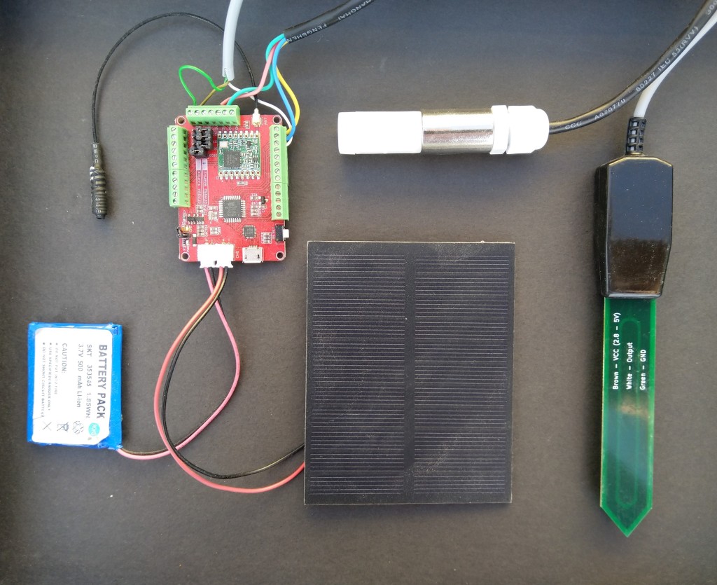
This is a demo MakerFabs Maduino LoRa Radio 868MHz client (based on Maduino LoRa 868MHz example) that uploads telemetry data to my Windows 10 IoT Core on Raspberry PI AdaFruit.IO and Azure IoT Hub field gateways.

The code is available on github

Sample hardware
Azure IoT Central data visualisation

The Maduino device in the picture is a custom version with an onboard Microchip ATSHA204 crypto and authentication chip (currently only use for the unique 72 bit serial number) and a voltage divider connected to the analog pin A6 to monitor the battery voltage.

There are compile time options ATSHA204 & BATTERY_VOLTAGE_MONITOR which can be used to selectively enable this functionality.

I use the Arduino lowpower library to aggressively sleep the device between measurements

// Adjust the delay so period is close to desired sec as possible, first do 8sec chunks. 
  int delayCounter = SensorUploadDelay / 8 ;
  for( int i = 0 ; i < delayCounter ; i++ )
  {
     LowPower.powerDown(SLEEP_8S, ADC_OFF, BOD_OFF);  
  }
  
  // Then to 4 sec chunk
  delayCounter =  ( SensorUploadDelay % 8 ) / 4;
  for( int i = 0 ; i < delayCounter ; i++ )
  {
     LowPower.powerDown(SLEEP_4S, ADC_OFF, BOD_OFF);  
  }

  // Then to 2 sec chunk
  delayCounter =  ( SensorUploadDelay % 4 ) / 2 ;
  for( int i = 0 ; i < delayCounter ; i++ )
  {
     LowPower.powerDown(SLEEP_2S, ADC_OFF, BOD_OFF);  
  }

  // Then to 1 sec chunk
  delayCounter =  ( SensorUploadDelay % 2 ) ;
  for( int i = 0 ; i < delayCounter ; i++ )
  {
     LowPower.powerDown(SLEEP_1S, ADC_OFF, BOD_OFF);  
  }
}

I use a spare digital PIN for powering the soil moisture probe so it can be powered down when not in use. I have included a short delay after powering up the device to allow the reading to settle.

  // Turn on soil mosture sensor, take reading then turn off to save power
  digitalWrite(SoilMoistureSensorEnablePin, HIGH);
  delay(SoilMoistureSensorEnableDelay);
  int soilMoistureADCValue = analogRead(SoilMoistureSensorPin);
  digitalWrite(SoilMoistureSensorEnablePin, LOW);
  int soilMoisture = map(soilMoistureADCValue,SoilMoistureSensorMinimum,SoilMoistureSensorMaximum, SoilMoistureValueMinimum, SoilMoistureValueMaximum); 
  PayloadAdd( "s", soilMoisture, false);

Bill of materials (Prices Nov 2019)

  • Maduino LoRa Radion (868MHz) 18.90
  • SHT20 I2C Temperature & Humidity Sensor (Waterproof Probe) USD22.50
  • Pinotech SoilWatch 10 – Soil moisture sensor USD23
  • Elecrow 1 Watt solar panel with wires USD3.80
  • 500 mAh LI-Ion battery

The software could easily be modified to support additional sensors.

Maduino LoRa Radio 868MHz Payload Addressing client

This is a demo MakerFabs Maduino LoRa Radio 868MHz client (based on one of the examples from Arduino-LoRa) that uploads telemetry data to my Windows 10 IoT Core on Raspberry PI AdaFruit.IO and Azure IoT Hub field gateways.

The code is available on Github

MaduinoLoRa86820180914
/*
Adapted from LoRa Duplex communication with Sync Word Sends temperature & humidity data from Seeedstudio https://www.seeedstudio.com/Grove-Temperature-Humidity-Sensor-High-Accuracy-Min-p-1921.html To my Windows 10 IoT Core RFM 9X library https://blog.devmobile.co.nz/2018/09/03/rfm9x-iotcore-payload-addressing/*/#include // include libraries#include#includeconst int csPin = 10; // LoRa radio chip selectconst int resetPin = 9; // LoRa radio resetconst int irqPin = 2; // change for your board; must be a hardware interrupt pin// Field gateway configurationconst char FieldGatewayAddress[] = "LoRaIoT1";const float FieldGatewayFrequency = 915000000.0;//const float FieldGatewayFrequency = 433000000.0;const byte FieldGatewaySyncWord = 0x12 ;// Payload configurationconst int PayloadSizeMaximum = 64 ;byte payload[PayloadSizeMaximum] = "";const byte SensorReadingSeperator = ',' ;// Manual serial number configurationconst char DeviceId[] = {"Maduino1"};const int LoopSleepDelaySeconds = 10 ;void setup() { Serial.begin(9600); while (!Serial); Serial.println("LoRa Setup"); // override the default CS, reset, and IRQ pins (optional) LoRa.setPins(csPin, resetPin, irqPin);// set CS, reset, IRQ pin if (!LoRa.begin(FieldGatewayFrequency)) { Serial.println("LoRa init failed. Check your connections."); while (true); } // Need to do this so field gateways pays attention to messsages from this device LoRa.enableCrc(); LoRa.setSyncWord(FieldGatewaySyncWord); //LoRa.dumpRegisters(Serial); Serial.println("LoRa Setup done."); // Configure the Seeedstudio TH02 temperature &amp;amp;amp;amp;amp;amp;amp;amp;amp; humidity sensor Serial.println("TH02 setup"); TH02.begin(); delay(100); Serial.println("TH02 Setup done"); Serial.println("Setup done");}void loop(){ int payloadLength = 0 ; float temperature ; float humidity ; Serial.println("Loop called"); memset(payload, 0, sizeof(payload)); // prepare the payload header with "To" Address length (top nibble) and "From" address length (bottom nibble) &lt;&lt; 4) | strlen( DeviceId ) ; payloadLength += 1; // Copy the "To" address into payload memcpy(&amp;amp;amp;amp;amp;amp;amp;amp;amp;payload[payloadLength], FieldGatewayAddress, strlen(FieldGatewayAddress)); payloadLength += strlen(FieldGatewayAddress) ; // Copy the "From" into payload memcpy(&amp;amp;amp;amp;amp;amp;amp;amp;amp;payload[payloadLength], DeviceId, strlen(DeviceId)); payloadLength += strlen(DeviceId) ; // Read the temperature and humidity values then display nicely temperature = TH02.ReadTemperature(); humidity = TH02.ReadHumidity(); Serial.print("T:"); Serial.print( temperature, 1 ) ; Serial.print( "C" ) ; Serial.print(" H:"); Serial.print( humidity, 0 ) ; Serial.println( "%" ) ; // Copy the temperature into the payload payload[ payloadLength] = 't'; payloadLength += 1 ; payload[ payloadLength] = ' '; payloadLength += 1 ; payloadLength += strlen( dtostrf(temperature, -1, 1, (char*)&amp;payload[payloadLength])); payload[ payloadLength] = SensorReadingSeperator; payloadLength += sizeof(SensorReadingSeperator) ; // Copy the humidity into the payload payload[ payloadLength] = 'h'; payloadLength += 1 ; payload[ payloadLength] = ' '; payloadLength += 1 ; payloadLength += strlen( dtostrf(humidity, -1, 0, (char *)&amp;[payloadLength])); // display info about payload then send it (No ACK) with LoRa unlike nRF24L01 Serial.print( "RFM9X/SX127X Payload length:"); Serial.print( payloadLength ); Serial.println( " bytes" ); LoRa.beginPacket(); LoRa.write( payload, payloadLength ); LoRa.endPacket(); Serial.println("Loop done"); delay(LoopSleepDelaySeconds * 1000l);}

In the debugging output the data looked like this

13:40:28-RX From Maduino1 PacketSnr 9.8 Packet RSSI -65dBm RSSI -110dBm = 11 byte message "t 33.7,h 51"
 Sensor Maduino1t Value 33.7
 Sensor Maduino1h Value 51
 AzureIoTHubClient SendEventAsync start
 AzureIoTHubClient SendEventAsync finish
The thread 0x268 has exited with code 0 (0x0).
The thread 0xb28 has exited with code 0 (0x0).
13:40:38-RX From Maduino1 PacketSnr 9.5 Packet RSSI -66dBm RSSI -112dBm = 11 byte message "t 33.9,h 51"
 Sensor Maduino1t Value 33.9
 Sensor Maduino1h Value 51
 AzureIoTHubClient SendEventAsync start
 AzureIoTHubClient SendEventAsync finish
13:40:49-RX From Maduino1 PacketSnr 9.5 Packet RSSI -66dBm RSSI -110dBm = 11 byte message "t 34.0,h 51"
 Sensor Maduino1t Value 34.0
 Sensor Maduino1h Value 51
 AzureIoTHubClient SendEventAsync start
 AzureIoTHubClient SendEventAsync finish


Bill of materials (Prices Sep 2018)


  • Maduino LoRa Radion (868MHz) USD14.10
  • Seeedstudio Temperature&Humidity Sensor USD11.50
  • 4 pin Female Jumper to Grove 4 pin Conversion Cable USD2.90
  • 1 Watt solar panel with wires USD3.80
  • 3000 mAh LI-Ion battery

There is also a 433MHz version available at the same price


The code is pretty basic, it shows how to pack the payload and set the necessary RFM9X/SX127X LoRa module configuration, has no power conservation, advanced wireless configuration etc.


The onboard sockets for battery and charging make the device easier to package and power in the field.


The Grove 4 pin Female Jumper to Grove 4 pin Conversion Cable was a quick & convenient way to get the I2C Grove temperature and humidity sensor connected up.


Then in my Azure IoT Hub monitoring software


MaduinoLoRaAzureIoT20180914
			

Azure IoT Hubs LoRa Windows 10 IoT Core Field Gateway

This project is now live on github.com, sample Arduino with Dragino LoRa Shield for Arduino, MakerFabs Maduino, Dragino LoRa Mini Dev, M2M Low power Node and Netduino with Elecrow LoRa RFM95 Shield clients uploaded in the next couple of days.

AzureIOTHubExplorerScreenGrab20180912

The bare minimum configuration is

{
  "AzureIoTHubDeviceConnectionString": "HostName=qwertyuiop.azure-devices.net;DeviceId=LoRaGateway;SharedAccessKey=1234567890qwertyuiop987654321qwertyuiop1234g=",
  "AzureIoTHubTransportType": "Amqp",
  "SensorIDIsDeviceIDSensorID": true,
  "Address": "LoRaIoT1",
  "Frequency": 915000000.0
}

So far battery life and wireless communications range for the Arduino clients is looking pretty good. CRC presence checking and validation is turned so have a look at one of the sample clients.

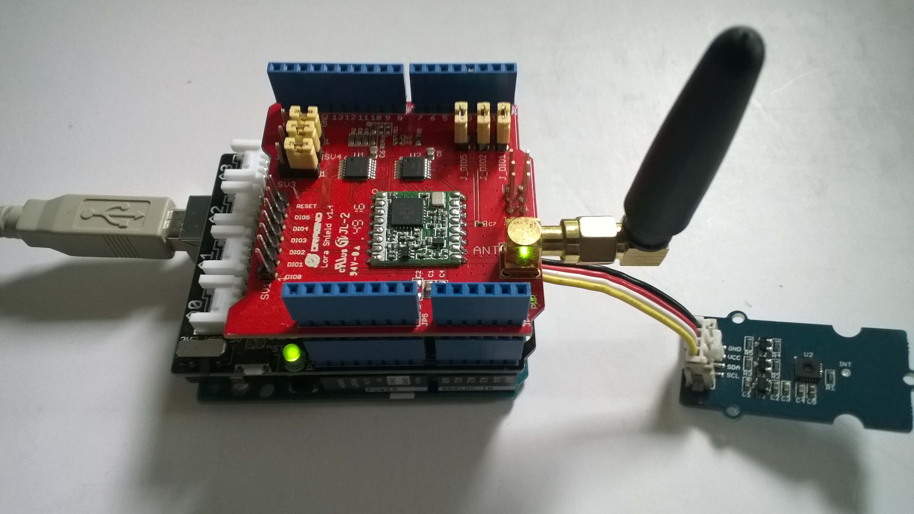
ArduinoUnoR3DraginoLoRa
It took a bit longer than expected as upgrading to the latest version (v1.18.0 as at 12 Sep 2018) of Microsoft.Azure.Devices.Client (from 1.6.3) broke my field gateway with timeouts and exceptions.

I’ll be doing some more testing over the next couple of weeks so it is a work in progress.

AdaFruit.IO LoRa Windows 10 IoT Core Field Gateway

This project is now live on github.com, sample Arduino with Dragino LoRa Shield for Arduino, MakerFabs Maduino, Dragino LoRa Mini Dev, M2M Low power Node and Netduino with Elecrow LoRa RFM95 Shield clients uploaded in the next couple of days.

AdaFruit.IO.LoRaScreenShot
While building this AdaFruit.IO LoRa field gateway, and sample clients I revisited my RFM9XLoRa-Net library a couple of times adding functionality and renaming constants to make it more consistent. I made many of the default values public so they could be used in the field gateway config file.
The bare minimum configuration is

{
“AdaFruitIOUserName”: “——“,
“AdaFruitIOApiKey”: “——“,
“AdaFruitIOGroupName”: “——”
“Address”: “——“,
“Frequency”: 915000000.0
}

So far battery life and wireless communications range for the Arduino clients is looking pretty good.

ArduinoUnoR3DraginoLoRa

Re-reading the SX1276 datasheet

I sat down and read the Semtech SX1276 datasheet paying close attention to any references to CRCs and headers. Then to test some ideas I modified my Receive Basic test harness to see if I could reliably reproduce the problem with my stress test harness.LoRaStress2

public sealed class StartupTask : IBackgroundTask
	{
		private const int ChipSelectLine = 25;
		private const int ResetLine = 17;
		private Rfm9XDevice rfm9XDevice = new Rfm9XDevice(ChipSelectLine, ResetLine);

		public void Run(IBackgroundTaskInstance taskInstance)
		{
			// Put device into LoRa + Sleep mode
			rfm9XDevice.RegisterWriteByte(0x01, 0b10000000); // RegOpMode 

			// Set the frequency to 915MHz
			byte[] frequencyWriteBytes = { 0xE4, 0xC0, 0x00 }; // RegFrMsb, RegFrMid, RegFrLsb
			rfm9XDevice.RegisterWrite(0x06, frequencyWriteBytes);

			rfm9XDevice.RegisterWriteByte(0x0F, 0x0); // RegFifoRxBaseAddress 

			rfm9XDevice.RegisterWriteByte(0x01, 0b10000101); // RegOpMode set LoRa & RxContinuous

			while (true)
			{
				// Wait until a packet is received, no timeouts in PoC
				Debug.WriteLine("Receive-Wait");
				byte IrqFlags = rfm9XDevice.RegisterReadByte(0x12); // RegIrqFlags
				while ((IrqFlags & 0b01000000) == 0)  // wait until RxDone cleared
				{
					Task.Delay(20).Wait();
					IrqFlags = rfm9XDevice.RegisterReadByte(0x12); // RegIrqFlags
					Debug.Write(".");
				}
				Debug.WriteLine("");

				if ((IrqFlags & 0b00100000) == 0b00100000)
				{
					Debug.WriteLine("Payload CRC error");
				}

				byte regHopChannel = rfm9XDevice.RegisterReadByte(0x1C);
				Debug.WriteLine(string.Format("regHopChannel {0}", Convert.ToString((byte)regHopChannel, 2).PadLeft(8, '0')));

				byte currentFifoAddress = rfm9XDevice.RegisterReadByte(0x10); // RegFifiRxCurrent
				rfm9XDevice.RegisterWriteByte(0x0d, currentFifoAddress); // RegFifoAddrPtr*
				byte numberOfBytes = rfm9XDevice.RegisterReadByte(0x13); // RegRxNbBytes

				// Allocate buffer for message
				byte[] messageBytes = new byte[numberOfBytes];

				for (int i = 0; i < numberOfBytes; i++)
				{
					messageBytes[i] = rfm9XDevice.RegisterReadByte(0x00); // RegFifo
				}
				rfm9XDevice.RegisterWriteByte(0x12, 0xff); // RegIrqFlags clear all the bits

				string messageText = UTF8Encoding.UTF8.GetString(messageBytes);
				Debug.WriteLine("Received {0} byte message {1}", messageBytes.Length, messageText);
				Debug.WriteLine(string.Format("RegIrqFlags {0}", Convert.ToString((byte)IrqFlags, 2).PadLeft(8, '0')));
				Debug.WriteLine("Receive-Done");
			}
		}
	}

The RegHopChannel register has a flag indicating whether there was a CRC extracted from the packet header.

regHopChannel 00000000
Received 23 byte message 1 Hello Arduino LoRa! 1
RegIrqFlags 01010000
Receive-Done
Receive-Wait
…………………………..
regHopChannel 00000000
Received 23 byte message 1 Hello Arduino LoRa! 2
RegIrqFlags 01010000
Receive-Done
Receive-Wait
……………………………
regHopChannel 00000000
Received 23 byte message 1 Hello Arduino LoRa! 3
RegIrqFlags 01010000
Receive-Done
Receive-Wait

I then modified my Arduino-LoRa library based client to include a CRC

void setup() {
  Serial.begin(9600);                   // initialize serial
  while (!Serial);

  Serial.println("LoRa Duplex - Set sync word");

  // override the default CS, reset, and IRQ pins (optional)
  LoRa.setPins(csPin, resetPin, irqPin);// set CS, reset, IRQ pin

  if (!LoRa.begin(915E6)) {             // initialize ratio at 915 MHz
    Serial.println("LoRa init failed. Check your connections.");
    while (true);                       // if failed, do nothing
  }

  LoRa.enableCrc();  // BHL This was my change

  LoRa.setSyncWord(0x12);           // ranges from 0-0xFF, default 0x34, see API docs

  LoRa.dumpRegisters(Serial);
  Serial.println("LoRa init succeeded.");
}

void loop() {
  if (millis() - lastSendTime > interval) {
    String message = "5 Hello Arduino LoRa! ";   // send a message
    message += msgCount;
    sendMessage(message);
    Serial.println("Sending " + message);
    lastSendTime = millis();            // timestamp the message
    //interval = random(2000) + 1000;    // 2-3 seconds
    interval = 1000;
  }

  // parse for a packet, and call onReceive with the result:
  onReceive(LoRa.parsePacket());
}

void sendMessage(String outgoing) {
  LoRa.beginPacket();                   // start packet
  LoRa.print(outgoing);                 // add payload
  LoRa.endPacket();                     // finish packet and send it
  msgCount++;                           // increment message ID
}

void onReceive(int packetSize) {
  if (packetSize == 0) return;          // if there's no packet, return

  // read packet header bytes:
  String incoming = "";

  while (LoRa.available()) {
    incoming += (char)LoRa.read();
  }

  Serial.println("Message: " + incoming);
  Serial.println("RSSI: " + String(LoRa.packetRssi()));
  Serial.println("Snr: " + String(LoRa.packetSnr()));
  Serial.println();
}

When I powered up a single client and the payload had a CRC

...............................
regHopChannel 01000000
Received 23 byte message 6 Hello Arduino LoRa! 6
RegIrqFlags 01010000
Receive-Done
Receive-Wait
.................................
regHopChannel 01000000
Received 23 byte message 6 Hello Arduino LoRa! 7
RegIrqFlags 01010000
Receive-Done
Receive-Wait
.................................
regHopChannel 01000000
Received 23 byte message 6 Hello Arduino LoRa! 8
RegIrqFlags 01010000
Receive-Done
Receive-Wait
...............................

Then when I increased the number of clients I started getting corrupted messages with CRC errors.

Received 24 byte message 6 Hello Arduino LoRa! 32
RegIrqFlags 01010000
Receive-Done
Receive-Wait
...............
regHopChannel 01000001
Received 25 byte message 8 Hello Arduino LoRa! 114
RegIrqFlags 01010000
Receive-Done
Receive-Wait
Payload CRC error
regHopChannel 01000000
Received 24 byte message s��=��(��p�^j�\ʏ�����
RegIrqFlags 01100000
Receive-Done
Receive-Wait
.............
regHopChannel 01000000
Received 24 byte message 6 Hello Arduino LoRa! 33
RegIrqFlags 01010000
Receive-Done
Receive-Wait
...............
regHopChannel 01000001
Received 25 byte message 8 Hello Arduino LoRa! 115
RegIrqFlags 01010000
Receive-Done
Receive-Wait

I need to do some more testing but now I think the problem was the RegIrqFlags PayloadCRCError flag was never going to get set because there was no CRC on the payload.