An Introduction to Radio Direction Finding
Radio direction finding (RDF) is more-or-less what it says on the tin - if someone is using a radio, how do you find out what direction they're in from where you are right now?
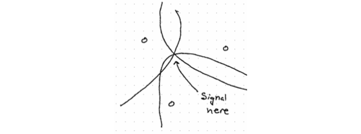
Radio direction finding (RDF) is more-or-less what it says on the tin - if someone is using a radio, how do you find out what direction they're in from where you are right now? If you do that from multiple locations, you can then combine the direction measurements (bearings) to form an estimated location (a process called triangulation). An example triangulation is shown below - if you have two people who know where they are, and what direction the signal is coming from, you can combine those measurements to find an approximate area (the red circle) where the signal is probably coming from.

If you have one bearing, it's homing - which can only "move toward transmitter." More than one bearing is triangulation. For some cases, homing is fine - you just keep moving toward the transmitter until you bump into it. (The classic case is missiles - they just keep flying directly at the transmitter until they hit it.)
There are several general methods for direction finding:
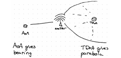
- Power of arrival ("hot/cold" - this isn't really direction finding)
- Angle of arrival
- Amplitude/frequency/phase analysis
In all of these cases, multipathing is an issue - a signal which has "bounced" off of something makes it seem like the thing it bounced off is the source of the signal rather than the original transmitter.
RDF Techniques
Manual angle of arrival
Wave a directional antenna around, use the recorded amplitude to find a bearing, then check the bearing with a compass. Basically "the signal will be strongest when you point the antenna directly at the transmitter."
Doppler
Rotate an antenna really quickly in a circle and use the doppler shift to determine which direction a signal is coming from. The doppler shift will be zero when the antenna is moving exactly perpendicular to the signal (which it will do for only a very brief moment).
Actually spinning an antenna is... hard, so instead usually an array is used (usually 4 antennas), and the radio very rapidly switches which antenna it is using to simulate spinning - AKA pseudo-doppler.
Doppler is fairly cheap, but it really requires a continuous signal to track - if the signal is going on and off, you won't get a "full rotation" of the antenna and won't be able to get a bearing. It pretty much only works for vertically polarized VHF/UHF signals.
Watson-Watt
Amplitude-based method that uses an Adcock/crossed-loop antenna (sometimes also a crossed monopole or crossed dipole) with a "sense" antenna in the center to measure where incoming signals are strongest. The antennas used essentially have two "axes" - in the image below, four vertical antennas are arranged in pairs with a sense antenna in the middle. A signal coming from due South will be very strong on the N-S axis and very weak on the E-W antenna pair. Comparing the relative strength of the signal on N-S vs E-W vs the central sense antenna will give you a bearing.
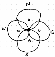
Spacing the elements closer together will improve accuracy, but placing them farther apart increases sensitivity.
This method is well-suited to HF direction finding, and has fast response time with good accuracy and sensitivity, but it doesn't have a way to measure elevation.
Correlative Interferometry (CI)
By placing an odd number of antennas in a circle, it's possible to measure the phase offset of signals coming from various directions. This is accomplished by calibrating the system once it's in place to generate a lookup table (by e.g. generating 360 calibration points as you move a signal around the array).
When a "real" signal crosses the array, take the phase measurements from all the antennas and compare them to the calibration table. Whichever entry in the table correlates best with the measured signal is your bearing, and the strength of the correlation can be used to estimate the quality of the bearing (e.g. how much confidence you should have in it).
CI can cover large bandwidth ranges (>1 GHz), and can use a large antenna diameter which helps with ignoring multipath signals. It can be very accurate (<1 degree), it provides you a measurement of the bearing's confidence/quality, and it can handle cross-polarization without any trouble. Unfortunately, the tolerances for these arrays have to be INCREDIBLY tight. Measuring phase accurately in a way that can be compared between the antennas is extremely difficult and relies on extremely precise time measurement across the antennas.
Time Difference of Arrival (TDoA)
Setting up multiple antennas with a very precise clock lets you determine when a signal reaches each antenna. Using only two antennas, you can determine a curve that a transmitter must be on. (That is, a curved line on the earth where if the transmitter was located anywhere on it, then the measured time difference between the signal arriving at your two antennas would be valid.)
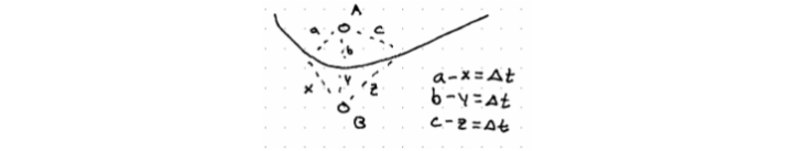
In the image above, delta t represents the time difference between when the signal arrived at the first antenna and the second antenna. Since we know the speed of the signal (the speed of light), we can calculate how much closer the transmitter is to antenna A than B based on how much longer it took to reach the second antenna. Unfortunately, that results in a set of possible solutions - those three equations show three possible solutions, but there is an infinite set anywhere along the curve drawn between the two antennas.
By using three "stations" - each one a pair of antennas as above - the curves can be combined to figure out the location of the transmitter. Adding more stations (up to about 6) generally increases accuracy. This setup requires a central computer that can combine measurements from the stations - which requires extremely precise time measurements to compare! The central brain computes a cross-correlation between the signals at each station to determine delta t and generate a curve, then overlays the curves to get a location. Note that if you're trying to track a continuous signal (something that's just a repeating wave) this correlation is difficult because the wave has no features to compare!
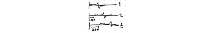
The correlation above is done per-station, so each of the three graphs would be from a single antenna. The computed $\Delta t$ is used to determine how far the signal must be from each antenna, which generates a curve of possible locations that would satisfy the actual measurement.
TDoA doesn't require any special antennas, and is resistant to multipath, but requires extremely precise time and location data for all the antennas. It also requires a lot of sensors to get good accuracy and coverage.
Hybrid
Combining multiple methods - such as a single bearing from an angle of arrival sensor with a single curve from a time difference of arrival sensor - can give good results depending on the strengths of each method and the RF environment.
Countering RDF
There are a few broad methods - deliberately generating multipath can confuse direction-finding equipment since the signal will appear to have multiple sources and determining the original one can be difficult.
"Chirping," or sending transmissions in short bursts, can prevent DF equipment from having enough time to take a measurement of your signal.
Staying on the move (aka "radiate and run") doesn't prevent someone finding where you transmitted from... it's just that you're no longer there by the time they figure it out.
Lastly, using a frequency-hopping spread-spectrum radio protocol can make direction-finding difficult. Explaining why is sorta beyond the scope of this document, but it's an option.
Summary
Radio direction finding can be accomplished with a variety of methods:
- Angle of arrival (AoA)
- Doppler
- Watson-Watt
- Correlative interferometry (CI)
- Time difference of arrival (TDoA)
- Some hybrid of the above
To counter RDF, try:
- Deliberately causing multipathing
- Short burst transmissions
- Staying on the move
- Use frequency-hopping spread-spectrum radio protocols
If you want a deeper introduction to these methods, this document is based on a talk from the Association of Old Crows, which you can find here:
https://vimeo.com/503624323/9f9996b29a
Thanks for reading!