
Understanding stress and strain is essential in designing safe and efficient structures. Mohr’s Circle is a graphical tool that simplifies the process of analyzing stress and strain for two-dimensional transformations. In this article, we will discuss the concept of Mohr’s Circle, its equations for plane stress and plane strain, and how it can be used in analyzing and designing structures subjected to complex loading conditions.
Mohr’s Circle Explained
To design safe and efficient structures, it is important to understand stress and strain. Stress refers to the internal force experienced by a material, while strain refers to the deformation or change in shape caused by that force.
In solid mechanics, the general state of stress at a point is characterized by six independent normal and shear stress components that act on the faces of an element of material located at that point. Similarly, the general state of strain can be represented by the same number of normal and shear strain components that tend to deform each face of an element of the material.
In both cases, the normal and shear components at a point can vary depending on the orientation of the element. Therefore, it is important to understand how the magnitudes of these components change when the element is oriented differently. This process of determining the stress and strain components at different orientations is called stress and strain transformation.

Elevate Your Engineering With Excel
Advance in Excel with engineering-focused training that equips you with the skills to streamline projects and accelerate your career.
Stress and strain transformation can generally be done using mathematical equations. However, there is a graphical tool that simplifies the process for two-dimensional transformations— this is called the Mohr’s Circle.
Mohr’s circle is a graphical representation used to determine the state of stress or strain at a point in a material. The circle is used to visualize the relationship between the normal and shear components acting on a material element at different orientations. It is named after Christian Otto Mohr, who first introduced the concept in 1882.
The circle is drawn by plotting the normal component on the x-axis and the shear component on the y-axis. The center of the circle is located at the average normal component, and the radius of the circle is equal to the maximum shear component. The circle is especially helpful in determining the maximum and minimum normal and shear components, as well as the orientation of the element at which they occur.
Mohr’s Circle is used to analyze and design structures subjected to complex loading conditions, such as bridges, buildings, and machine components. Additionally, it can assist in predicting material failure, allowing engineers to make informed decisions on material selection and safety factors.
Mohr’s Circle Equations for Plane Stress
Suppose we have an initial state of stress within a material defined by the normal stresses 𝜎x and 𝜎y, as well as the shear stress 𝜏xy. The goal is to find the transformed stresses 𝜎x’ and 𝜎y’, and the transformed shear stress 𝜏x’y’ on any inclined plane with an angle 𝜃 with respect to the original coordinate system.
The first step in constructing Mohr’s Circle is to determine the center of the circle, called point C, which represents the average normal stress. This can be computed using the following formula:
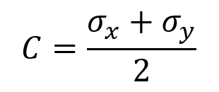
Where:
- C = center of the circle, corresponding to the average normal stress [Pa]
- σx = initial normal stress along the x axis [Pa]
- σy = initial normal stress along the y axis [Pa]
Next, the radius of the circle, R, which represents the maximum shear stress, can be found using the stress values:
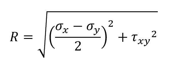
Where:
- R = radius of the circle, corresponding to the maximum shear stress [Pa]
- τxy = initial shear stress [Pa]
Now, we can plot the circle on a 𝜎-𝜏 plane, with the center C and radius R, as shown in the diagram below. The horizontal axis represents normal stresses, while the vertical axis represents shear stresses.
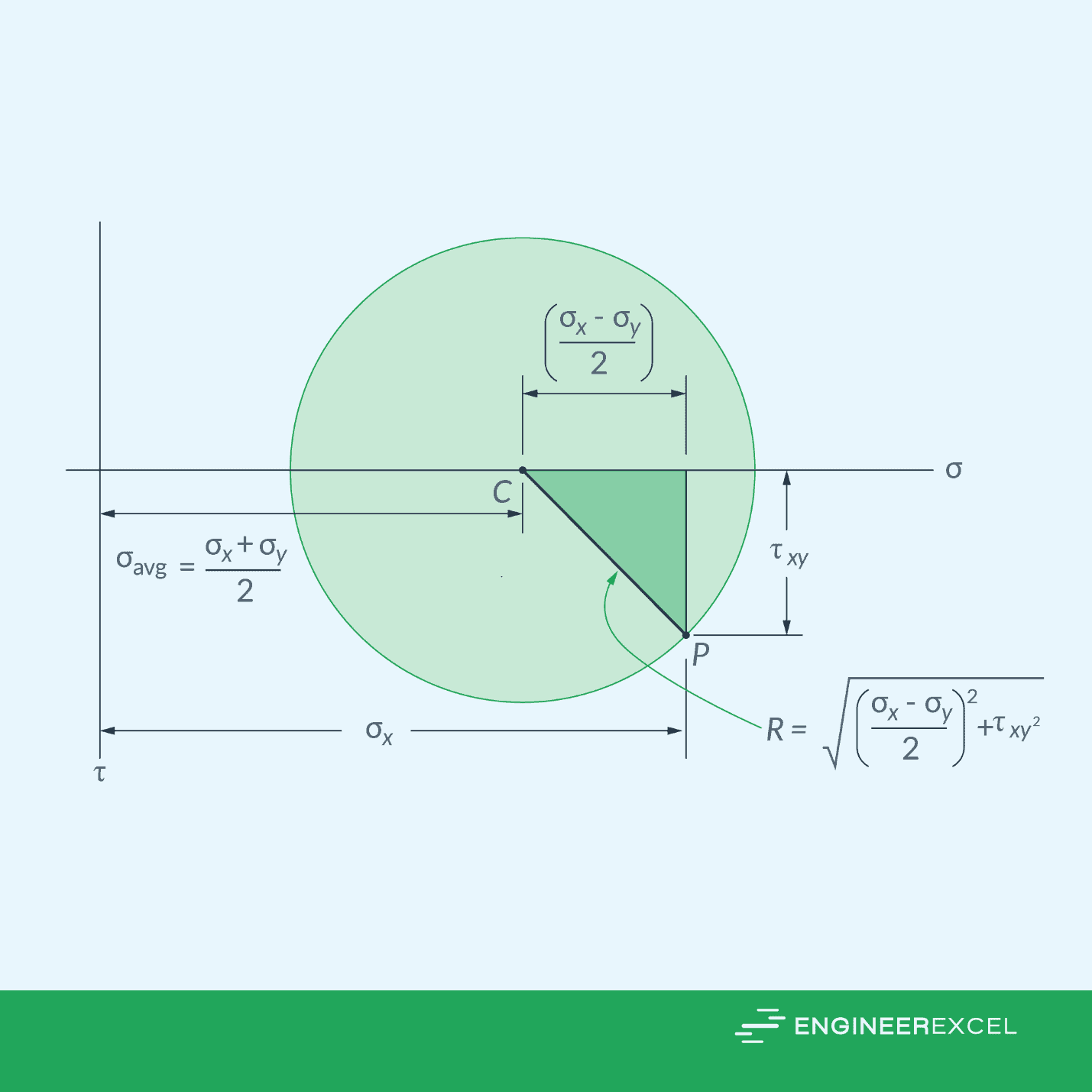
After constructing the circle, the initial reference point, P, can be plotted having coordinates P(σx, τxy). This point represents the initial shear stress and normal stress along x axis, which also represents θ = 0.
Each point on the Mohr’s circle represents two stress components acting on a side of the element defined by the axis, when the axis is in a specific direction θ with respect to the reference point. However, note that a rotation on the Mohr’s circle will correspond to only half of the rotation on the actual element in the same direction.
Mohr’s Circle for Plane Strain
Similar to plane stress, Mohr’s Circle can be used the same way for plane strain.
Suppose we have an initial state of strain defined by the normal strains εx and εy, as well as the shear strain γxy. The goal is to find the transformed strains εx’ and εy’, and γx’y’ on an inclined plane with an angle 𝜃 relative to the reference plane.
The center of the circle, C, represents the average normal strain, which can be computed using the following formula:
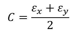
Where:
- C = center of the circle, corresponding to the average normal strain [unitless]
- εx = initial normal strain along the x axis [unitless]
- εy = initial normal strain along the y axis [unitless]
Then, the radius of the circle, R, can be found using the following formula:
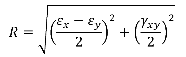
Where:
- R = radius of the circle [unitless]
- γxy = initial shear strain [unitless]
Now, we can plot the circle on a plane, with the center C and radius R, as shown in the diagram below. The horizontal axis represents normal strain, while the vertical axis represents half of the shear strain.
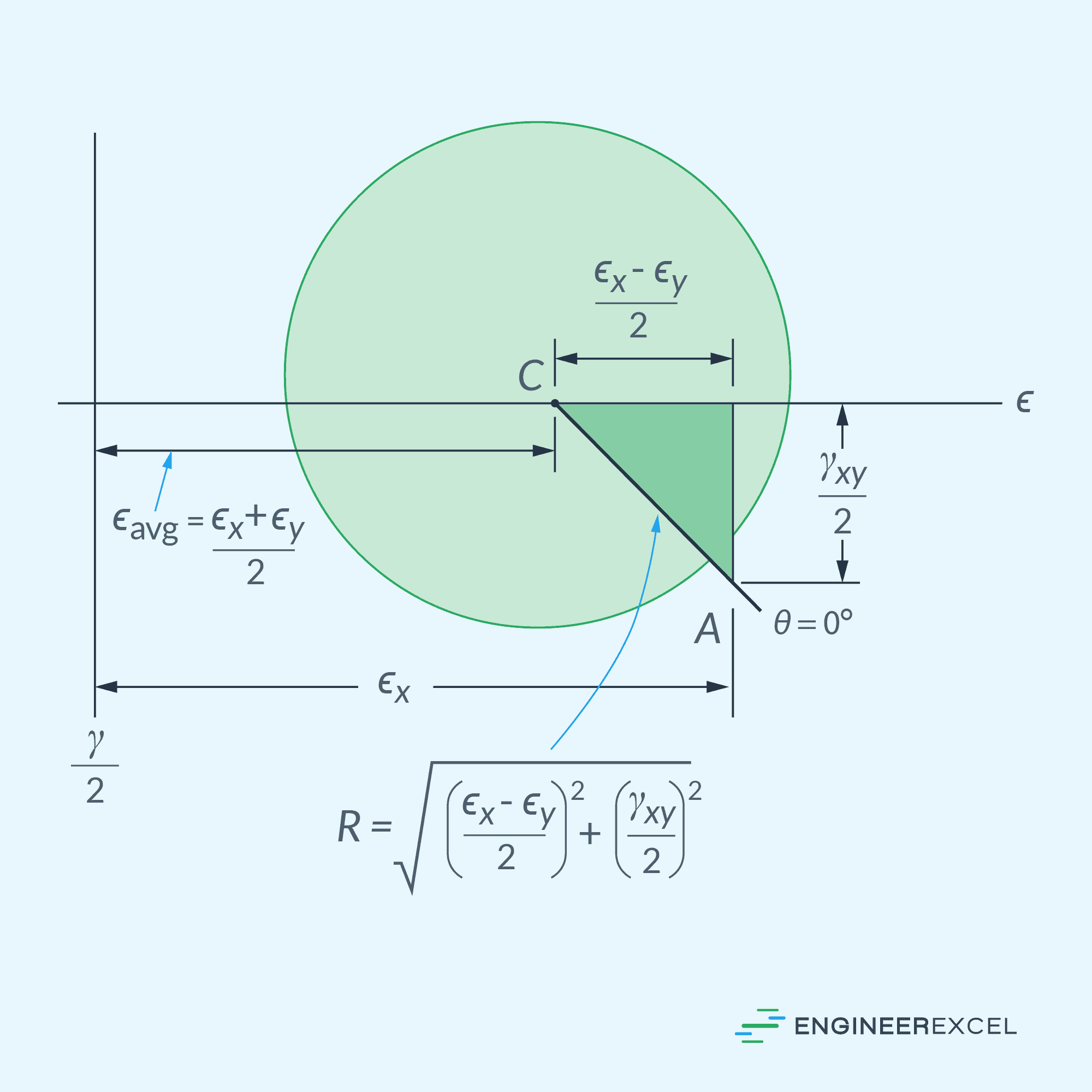
The initial reference point is located at A(εx, γxy/2), representing the initial normal strain and half of the shear strain. This is designated as θ = 0.
The Mohr’s circle for strain can be utilized in a similar manner as the Mohr’s circle for stress.