Abstract
Aims: Mechanisms of lumen compromise after provisional side branch (SB) stenting are poorly understood. In this study we aimed to investigate the impact of bifurcation angle, plaque composition, and procedural strategy on SB compromise.
Methods and results: Computer simulations of stent implantation were performed in Medina (1,1,1) bifurcation models. Provisional SB stenting was replicated including post-dilation after main branch stenting. Two bifurcation angles (45°, 70°) and four plaque types (fully lipid, fully fibrous, lipid with half and fully calcified ring distal to the carina) were tested. Two post-dilation balloons of different lengths (15 mm and 9 mm) were also investigated. Provisional stenting caused an ovalisation of the SB ostium (i.e., increase of ellipticity from 0.27 to 0.58±0.21, p<0.05) that might appear as a significant stenosis on two-dimensional angiography, although SB ostium area was preserved (–3.3±10.3%) in the absence of calcifications. However, in the presence of calcifications, SB lumen volume compromise was evident (–0.89±0.15 mm3). Plaque type had a higher impact than bifurcation angle on SB ostium shape. A shorter balloon (9 mm) for proximal optimisation reduced SB lumen volume compromise from –1.11 mm3 to –0.72 mm3.
Conclusions: Simulations showed ovalisation of the SB ostium, generally without significant lumen compromise. Provisional stenting in the presence of calcifications resulted in a more severe outcome for the SB ostium.
Introduction
Coronary bifurcation lesions, which account for approximately 15-20% of total coronary lesions, represent a challenge in percutaneous coronary intervention in terms of both procedural success rate and long-term cardiac events1. Currently, the standard of care to treat a bifurcation lesion is the provisional side branch (PSB) approach1. A potential complication of this procedure is the aggravation of side branch (SB) ostial stenosis after stent implantation in the main branch (MB)1,2 and the associated increased risk of periprocedural myocardial infarction3-5.
SB ostium compromise after PSB has been attributed to plaque shift from the MB into the SB6 or to the shift of the carina into the SB7-10. Several potential predictors of SB ostium occlusion after MB stenting, including SB lumen diameter11, distal bifurcation angle5,9,12, MB calcified plaque13, SB plaque length4 and thickness11, have been identified. However, the exact contribution of bifurcation and lesion characteristics to SB occlusion has not been fully clarified since the results have been contradictory. The intrinsic difficulties in the interpretation of the diagnostic tools, without an exhaustive understanding of the mechanics of the stenting procedure, can bias the results and might provide only a fragmentary explanation of suboptimal or catastrophic outcomes.
Computer simulations can reproduce, in a three-dimensional controlled environment, controversial “what if” scenarios to elucidate the underlying process of the events occurring during the stenting procedure14,15. In this study, computational modelling of PSB stenting with post-dilation was used to study the impact of distal bifurcation angle and plaque composition on post-procedural SB ostial stenosis.
Methods
STUDY PROCEDURE
Virtual stent implantations were performed using finite element simulations in several different Medina (1,1,1) bifurcation models. The provisional stenting technique was virtually replicated, including post-dilation after MB stenting. Two different bifurcation angles and four different plaque types were tested. Furthermore, the impact of post-dilation balloons with different lengths was investigated.
CORONARY BIFURCATION MODELS
Population-based models of the left anterior descending coronary bifurcation with its first diagonal branch were created in pyFormex (www.nongnu.org/pyformex) (Figure 1A).
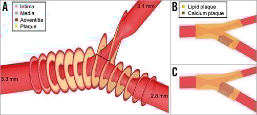
Figure 1. Model of the left anterior descending coronary bifurcation with its first diagonal branch. A) Three-dimensional view of the bifurcation model with overlaid sections at the plaque location. The dashed line indicates the first SB cross-section, closest to the SB ostium and perpendicular to the vessel centreline. B) Position of the 4 mm half calcium ring. C) Position of the 4 mm full calcium ring.
The proximal MB diameter was 3.3 mm16, while the diameters of the distal MB and the SB were set to 2.8 mm and 2.1 mm, respectively, according to Finet’s law17. Two different distal angles in the physiological range, namely 45° and 70°, were used, while the proximal angle was set to 150°18,19. The model was also bent on a sphere with a radius of 56.3 mm20 to account for the curvature of the heart.
The bifurcation lesion was Medina class 1,1,1, with a 60% diameter stenosis in each branch. The lesion was eccentric with the plaque located in the inner curve of the artery. The total lesion length was 12 mm for both branches21, with the ostial portion extending up to 5 mm proximally to justify the use of the single-stenting technique1.
The vessel wall consisted of three layers with realistic material properties of the coronary artery22. Four extreme plaque scenarios were tested: (i) fully lipid, (ii) fully fibrous, (iii) lipid with a 4 mm long half-calcified ring distal to the carina, on the side opposite to the carina (Figure 1B), and (iv) lipid with a 4 mm long calcified ring distal to the carina wrapping the distal MB (Figure 1C). Fibrous and calcium material properties were taken from experimental tests on human atherosclerotic tissues23, while the lipid was modelled as a very soft material24.
A detailed description is provided in the Appendix.
STENT DELIVERY SYSTEM
A MULTI-LINK 8™ stent 3×18 mm (Abbott Vascular, Santa Clara, CA, USA) was virtually implanted in all models to ensure 10% overexpansion in the distal MB. The balloon model was calibrated to reflect the pressure-diameter curve given by the manufacturer. Similarly, post-dilation balloons were modelled emulating the behaviour of: (i) a 3.5×15 mm NC Sprinter® RX non-compliant balloon (Medtronic, Minneapolis, MN, USA), and (ii) a shorter 3.5×9 mm NC Sprinter RX non-compliant balloon (Medtronic), as in the proximal optimisation technique (POT), where a shorter balloon is inflated at the proximal MB prior to the SB1.
VIRTUAL PROVISIONAL SIDE BRANCH STENTING TECHNIQUE
The simulations of stent deployment (Figure 2) were carried out using the finite element software Abaqus/Explicit (Dassault Systèmes Simulia Corp., Johnston, RI, USA). The PSB stenting technique was virtually replicated, including post-dilation after MB stenting. Predilation was not performed.
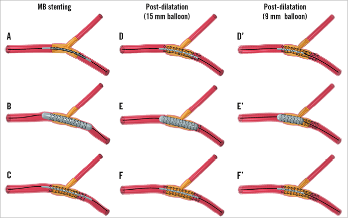
Figure 2. Provisional side branch stenting technique. Main branch (MB) stenting (left panels) followed by post-dilation with a 15 mm (central panels) or a 9 mm (right panels) balloon. Each step consists of balloon positioning (A, D, and D’), expansion (B, E, and E’), and release (C, F, and F’).
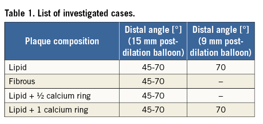
All cases were treated with a 3.5×15 mm post-dilation balloon, which covered the proximal part of the stent and the entire plaque at the MB. Since in clinical practice proximal optimisation by post-dilation is performed with shorter balloons, the cases of 70° distal angle with fully lipid plaque and fully calcified ring were treated with a 3.5×9 mm balloon as an alternative (Figure 2D’-Figure 2F’) to investigate the possible benefits of a shorter balloon size on critical outcomes. This shorter balloon was positioned in the MB to cover the proximal portion of the stent and the plaque up to the SB.
A total of 10 simulations werre carried out (Table 1) with a similar procedure to that previously described25,26.
ANALYSIS OF THE RESULTS
The effect of the stenting procedure on SB ostium compromise was investigated by analysing geometrical changes of the SB. Post-processing was performed in pyFormex. The first SB cross-section (Figure 1A), closest to the SB ostium and perpendicular to the SB centreline, was assessed pre-procedurally, post MB stenting, and post dilation. The following quantities were computed:
– Lumen area and its change after each procedural step, expressed as percentage.
– Minimum lumen diameter (Dmin) and its change after each procedural step, expressed as percentage.
– Maximum lumen diameter (Dmax) and its change after each procedural step, expressed as percentage.
– Absolute value of ellipticity (1-Dmin/Dmax), as a measure of cross-section ovalisation, and its change after each procedural step, expressed as percentage. The ellipticity ranges between 0 and 1, 0 being a perfect circle, while an increase of the value indicates that the lumen is becoming more oval.
SB ostium compromise was also investigated by volumetric analysis8. The lumen volume of an SB segment of 5 mm from the SB ostium was computed. The SB ostium compromise was defined as the post-procedural lumen volume decrease in the SB ostium segment8.
STATISTICAL ANALYSIS
Statistical analysis was performed in SPSS Statistics, Version 21.0.0.1 (IBM Corp., Armonk, NY, USA). The data were tested for a normal distribution using a one-sample Kolmogorov-Smirnov test and, if so, reported as mean±SD. A one-sample t-test or paired t-test was used for testing differences for normally distributed data. Differences among the results for bifurcations with an angle of 45° versus 70° were tested using a non-parametric Mann-Whitney test. For subgroup analysis with fewer than five data points, statistical tests are not suitable to be considered conclusive and, since this study comprises computational data, the observed changes can be considered as representative for these cases. A value of p<0.05 was considered significant.
Results
DISTAL BIFURCATION ANGLE (15 MM POST-DILATION BALLOON)
On average, the PSB stenting technique lowered the distal angle by 8.0±4.1° (–13.6±5.9%, p<0.05). After each step of the PSB procedure, a significant reduction in bifurcation angle was observed (p<0.05), to which MB stenting (–7.0±3.5°) contributed the most. The cases with a preoperative distal angle of 45° (Figure 3A) showed a lower reduction in angle compared to the cases with a distal angle of 70° (Figure 3B) (–5.3±3.3° versus –10.8±3.0°, p<0.05).
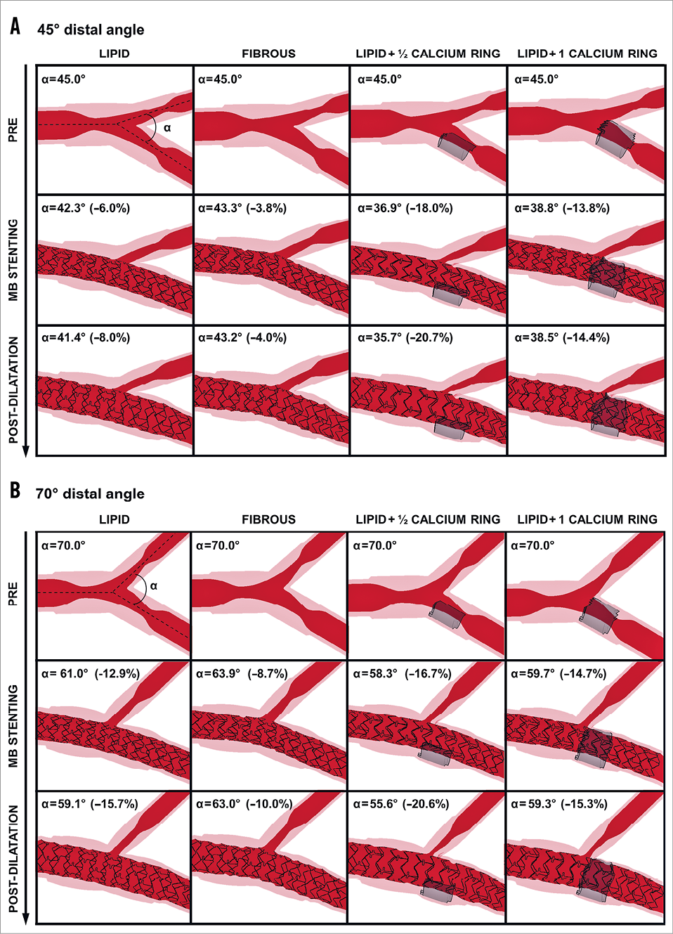
Figure 3. Angiographic-like views at each procedural step. Cases with A) 45° and B) 70° distal angle. (pre: preoperative configuration; MB stenting: main branch stenting; post-dilatation with a 15 mm balloon). Location of the calcification is indicated in grey when present. Absolute distal angles and percentage change from the baseline are indicated.
Regarding plaque composition, the cases with fibrous plaque were characterised by the lowest distal angle reduction (–1.8° and –7.0° for 45° and 70° distal angle, respectively), while those with half-calcified ring plaque exhibited the highest reduction in distal angle (–9.3° and –14.4° for 45° and 70° distal angle, respectively).
SIDE BRANCH AREA AND OSTIAL SHAPE (15 MM POST-DILATION BALLOON)
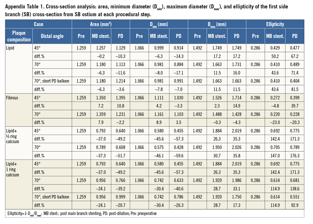
The PSB stenting technique caused an ovalisation of the SB lumen in all cases except those with fibrous plaque where ovalisation was minimal or absent (Figure 4). To quantify this occurrence, the area, the minimum and maximum diameter, and the ellipticity of the first SB cross-section were calculated. All absolute and relative values are reported in Appendix Table 1.
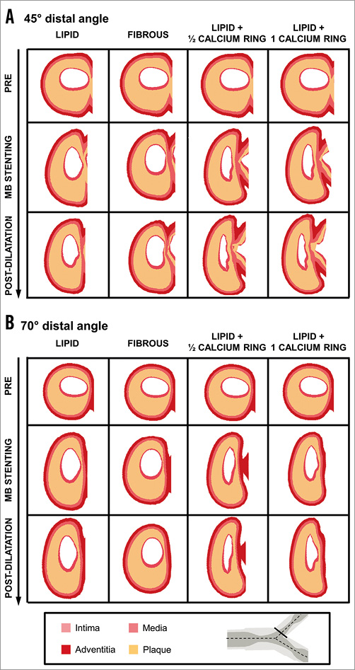
Figure 4. First side branch cross-sections for the cases with 45° and 70° distal angles at each procedural step (pre: preoperative configuration; MB stenting: main branch stenting; post-dilation with a 15 mm balloon). A) 45° distal angle. B) 70° distal angle. A solid line in the bifurcation schematic indicates the location of the investigated cross-sections.
The area was decreased, on average, by 25.3±24.7% (p<0.05) after stenting (–24.5±29.8% and –26.2%±23.1% for the cases with 45° and 70° distal angles, respectively, p=NS). The plaque composition minimally influenced the final post-PSB area size, except for the calcified plaque cases where the area reduction reached 47.3±5.5% (Figure 5A).
Lumen ovalisation was confirmed by a significant decrease in minimum diameter by 30.8±26.0% (p<0.05) (Figure 5B), a significant increase in maximum diameter of 22.9±14.5% (p<0.05) (Figure 5C) and ellipticity of 101.9±73.1% (p<0.05) (Figure 5D). The ovalisation increased significantly after each procedural step. Although the change in minimum and maximum diameter and ellipticity did not differ greatly between cases with different distal angle (p=NS), larger differences were found between cases of different plaque compositions with the same distal angle. In particular, ovalisation was more evident in the presence of calcifications which showed a higher increase of ellipticity (164.4±17.3%) compared to cases with fully lipid plaque (69.3±2.9%) and fibrous plaque, where the increment of ellipticity was limited for 45° distal angle (39.6%) or absent for 70° distal angle (Figure 5D). The extent of the calcification did not seem to have a great impact on the ovalisation, thus leading to similar results in cases with full or half calcium ring (154.9±23.1% versus 173.8±3.5%, respectively) (Figure 5D).
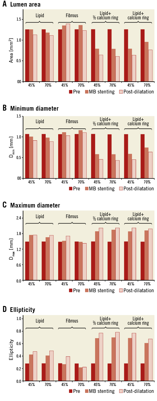
Figure 5. Analysis of the first side branch cross-section for all cases treated with a 15 mm post-dilation balloon (preoperative, post main branch [MB] stenting, and post-dilation values). A) Lumen area. B) Minimum diameter (Dmin). C) Maximum diameter (Dmax). D) Ellipticity.
SIDE BRANCH LUMEN VOLUME (15 MM POST-DILATION BALLOON)
SB compromise, assessed as changes in SB lumen volume, was negligible for cases with fully lipid and fibrous plaques, with values varying around zero, while it became more severe in the presence of calcifications (values lower than –0.8 mm3) (Figure 6). SB compromise was aggravated after each procedural step. The distal angle did not influence the SB compromise except for the cases with full calcium ring (–0.82 mm3 versus –1.11 mm3 for cases with 45° and 70° distal angles, respectively).
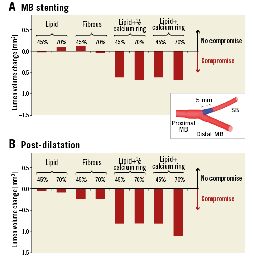
Figure 6. Side branch ostium compromise after main branch (MB) stenting and post-dilation with the 15 mm balloon. A) MB stenting. B) Post-dilation. A decrease of volume is indicative of side branch (SB) narrowing. The SB segment for the lumen volume calculation is indicated in blue in the bifurcation schematic.
COMPARISON OF 9 MM VERSUS 15 MM POST-DILATION BALLOON
The use of a 9 mm post-dilation balloon instead of a 15 mm balloon showed that the procedure had less impact on SB ostium luminal changes. In particular, the shorter balloon was associated with lower reduction of the area (–3.6% versus –11.6% for fully lipid plaque cases and –20.7% versus –39.2% for cases with full calcium ring) (Figure 7A), lower reduction of the minimum diameter (–7.0% versus –17.1% for fully lipid plaques and –26.3% versus –40.6% for cases with full calcium ring) (Figure 7B), lower increase of the maximum diameter (11.5% versus 16.0% for fully lipid plaques and 17.3% versus 33.1% for cases with full calcium ring) (Figure 7C), and lower increase of the ellipticity (41.5% versus 71.4% for cases with fully lipid plaque and 92.9% versus 138.6% for cases with full calcium ring) (Figure 7C), and lower reduction of the ellipticity (–16.5% versus –28.4% for cases with fully lipid plaque and –37.1% versus –55.3% for cases with full calcium ring) (Figure 7D). Furthermore, SB ostium volumetric compromise after post-dilation with a 9 mm balloon was not present in the case with fully lipid plaque and was attenuated in the case with full calcium ring (–0.72 mm3 for 9 mm versus –1.11 mm3 for 15 mm post-dilation balloon) (Figure 8).
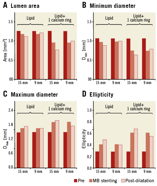
Figure 7. Comparisons of the first side branch cross-section obtained after the expansion of 15 mm and 9 mm post-dilation balloons. A) Lumen area. B) Minimum diameter (Dmin). C) Maximum diameter (Dmax). D) Ellipticity.
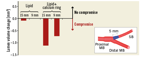
Figure 8. Comparison of side branch ostium compromise caused by the expansion of 15 mm and 9 mm long post-dilation balloons. A decrease of volume is indicative of side branch (SB) narrowing. The SB segment for the lumen volume calculation is indicated in blue in the bifurcation schematic.
Discussion
In the current study, we performed computer simulations to understand the role of distal bifurcation angle, plaque type, and procedural strategy in SB compromise after provisional stenting of coronary bifurcation lesions. The main findings were that: (i) distal bifurcation angle had a minimal impact on geometric changes of the SB ostium; (ii) plaque type, and especially the presence of calcium, highly influenced the changes in shape and dimensions of the SB ostium by inducing an elliptic lumen cross-section and reducing the lumen area; and (iii) the use of a shorter balloon during post-dilation was associated with lower SB compromise.
Stent implantation over a bifurcation lesion with or without subsequent post-dilation might induce geometrical changes of the SB ostium leading to observations of angiographic SB compromise during the procedure. These geometrical changes appear to be the combination of two effects: (i) the straightening of the MB that stretches the SB, and (ii) the displacement of the carina towards the SB because of stent expansion7-10,27, confirming observations of other numerical studies on single patients26,28. Although angiographic images might demonstrate a significant lumen compromise, this is rarely accompanied by a haemodynamically significant compromise, as demonstrated by post-implantation FFR measurements of the SB7. This can be attributed to limitations of the angiography to depict a three-dimensional structure properly in two dimensions. This study demonstrated that, although the lumen area of the SB ostium was minimally affected, there might be significant changes in the shape of the SB ostium, including the shift between the short and the long axis of the bifurcation (Figure 4), and the ovalisation of the SB ostium. As the angiographic projections can mask the major axis of the elliptical lumen, while giving an estimate of the minor axis of the lumen, they fail to depict meticulously the real vasculature changes occurring due to the intervention.
Additionally, some cases also demonstrated SB lumen compromise. Through different models, we investigated the impact of two major factors –distal bifurcation angle and plaque composition– on the potential lumen compromise. According to our simulations, the bifurcation angle had no significant impact on SB ostium area or SB volume reduction after provisional stent implantation and post-dilation, as the differences between these metrics were minimal between cases with 45º or 70º distal bifurcation angles and the same plaque type. Although this result is in line with clinical studies that have found no correlation between the distal angle and the SB compromise4,8,29, other works have identified the presence of a wide5,12 or narrow9,13 distal angle as a potential predictor of SB compromise after MB stenting.
Significant differences were observed based on plaque composition, with fibrous or lipid plaques having nearly unaffected lumen dimensions, and calcified plaques demonstrating important variations of lumen area and volume, irrespective of the distal bifurcation angle. In our virtual implantations, lumen area was not significantly modified for full lipid plaques, as the plaque components were easily squeezed due to the soft properties, whereas in fibrous plaques there was more resistance to the stent expansion, resulting in less ovalisation of the SB ostium. However, in the cases with calcified plaque at the carina, significant SB lumen compromise was observed, supporting previous observations from a study based on OCT measurements13. According to our simulations, the straightening of the vessel due to MB stenting and post-dilation was able to push the entire calcium ring towards the SB, thus annealing the shielding effect of a hard boundary on the distal MB, which may allow the stent to expand on the side of the carina. Thus, in both cases the presence of calcium within the SB was associated with significant distortion of the SB ostium and SB compromise, as clinically observed13.
In this study, we also investigated the impact of post-dilation with non-compliant balloons of different lengths on the geometrical changes of the SB ostium. Although in all cases post-dilation had an incremental effect on top of stent implantation on SB compromise, differences were particularly pronounced with a longer balloon, commonly used in clinical practice to improve expansion of the entire stented segment. Thus, the increased expansion might aggravate a potential intervention-induced SB compromise. Conversely, the use of a shorter post-dilation balloon aiming at optimising expansion at the proximal segment did not further reduce SB ostium area (Figure 7A), even in the difficult setting with calcified plaque. Therefore, strategies such as POT in provisional stenting might be beneficial to improve expansion in challenging proximal segments, while not significantly aggravating a potential SB compromise caused by stent implantation, as previously reported8.
Study limitations
All results were obtained from computer simulations with population-based models. Although patient-specific anatomical and tissue composition are missing, these models allow tuning of specific characteristics (in our case, distal bifurcation angle and plaque composition) and studying their influence on specific occurrences, such as SB compromise, while keeping other variables constant. In this light, the selected extreme plaque scenarios, although they may not occur in vivo, can allow a better understanding of potential clinical outcomes. These simulations did not include modelling of the effect of predilation as, although it is commonly used clinically in the treatment of bifurcations, it would not allow us to study the effect of stent implantation per se.
Conclusions
In our series of virtual stent implantation in bifurcation lesions using a provisional stenting technique with post-dilation, various geometrical changes of the SB ostium were observed, with the main change being an ovalisation of the SB ostium, in the absence of significant lumen compromise in most cases. The presence of calcification in the plaque and the use of a long post-dilation balloon were associated with higher extent of lumen compromise, while the distal bifurcation angle had a minimal impact on SB compromise.
| Impact on daily practice Virtual provisional stenting of coronary bifurcations showed that the main impact of the procedure is an ovalisation of the SB ostium that might appear as a significant stenosis in two-dimensional angiography, without causing an actual reduction of the SB ostium area in the majority of cases. This explains why suboptimal angiographic results of the SB are not necessarily associated with a poor clinical outcome. Moreover, as the type of plaque and particularly the presence of calcification had a significant impact on a potential SB compromise, invasive imaging can be considered before intervention in the bifurcation region for assessment of the plaque type and for evaluating the need for eventual SB protection. Finally, the absence of significant SB compromise with the use of a short post-dilation balloon underscores the potential value of techniques such as POT for the improvement of stent expansion proximally without causing further aggravation of a potential SB stenosis. |
Funding
F. Iannaccone, C. Chiastra, and J.J. Wentzel are supported by the ERC starting grant (310457, BioCCora).
Conflict of interest statement
The authors have no conflicts of interest to declare.
SUPPLEMENTARY DATA
Appendix. Extended methods
CORONARY BIFURCATION MODELS
Population-based models of the left anterior descending coronary bifurcation with its first diagonal branch were created in the open-source software pyFormex (www.nongnu.org/pyformex) (Figure 1A).
The proximal MB diameter was 3.30 mm16, while the diameters of the distal MB and the SB were set to 2.77 mm and 2.10 mm, respectively, according to Finet’s law17. Two different distal angles in the physiological range, namely 45° and 70°, were used18,19,30, while the proximal angle was set to 150°18,19,31. The proximal MB, distal MB, and SB segments were of a sufficient length (30, 25 and 25 mm, respectively) to limit the influence of the fixed boundary condition applied to the terminal sections of the branches. The model was also bent on a sphere with radius of 56.3 mm20 to account for the curvature of the heart.
The bifurcation lesion studied was Medina class 1,1,1, with a 60% diameter stenosis in each branch32. The lesions were eccentric with the plaque located in the inner curve of the artery. The total lesion length was set to 12 mm for both branches21, and the lesion was symmetrically located in each branch with a distance of approximately 6 mm from the centre of the polygon of confluence33. Since the polygon of confluence had a length of about 1 mm, the ostial lesion was extending up to 5 mm proximally, thus justifying the use of the single-stenting technique performed in our study1. In addition, the stenosis accounted for an increased plaque burden due to the outward growth of the plaque in the first stages of the atherosclerotic disease34. In particular, the external diameter of the vessel at the plaque location (Figure 1) was calculated as a percentage of the reference lumen radius, increased by 1/0.774, a value derived from the findings described by van der Waal35. The swelling was not introduced between the distal MB and SB as the plaque grows towards the outside of the bifurcation35,36.
The vessel wall consisted of three layers. Based on IVUS measurements37, the intima-media layer had a thickness equal to 10% of the lumen diameter. The thickness of each layer was derived from the relation provided by Holzapfel et al22: 26%, 35%, and 39% of the total wall thickness for the intima, media, and adventitia, respectively. The material properties of the three-layered arterial wall were retrieved from ex vivo tests as described by Holzapfel et al22. For the plaque composition, four extreme lesion scenarios were tested: (i) fully lipid, (ii) fully fibrous, (iii) lipid with a 4 mm long half calcified ring distal to the carina on the side of the branch opposite to the carina (Figure 1B), and (iv) lipid with a 4 mm long calcified ring distal to the carina wrapping the distal MB (Figure 1C). Fibrous and calcium material properties were taken from experimental tests on different human atherosclerotic tissues23, while the lipid was modelled as a very soft material24. The arterial wall material behaviour was described using a third order Ogden model to catch its non-linear behaviour, though neglecting anisotropy. The plaque components were modelled with a neo-Hookean material model. Fully plastic behaviour was included to emulate roughly the degradation of the arterial wall and rupture of the plaque components.
All vascular models were discretised with linear brick elements with reduced integration (C3D8R in the Abaqus nomenclature) which guarantee sufficient accuracy of both displacements and mechanical quantities such as stress and strain with an adequate seeding. In particular, the number of elements was increased in the longitudinal direction at the stent landing zone to ensure realistic deformation at the region of interest, while keeping acceptable computational time. One element in the radial direction was considered per layer, while the plaque was discretised with four elements in the radial direction, using wedge elements at the connecting regions. The final meshes counted on average 21,500 nodes and 17,200 elements.
The bifurcation was constrained at the border of each branch, allowing only radial displacement.
STENT DELIVERY SYSTEM
A MULTI-LINK 8™ stent 3×18 mm (Abbott Vascular, Santa Clara, CA, USA) was virtually implanted in all models to ensure 10% overexpansion in the distal MB. The stent geometry was discretised with Timoshenko beam elements, while surface elements were used to cover the stent surface and allow a more accurate contact surface for the interactions with the vessel. The stent is fabricated with a cobalt-chromium alloy that was described by a von Mises-Hill plasticity model with isotropic hardening.
The balloon was modelled using the simplifications proposed by Kiousis et al38, employing a cylindrical geometry with an orthotropic material behaviour which ensures circumferential compliance while avoiding significant foreshortening. Although the approximation does not reflect the real unfolding of the delivery system, an accurate calibration reflects the pressure-diameter curve given by the manufacturer. Similarly, post-dilation balloons were modelled emulating the behaviour of: (i) a 3.5×15 mm NC Sprinter® RX non-compliant balloon (Medtronic, Minneapolis, MN, USA), and (ii) a shorter 3.5×9 mm NC Sprinter RX non-compliant balloon (Medtronic), as in the proximal optimisation technique, where a shorter balloon is inflated at the proximal MB prior to the SB1.
The balloons were fixed to a catheter approximated with shell elements with elastic material properties, which was let free to slide over a guidewire simplified with beam elements.
VIRTUAL PROVISIONAL SIDE BRANCH STENTING TECHNIQUE
The simulations of stent deployment (Figure 2) were carried out using the finite element software Abaqus/Explicit (Dassault Systèmes Simulia Corp., Johnston, RI, USA) as quasi-static analyses due to the non-linearity of the material models, large deformations, and complex contact problems39. The PSB stenting technique was virtually replicated, including post-dilation after MB stenting. Predilation was not performed. The following procedure was applied:
The guidewire was bent along the MB centreline using a displacement-driven approach, dragging the stent-balloon system at the target location by enabling contact between the balloon-supporting catheter and the guidewire.
The delivery system was allowed to “relax” inside the lumen to achieve a more realistic configuration and interaction with the vascular structure.
The balloon was inflated to anchor the stent to the lesion.
The balloon was deflated and removed.
The post-dilation balloon was inserted ensuring that the balloon useful zone started at the proximal end of the stent.
Steps (2), (3) and (4) were repeated for the post-dilation balloon.
All cases were treated with a 3.5×15 mm post-dilation balloon, which covered the proximal part of the stent and the entire plaque at the MB. Since in clinical practice proximal optimisation by post-dilation is performed with shorter balloons, the cases of 70° distal angle with fully lipid plaque and fully calcified ring were treated with a 3.5×9 mm balloon as an alternative (Figure 2D’-Figure 2F’) to investigate possible benefits of a shorter balloon size on critical outcomes. This shorter balloon was positioned in the MB to cover the proximal portion of the stent and the plaque up to the SB.
A total of 10 simulations were performed (Table 1).