What is Mutual Inductance?
Mutual Inductance is the interaction of one coil magnetic field on another coil as it induces a voltage in the adjacent coil. It refers not to the sharing of inductance but rather to the interaction of inductance: the electrical behavior of one coil influences the electrical behavior of a nearby coil.
An inductor generates an induced emf within itself as a result of the changing magnetic field around its own turns. When this emf is induced in the same circuit in which the current is changing this effect is called Self-induction (L).
However, when the emf is induced into an adjacent coil situated within the same magnetic field, the emf is said to be induced magnetically, inductively or by Mutual induction (M). Then when two or more coils are magnetically linked together by a common magnetic flux, they are said to have the property of Mutual Inductance.
Mutual Inductance is the basic operating principal of the transformer, motors, generators and any other electrical component that interacts with another magnetic field. Then we can define mutual induction as the current flowing in one coil that induces a voltage in an adjacent coil.
But mutual inductance can also be a bad thing as “stray” or “leakage” inductance from a coil can interfere with the operation of another adjacent component by means of electromagnetic induction, so some form of electrical screening to a ground potential may be required.
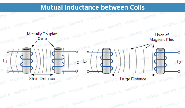
The amount of mutual inductance that links one coil to another depends very much on the relative positioning of the two coils. If one coil is positioned next to the other coil so that their physical distance apart is small, then nearly all of the magnetic flux generated by the first coil will interact with the coil turns of the second coil inducing a relatively large emf and therefore producing a large mutual inductance value.
Likewise, if the two coils are farther apart from each other or at different angles, the amount of induced magnetic flux from the first coil into the second will be weaker producing a much smaller induced emf and therefore a much smaller mutual inductance value. So, the effect of mutual inductance is very much depended upon the relative spacing (S) of the two coils.
Mutual Inductance between Coils
The mutual inductance that exists between the two coils can be greatly increased by positioning them on a common soft iron core or by increasing the number of turns of either coil as would be found in a transformer.
Mutual Inductance between Coils
The mutual inductance that exists between the two coils can be greatly increased by positioning them on a common soft iron core or by increasing the number of turns of either coil as would be found in a transformer.
Unintentional Transformers
- Premise: A component consisting of two adjacent coils of wire is what we call a transformer.
- Premise: A discrete inductor is a coil of wire.
- Ergo, if we place discrete inductors in close proximity we are creating a transformer.
If you consider the extent to which current through a transformer’s primary winding affects the electrical conditions of the secondary winding, the problem readily becomes apparent: discrete inductors can be an effective means of coupling noise and interference from one signal to another. This is especially problematic nowadays when circuits are so compact.
For example, let’s say that you have a small board with a critical sensor signal that must be digitized. You decide to use an LC low-pass for the anti-aliasing filter. The power supply for this board is a switching regulator. In your mind you don’t establish a connection between the anti-aliasing filter and the power-supply circuitry, but since the final device needs to be not much larger than a matchbook, all the parts will end up jammed together on a tiny two-sided PCB.
Before you send the PCB board to fabrication, take a look at which components are located. Did the switcher’s inductor end up right next to the inductor in the anti-aliasing filter? Or maybe they are vertically adjacent, i.e., one inductor is on the top side directly above the other inductor on the bottom side? (The ground plane might reduce the effects of mutual inductance, but physically shielding high-frequency magnetic fields is not so easy.)
If your layout restrictions make it impractical to physically separate inductors, you can “magnetically separate” them by means of the relative orientation. Magnetic coupling is maximized when the coils are arranged in parallel. If you have two inductors, make one perpendicular to the other. If you have three inductors in close proximity, two can be perpendicular and the third can be at a 45° angle.
Reducing Inductance
An interesting manifestation of the mutual inductance phenomenon occurs when two “sourcing” and “sinking” portions of a current path are in close proximity. By “sourcing” and “sinking” I mean that one portion of the path has current flowing in the outward direction (i.e., from the source to the load) and the other has current flowing in the inward direction (i.e., from the load back to the source). You can actually reduce the overall inductance of the current path by placing the sourcing and sinking conductors close to each other, and this lower inductance translates to better high-frequency performance.
Reducing (Unwanted) Coupling
The lower-inductance arrangement discussed in the previous section also results in a physically smaller current loop, and this brings additional benefits. The mutual inductance between one current loop and a nearby current loop leads to unintentional coupling. This reminds me of the square-shaped magnetic loop antenna that came with an audio receiver that I had almost twenty years ago. From an electrical perspective, loop antennas are like coils that interact with the magnetic portion of the transmitted electromagnetic signal.
Large loops are good if you’re trying to listen to the radio, but not so good if you’re trying to maintain signal integrity in an electronic device. If you don’t want the signals from one subcircuit mixing with the signals in another subcircuit, you can reduce coupling by reducing mutual inductance, and you can reduce mutual inductance by forming a physically smaller current loop.
Improving Your Interconnections
Have you ever wondered why cables sometimes include numerous ground connections? In some cases, multiple ground wires are needed to safely carry all the return current, but in low-current applications they help to prevent excessive mutual-inductance-based coupling between adjacent conductors.
If there is a large distance between a conductor and the nearest return wire, this conductor’s current path will have a large loop area. The adjacent conductor will also have a loop area of similar size (slightly larger or slightly smaller, depending on where the return wire is). Consequently, the mutual inductance will be high. You can reduce the size of the loops by distributing ground wires throughout the cable, and if you really want to minimize mutual inductance you can pair every signal wire with a return wire.
After reviewed some practical implications of mutual inductance, you really can improve signal integrity and system reliability by keeping this phenomenon in mind as you are designing your PCBs and your interconnects, especially in this age of relentless miniaturization – as devices get smaller, less and less PCB real estate is available for ensuring adequate separation between current loops and inductive components.