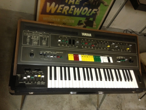
I decided to be ‘one of those guys’ and placed an ad on Craigslist looking for an ARP Odyssey (really want one!!), anyway -responses were thin and expensive except for a ‘broken Yamaha CS-50’. I went for a look and hey-ho next thing I knew I had a $600 CS-50 in the back of my car. Considering perfect ones sell for $1200 – $2000, the price was probably high for how little worked on it, but I decided to take a chance since I like a challenge. It came with a lid and legs.
A good looking specimen. All slider caps are present. The keyboard is in great shape. Not too many scratches. Even came with the legs. The LFO control board has a bunch of paint loss in the lower left corner -like the PO played with a metal band watch on.
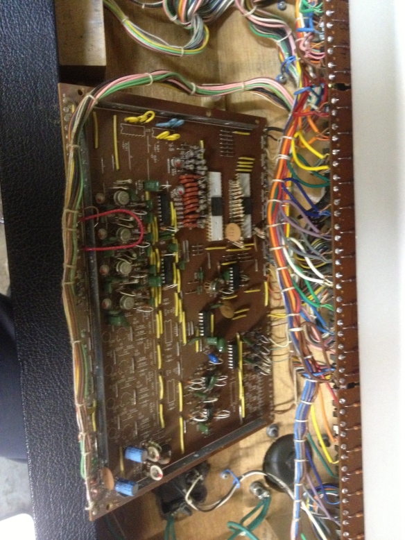
I could get it to make some strange noises at first then they went away. I decided the best approach I could take in trying to make this work was to go through the calibration procedure and replace the perishable components. The procedure starts at the tree trunk with power supply voltages etc and cascades out to the leaves: individual effects on aspects of individual voices. The manual is quite long, but there aren’t all that many settings to change. The perishable components include a bunch of capacitors and CMOS chips. The wisdom on these is to replace them all. We’ll see how that goes. I did an Omni 2, so it can’t be too bad.
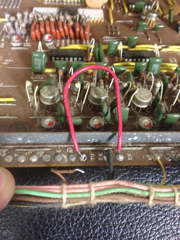
Diving right in. First thing was to get the +15V and -15V rails good. Then there were two others. The fifth one was 4.000 volts to the TU connection on the KAS (key assigner) board. Note the red loop of wire like the outline of a tongue sticking out at nine o’clock. Not supposed to be there soldered to TU.
TU is the tune circuit. EK is the, uhh, um, well, I don’t remember -but it doesn’t have any voltage, so it wont power the tuning circuit. That stray brown wire goes to the TU.
TU is supposed to get 4.000 volts. The divider chip uses this voltage to generate octave and Hz info for notes played. No volts, no notes.
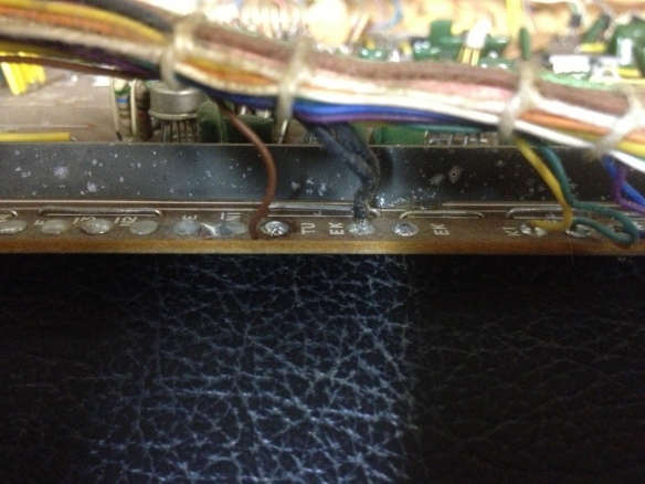
Brown wire soldered back in. I wonder what the last guy was thinking.
Soldering the brown wire back in supplied voltage to the divider and viola! I have notes and octaves and presets -not remotely in tune, but definitely a sign of progress. No matter how I try and adjust VR11 on the SUB board I get 6.46 volts. Time to dive into the pitch circuit that controls the voltage to TU.


