
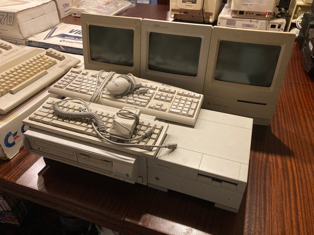
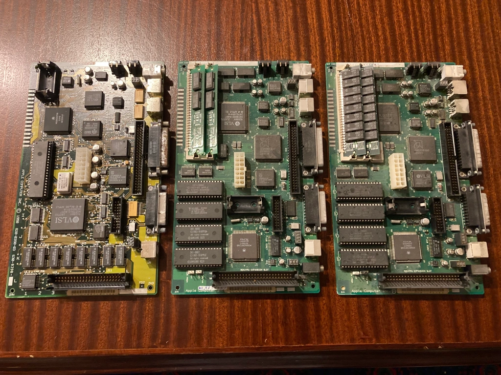
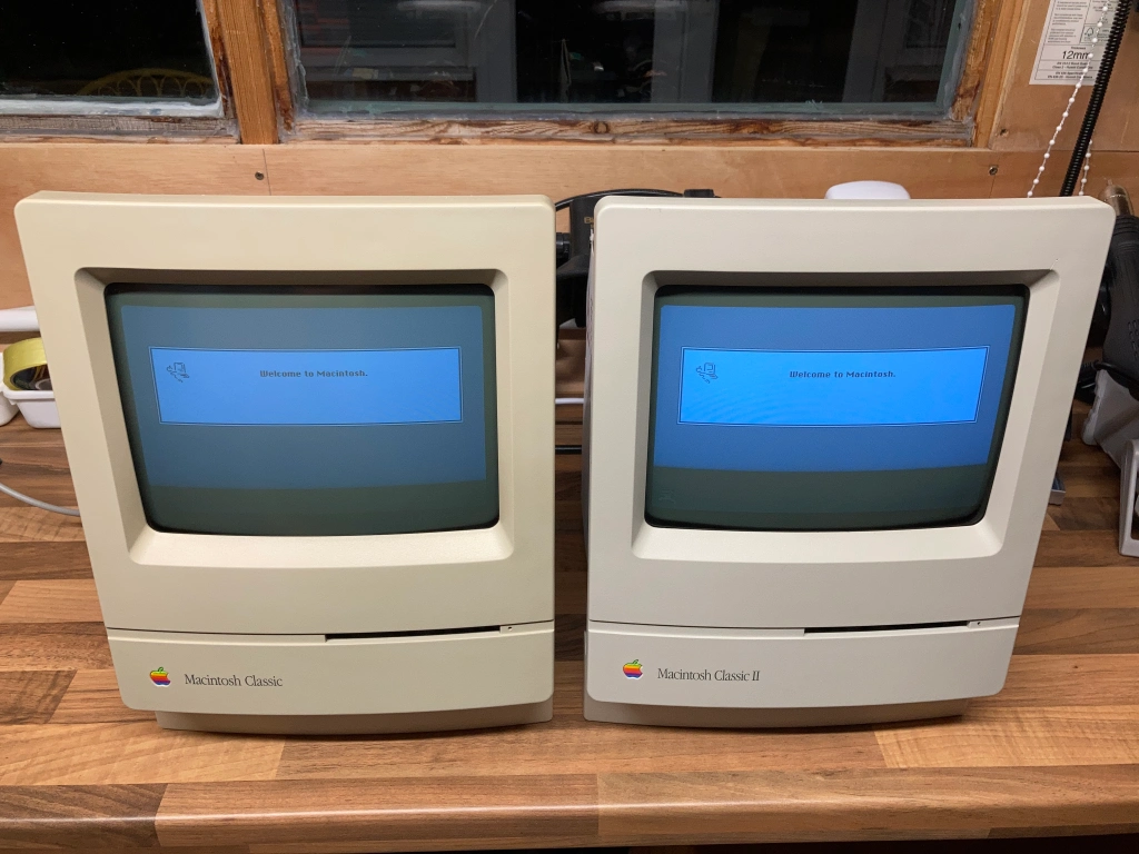
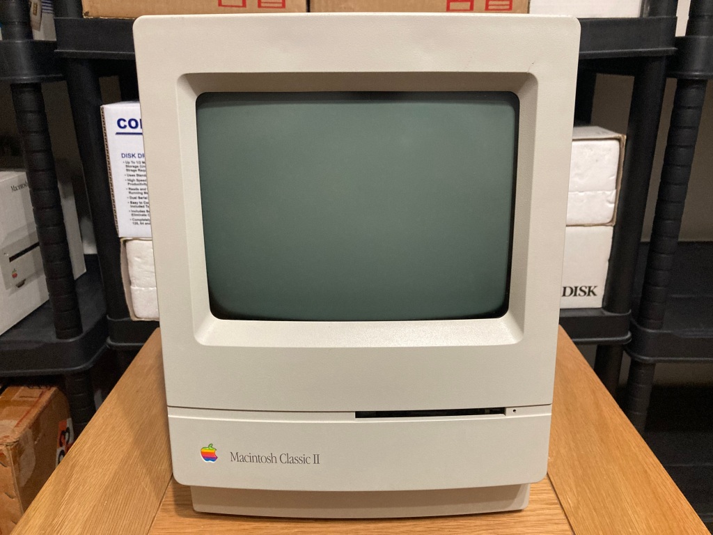
I recently got my hands my first compact Apple Macintoshes, a bundle comprising one 1991 Macintosh Classic I and two 1993 Macintosh Classic IIs, all of which were in unknown non-working condition and required repair.
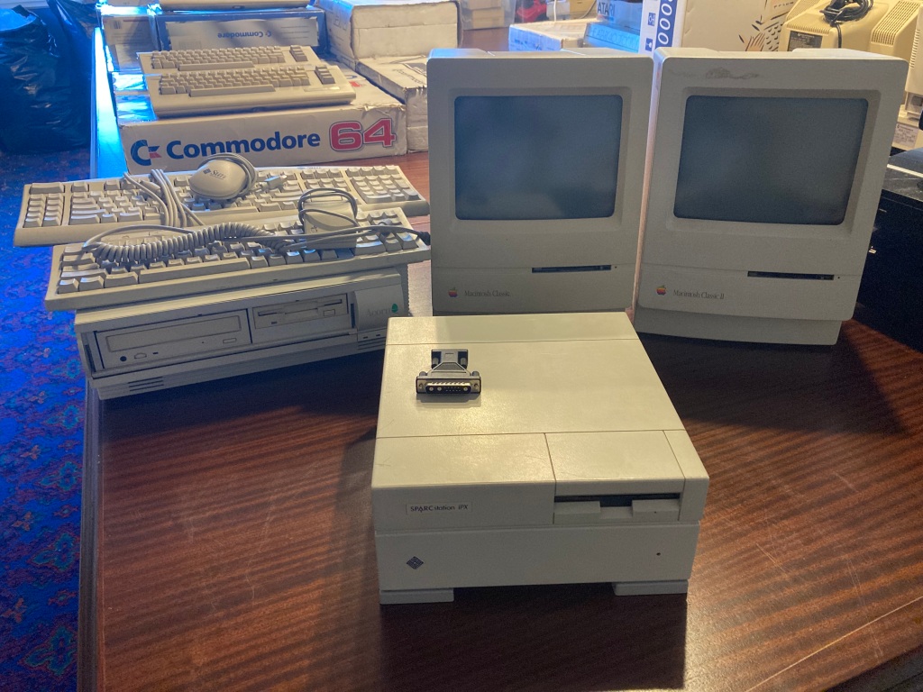
The Macintosh Classic II (also sold as the Performa 200) is a personal computer designed, manufactured and sold by Apple Computer, Inc. Like the Macintosh SE/30, the Classic II featured a 16 MHz Motorola 68030 CPU and 40 or 80 MB HDD, but in contrast to the SE/30, it was limited by a 16-bit data bus (the SE/30 had a 32-bit data bus) and a 10 MB memory ceiling. The slower data bus resulted in the Classic II being 30% slower than the SE/30. Its relative rarity makes it quite collectible.
On its arrival, it seemed to be in good physical condition, but instead of testing it out immediately, I wanted to perform some checks and servicing first.
The Macintosh Classic and Macintosh Classic II both suffer from two major problems: they have a lithium battery in a holder on the mainboard to power the battery-backed PRAM and RTC, and these have a habit of physically leaking corrosive battery alkali (see “battery bomb“) and causing damage to the mainboard and chassis; both the SMD electrolytic capacitors on the mainboard and the through-hole electrolytic capacitors on the analogue board have a habit of failing and physically leaking corrosive electrolyte, which can not only prevent the system from working, but can also cause damage to the circuit boards and the components on them.
I must therefore emphasise: if you have an Apple Macintosh Classic or Classic II in original condition, it needs to be serviced! The original battery needs to be removed, and the original electrolytic capacitors need to be replaced. These systems are dying, day by day.
I wanted to perform this preventative maintenance on the computer (including fitting a new PRAM battery and replacing all of the electrolytic capacitors on the digital board and the analogue board), service the internal 3.5″ 1.4MB floppy disk drive, and replace the internal 3.5″ HDD – then, test everything thoroughly.
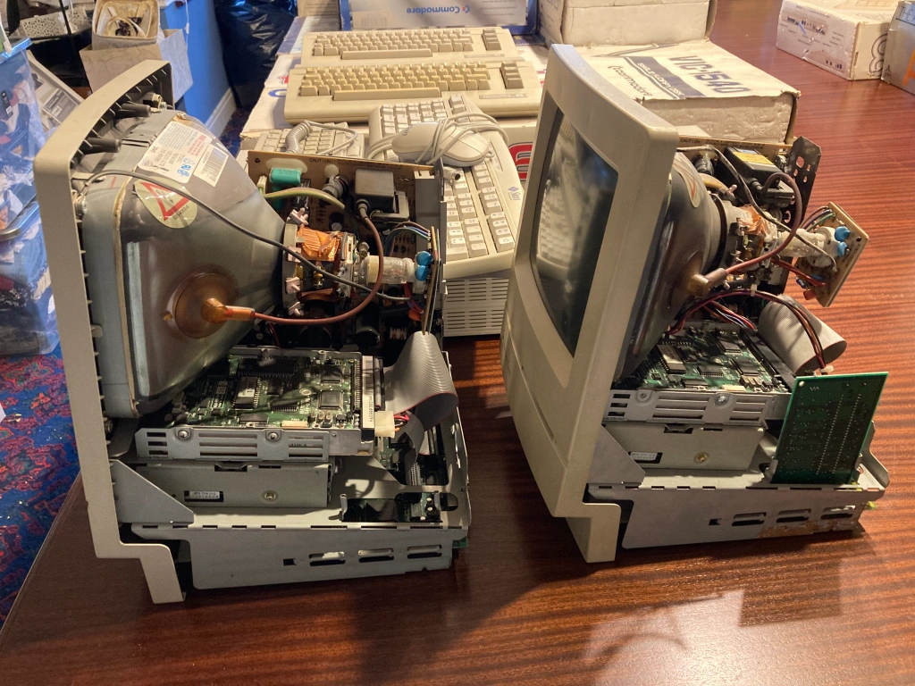
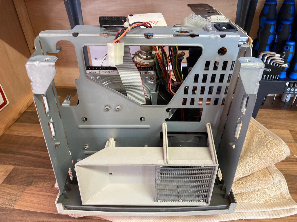
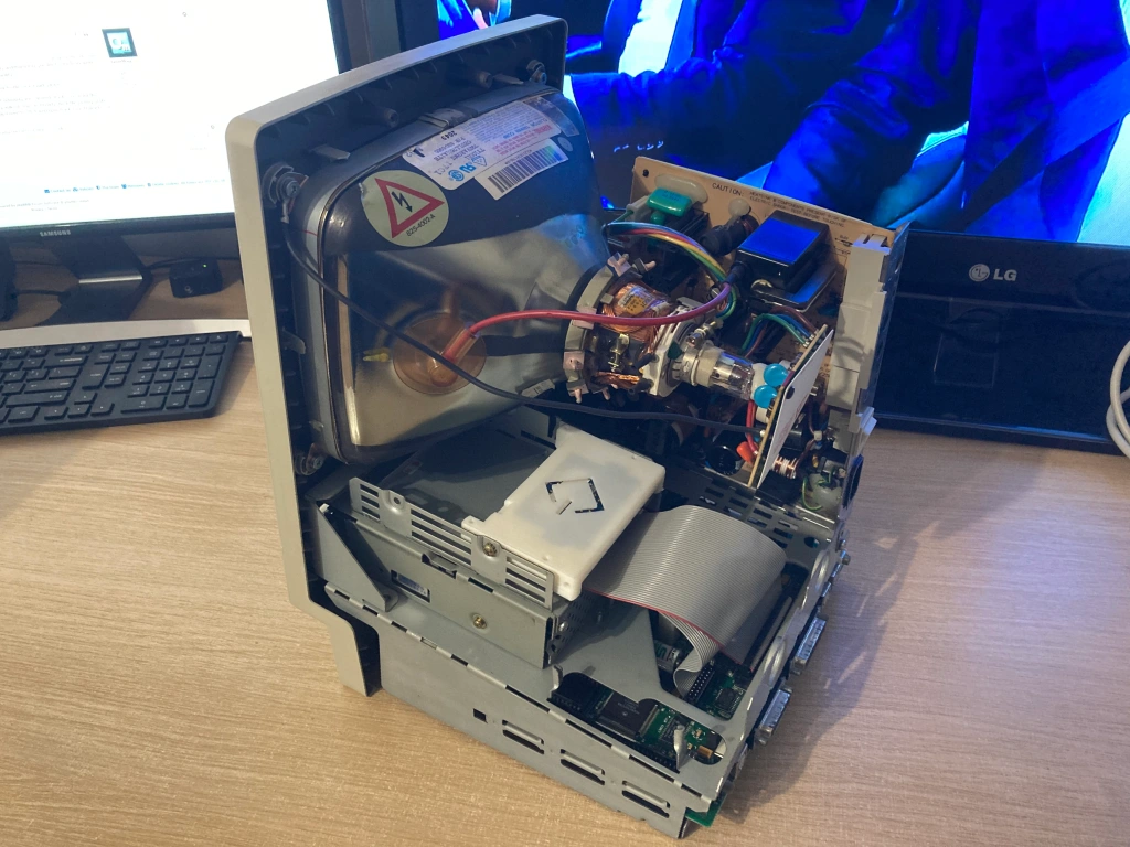
The first step was to disassemble the computer and check over everything inside.
CRT Display Safety
Before we start, a word of warning: like all other mains-voltage electronics, CRTs can be dangerous to work on, so it is important to take care and use the proper precautions – if you don’t know what you’re doing, it’s probably best to leave it to someone who does.
The high voltage side of CRTs can contain extremely high voltages (up to 30 KV for colour displays, less for monochrome), and the “low” voltage side has mains voltage and large line filter capacitors, all of which can give you a nasty shock – most CRTs contain safety features to automatically discharge any stored charge (i.e. bleeder resistors), but even if these exist they can fail, so it’s always best to err on the side of caution.
If you work on a CRT, you do so at your own risk – keep one arm behind your back so as to minimise shock across you torso; if possible, work on the CRT when it is unplugged and powered down, and safely discharge the CRT anode cap before starting work (preferably using a high-impedance lead so as not to damage the CRT interior coating).
Due to a phenomenon known as dielectric absorption, capacitors (including the CRT itself) can self-charge again even after being discharged – if you’re worried about this, keep any potential hazards shorted out while you’re working.
If you do need to work on the CRT while it’s powered up (for example, whilst measuring voltages or making control adjustments), use insulated tools and an isolation transformer.
Disassembling the Mac Classic II
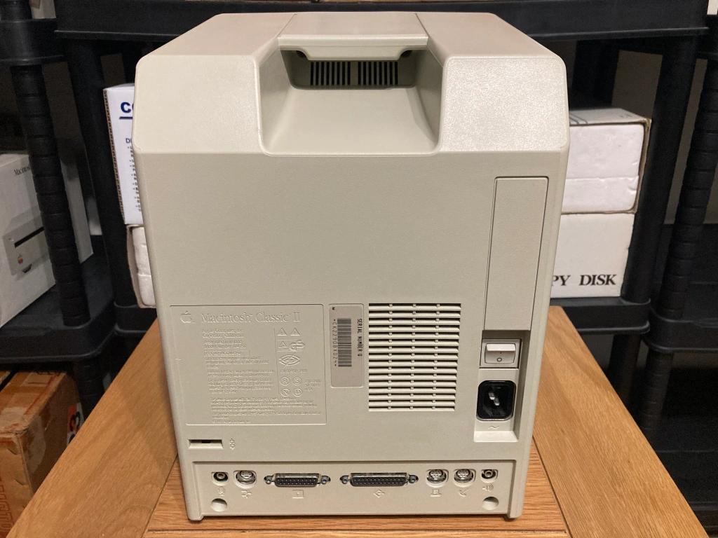
The Mac Classic II is easy to dismantle with basic tools: there are four torx T15 screws holding the rear case in place, two near the mainboard ports at the bottom rear, and two inside the carry handle recess at the top rear (which will need a long screwdriver bit to access).
With the case opened, you get your first look inside the computer – this Mac Classic II seemed complete and all original, just very dusty.
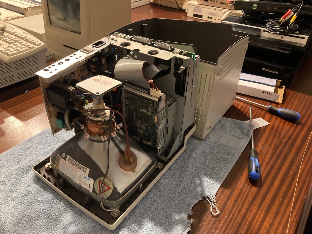
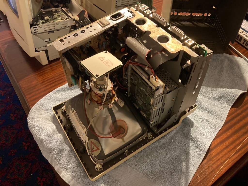
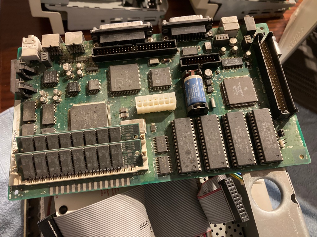
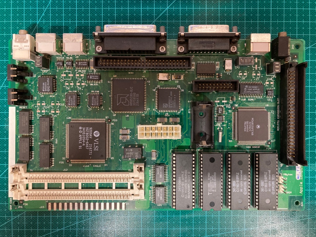
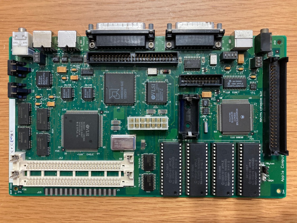
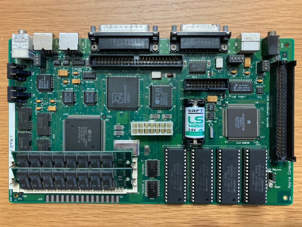
The digital board can be slid out along its two holding rails – its connections to the analogue board, floppy drive, and hard drive can be disconnected, and the board removed.
Thankfully, the PRAM battery had not leaked, so I removed it immediately – however, the SMD electrolytic capacitors on the digital board had clearly already started to leak.
The analogue board is held in place with a single cross-head screw (near the IEC mains connector), the CRT neckboard, a connector to the digital board, and a connector to the CRT yoke – these connectors can be very stiff, and need to be removed very carefully as to prevent damage to the CRT neck and cabling.
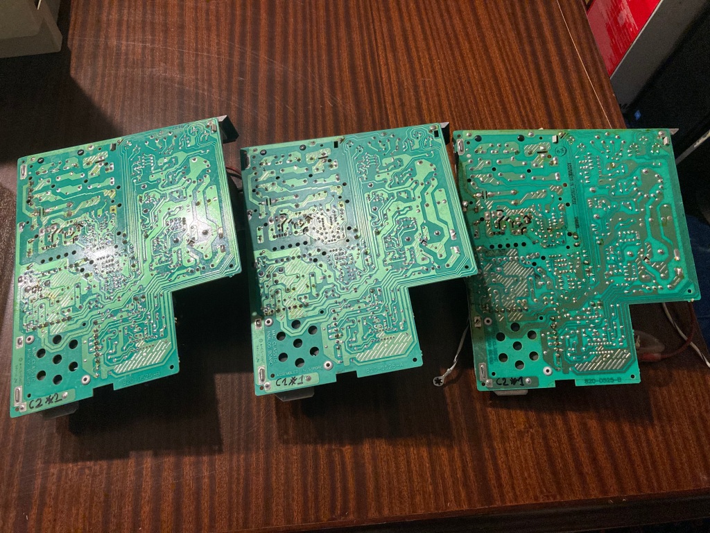
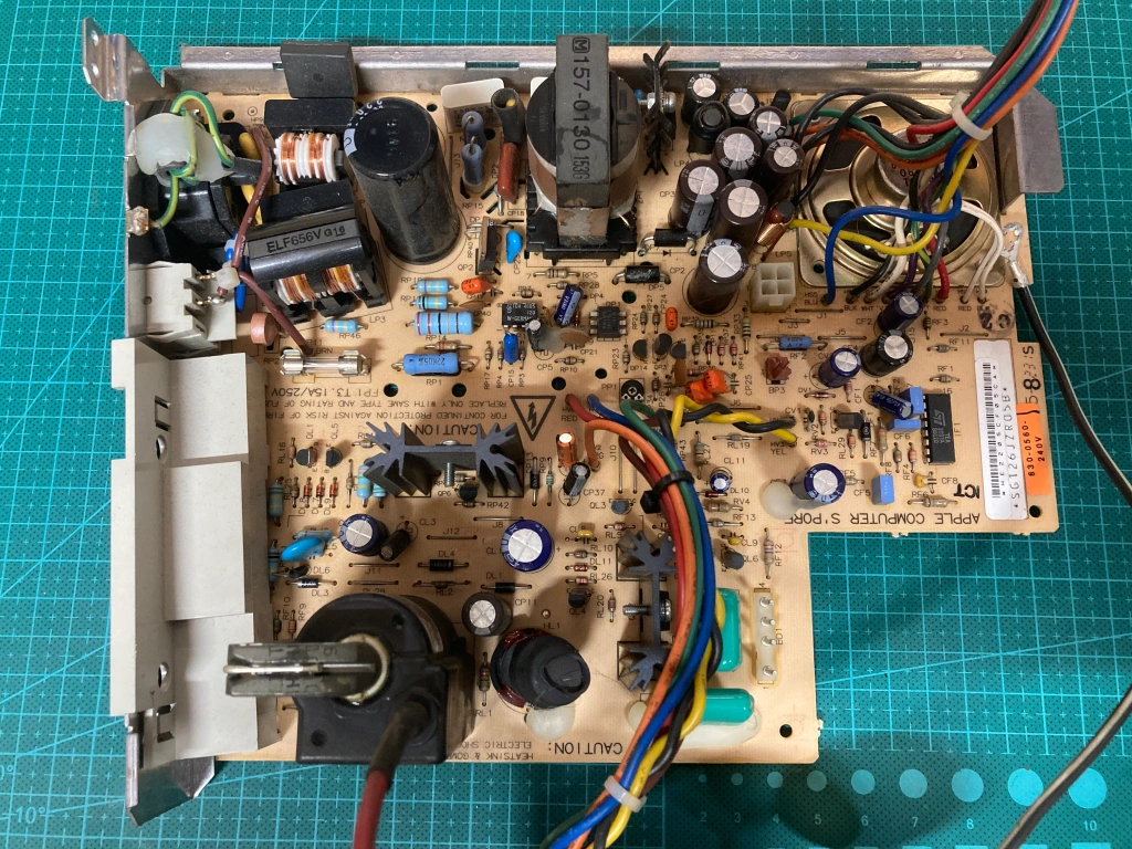
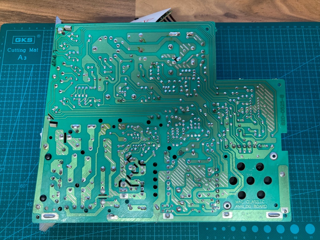
The analogue board is common between the Classic I and Classic II – these had all started to leak, and although the one removed from this Classic II was one of the better ones, the underside of the board was still soaked in a smelly, sticky electrolyte.
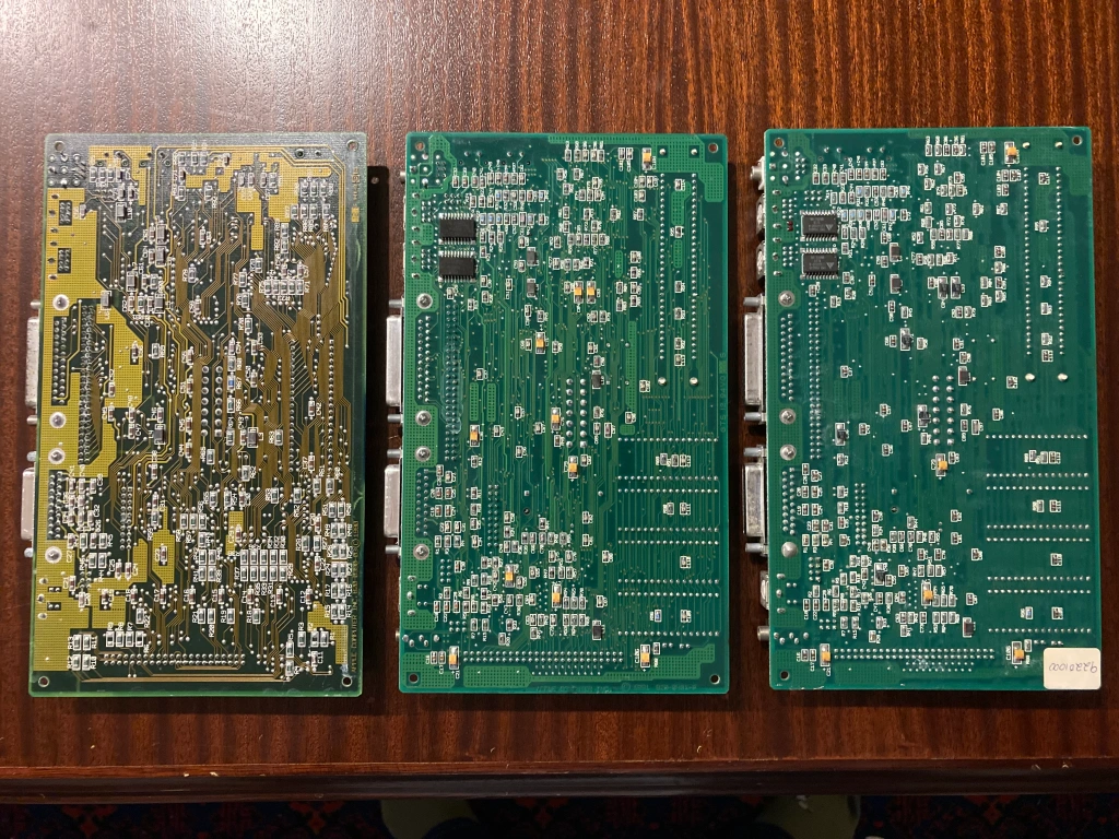
Digital Board Rebuild
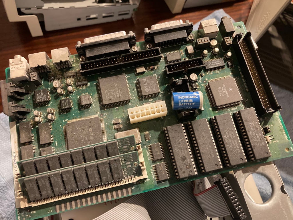
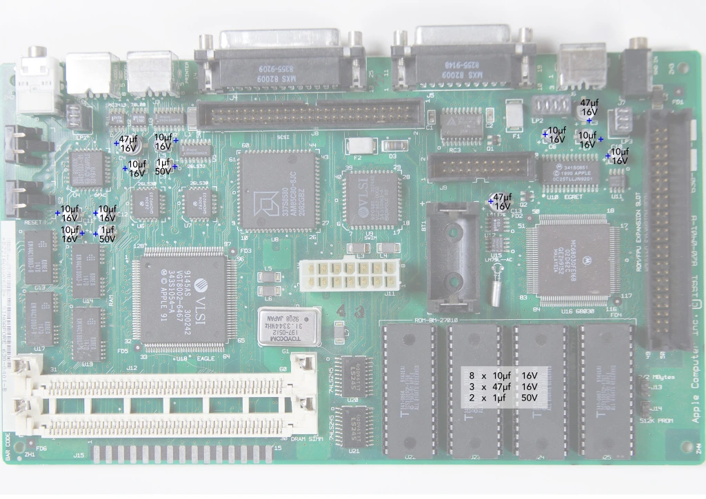
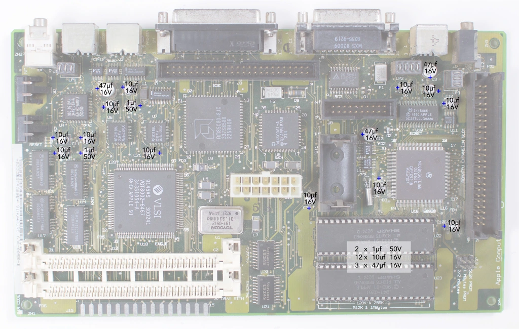
There are two production variants of the Mac Classic II digital board, one with four ROM ICS (rev.A) and one with two larger ROM ICs (rev.B) – the rev.A board has thirteen SMD electrolytic capacitors (2 x 1uF 50V, 8 x 10uF 16V, 3 x 47uF 16V), and the rev.B board has seventeen SMD electrolytic capacitors (2 x 1uF 50V, 12 x 10uF 16V, 3 x 47uF 16V).
The original parts can be removed using a hot air rework station with kapton tape and aluminium foil to protect the surrounding areas, or by carefully twisting them off using needle-nose pliers (this technique may not be suitable if the pads are damaged, as they could delaminate from the board). The pads can then be cleaned up using new leaded solder and either desoldering braid or a desoldering station. Finally, the board should be thoroughly cleaned to remove any leaked electrolyte and leftover flux, using isopropyl alcohol and ESD-safe brushes. I also gave the board a run in my ultrasonic bath.
The new parts can then be fitted. The originals were aluminium electrolytic capacitors with a liquid electrolyte, however its very common for those recapping classic Macintoshes to use tantalum electrolytic capacitors – these use a solid electrolyte, meaning that they will not physically leak. I used 1uF 50V parts, 10uF 16V parts, and 47uF 16V parts from KEMET.
When fitting new electrolytic capacitors, you must take care to ensure that the value, voltage rating, and orientation of the new capacitor are correct – electrolytic capacitors are polarised, so must be installed the correct way around, else they’ll get hot when powered on (and probably explode). The polarity is marked on the case: for aluminium electrolytic capacitors, the negative side is usually shown by a white stripe (for through-hole) or a black bar (for SMD); for tantalum capacitors, the positive side is usually shown by an orange or white bar (for SMD).
You can’t always trust the orientation markings on the PCB silkscreen (if it even has them, not all boards do), as sometimes mistakes were made in the design from the factory (take the PCB layout of the audio circuit on the Commodore CD32, for example), so care must be taken to match the orientation of the new capacitor with the original. Make sure to take lots of “before” pictures for reference.
I also cleaned all of the sockets and ports on the digital board using contact cleaner – I also fitted a replacement PRAM battery, a Saft LS14250 (3.6V 1/2AA).
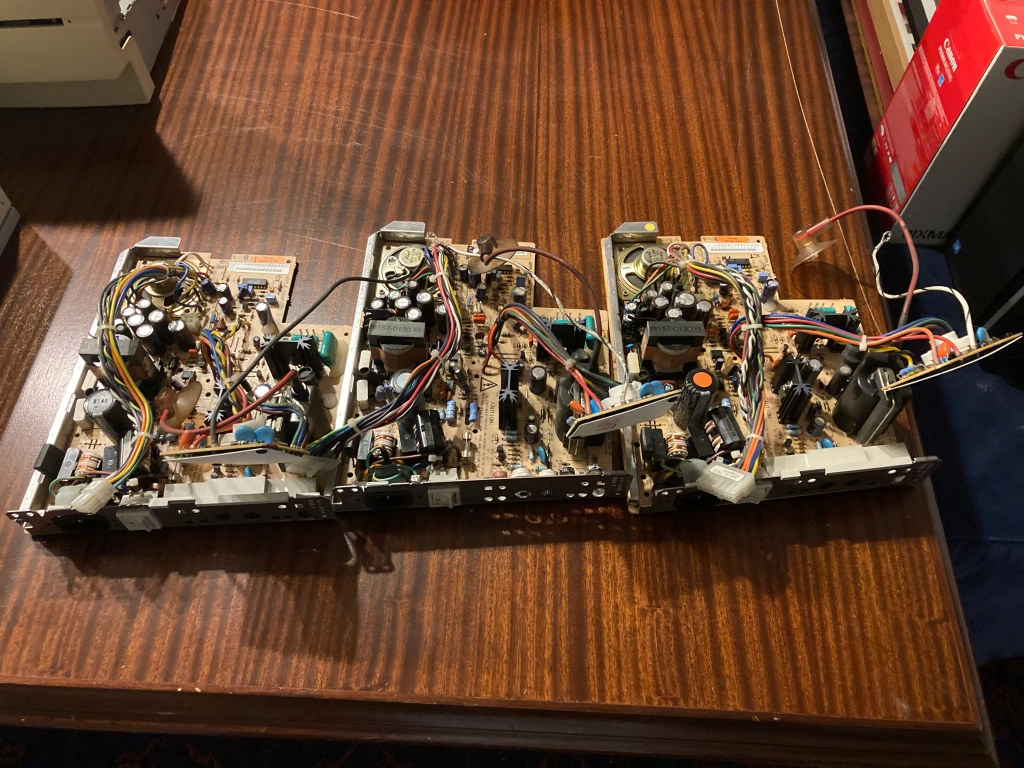
Analogue Board Rebuild
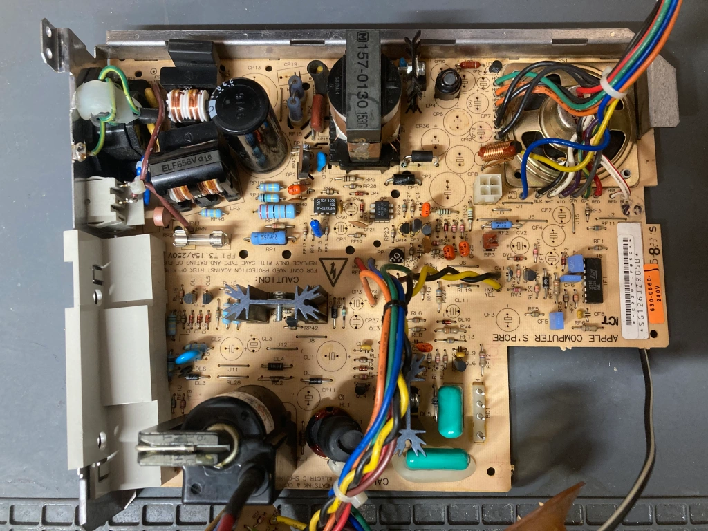
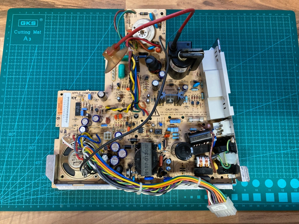
I wanted to rebuild the analogue board for the Mac Classic II, which generates the main power supplies for the digital board as well as the high-voltage and vertical/horizontal deflection for the CRT display – this primarily involved reflowing any bad solder joints, replacing all of the aluminium electrolytic capacitors on the board, and replacing two of the mains filter capacitors (CP18 and CP19) which had cracked.
The insulation on the back of the analogue board is held in place with four plastic clips.
Cracked and cold solder joints are common in equipment of this era, especially on joints which are under physical stress, such as on connectors and under heavy components like the flyback transformer – it’s a good idea to check over the boards looking for bad joints, as these can cause all kinds of weird and intermittent issues. Ideally the original solder should be removed, and replaced with new solder.
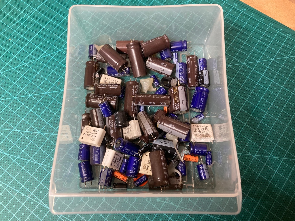
Aluminium electrolytic capacitors are commonly used for filtering, smoothing, and decoupling in both high- and low-voltage electronics. They typically comprise aluminium windings which are coated with a liquid electrolyte, which can dry out over time (negatively affecting the performance of the capacitor, often causing them to fail dead-short), or leak out and cause corrosion to the PCB and surrounding components.
The Mac Classic I and Classic II analogue boards uses through-hole aluminium electrolytic capacitors – these are typically very reliable, however for whatever reason several of the specific parts used in these boards (Nichicon PL series) commonly leak, and badly.
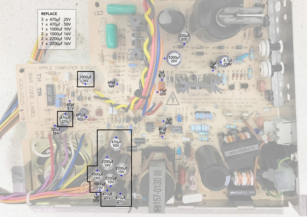
You can probably get away with only replacing the worst offenders (see image above), however all aluminium electrolytic capacitors have a limited service life, so I replaced them all (except for the main bulk capacitor); I also replaced two of the mains filter capacitors (CP18 and CP19), which had cracked
I usually remove each capacitor one-by-one using my desoldering station (a Duratool D00672) and immediately install a replacement, then clean up all the remaining flux residue or heat marks using 99.9% IPA.
However, in the case of Mac Classic II analogue boards, the capacitor leakage is usually so bad that I strip all of the capacitors at the same time, so the board can be more thoroughly cleaned underneath.
When fitting new electrolytic capacitors, you must take care to ensure that the value, voltage rating, and orientation of the new capacitor are correct – electrolytic capacitors are polarised, so must be installed the correct way around, else they’ll get hot when powered on (and probably explode). The polarity is marked on the case: for aluminium electrolytic capacitors, the negative side is usually shown by a white stripe (for through-hole) or a black bar (for SMD); for tantalum capacitors, the positive side is usually shown by an orange or white bar (for SMD).
You can’t always trust the orientation markings on the PCB silkscreen (if it even has them, not all boards do), as sometimes mistakes were made in the design from the factory (take the PCB layout of the audio circuit on the Commodore CD32, for example), so care must be taken to match the orientation of the new capacitor with the original. Make sure to take lots of “before” pictures for reference.
When substituting electrolytic capacitors, the capacitance needs to be the same, and the voltage rating can be the same or higher (within reason) – when you’re going through all this effort to recap something, be sure to use high-quality replacements.
I couldn’t find any commercially available capacitor packs for the international version of the Mac Classic II analogue board, so I just made up my own by noting the specifications of all of the electrolytic capacitors on the board, and ordering a set of high-quality known-brand (i.e. Panasonic, Nichicon, etc) 105C-rated parts.
This was a total of:
- 4 x 1uF 50V radial
- 1 x 4.7uF 250V radial
- 1 x 10uF 25V radial
- 3 x 47uF 25V radial
- 2 x 220uF 50V radial
- 5 x 470uF 50V radial
- 4 x 1000uF 25V radial
- 3 x 2200uF 16V radial
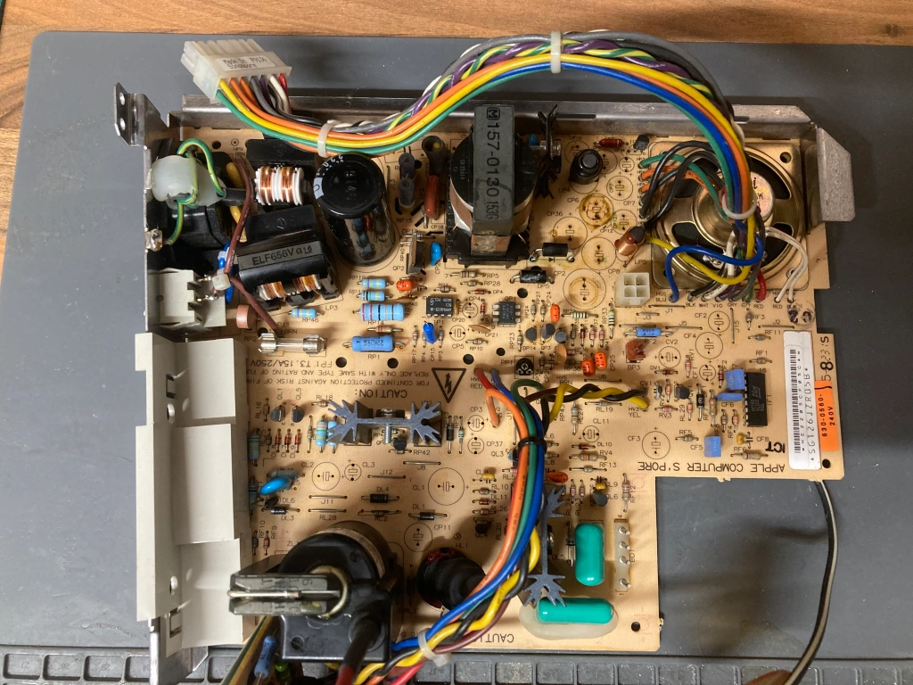
I also replaced the two mains filter capacitors with suitable 10nF safety capacitors.
If you lose any of the plastic pop-rivets, you can still buy R3055 parts.
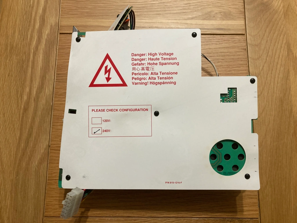
I also made sure that the low-voltage side of the analogue board was set up correctly.
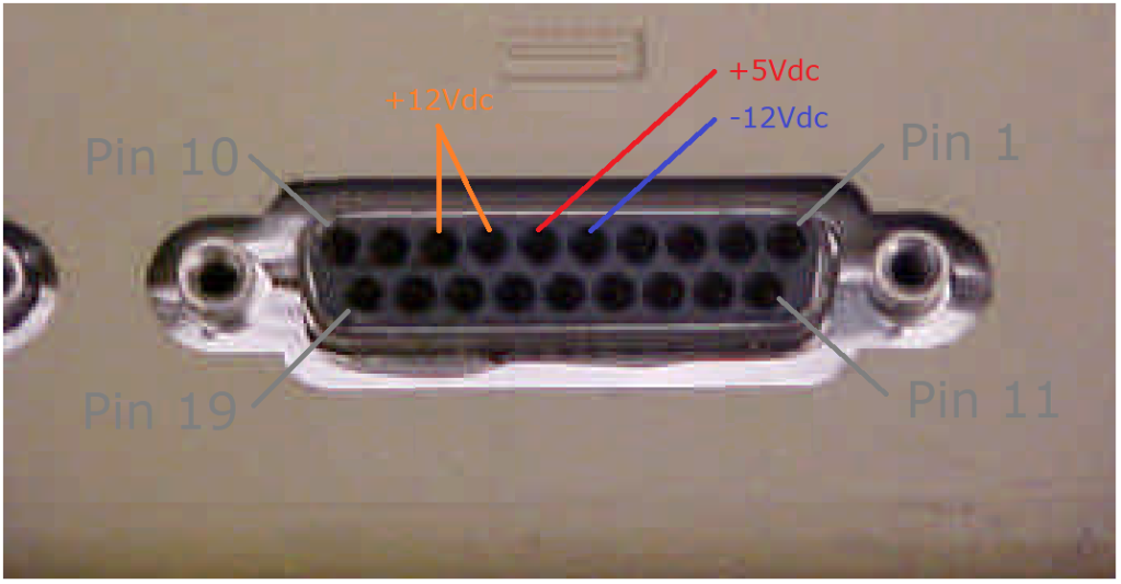
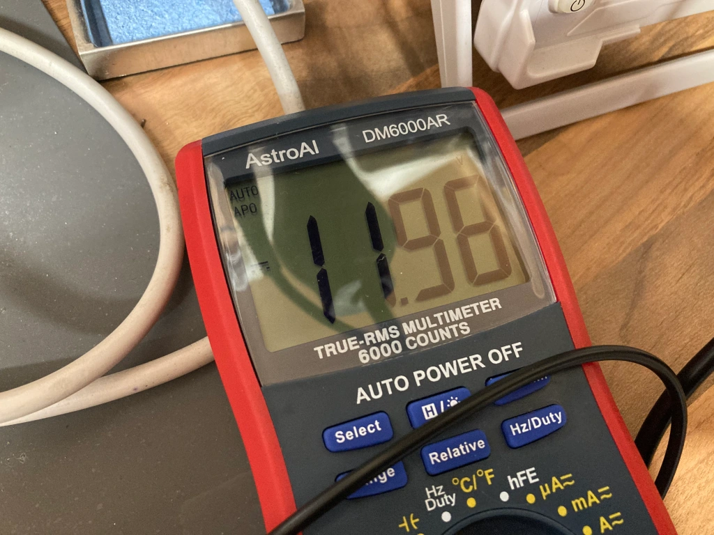
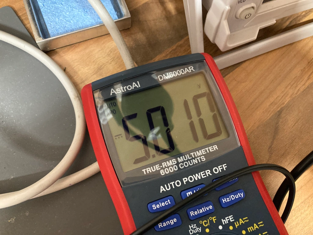
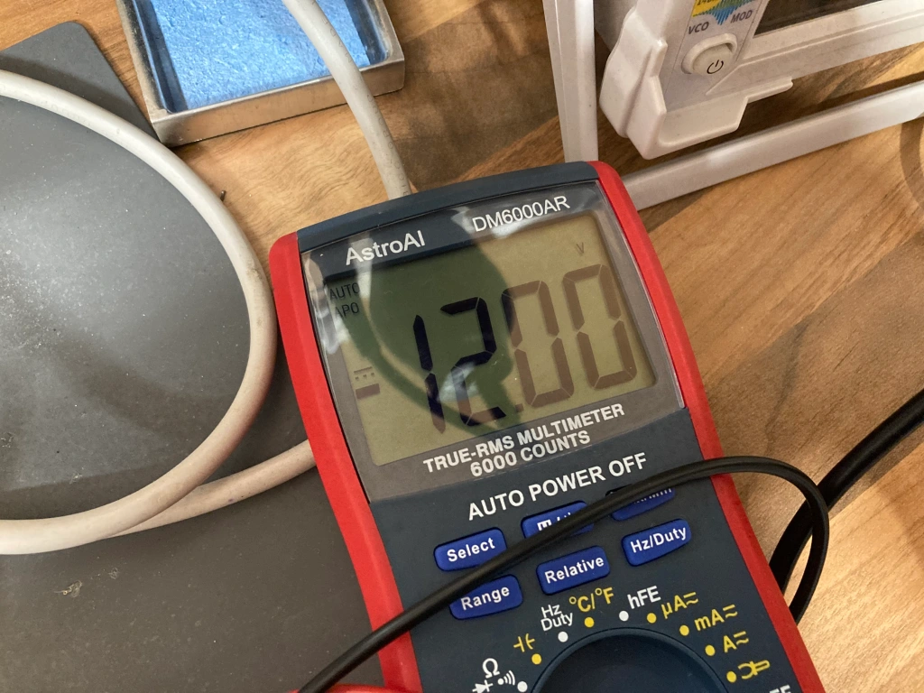
The analogue board supplies three low-voltage power rails which are used by the digital board: +5Vdc, +12Vdc, and -12Vdc. +5Vdc and -12Vdc are derived from the +12Vdc supply, so there is only a single common adjustment.
Measuring these three supplies is easiest to do via the external floppy drive connector on the digital board – this has -12Vdc on pin 5, +5Vdc on pin 6, and +12Vdc on pins 7 and 8.
I measured these with my multimeter, used the rotary potentiometer PP1 to adjust the +12Vdc rail, whilst keeping an eye on the 5Vdc rail, to bring these as close as possible.
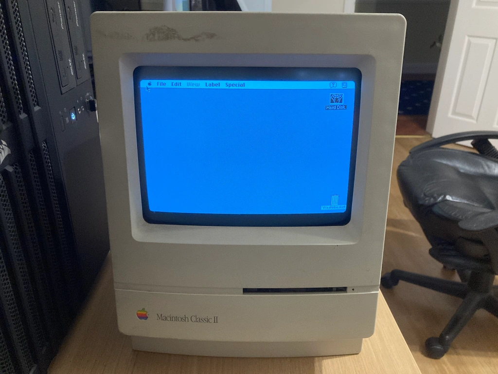
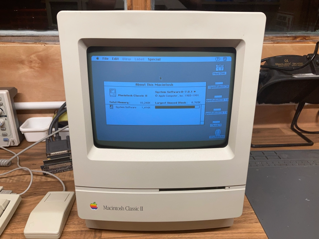
With this work complete, the Mac Classic II seemed to boot reliably onto the version of System 7 that was already installed on the internal HDD.
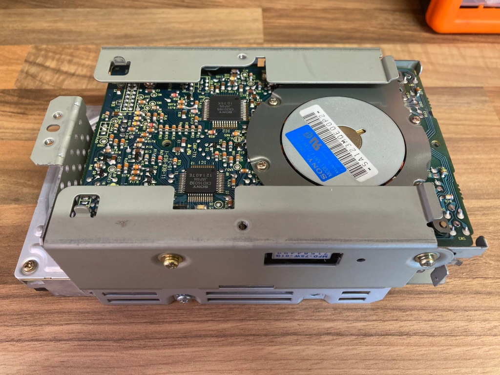
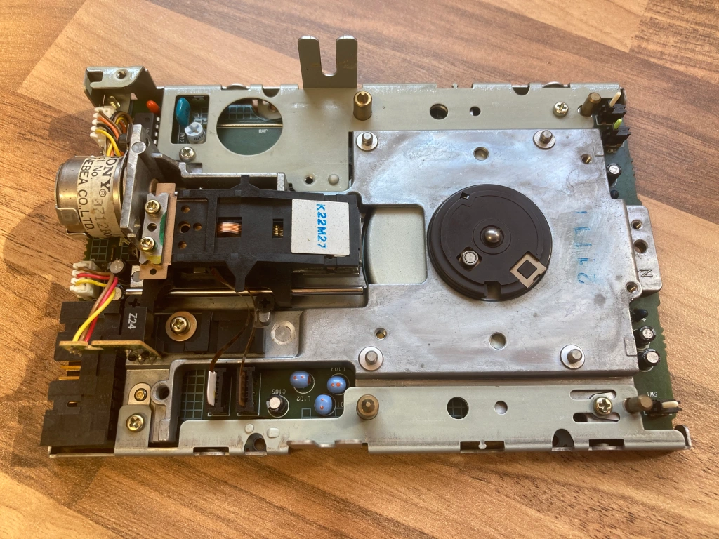
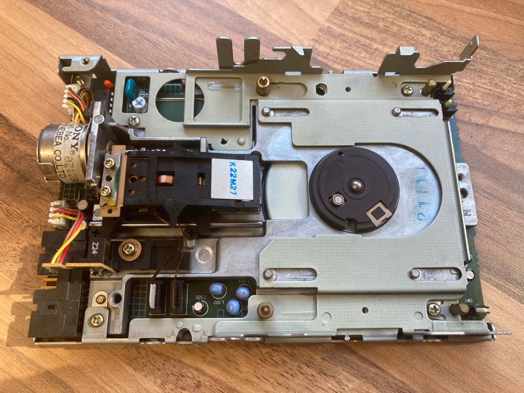
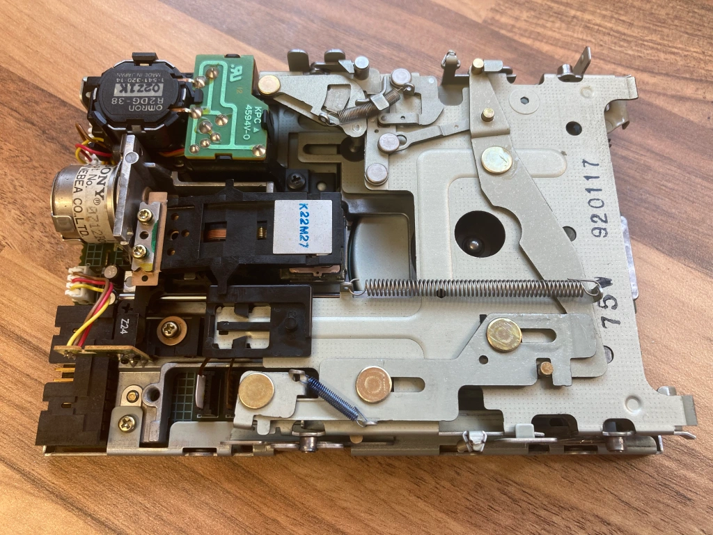
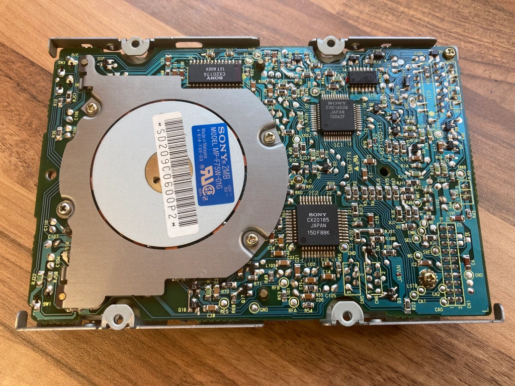
Disk Drive Servicing
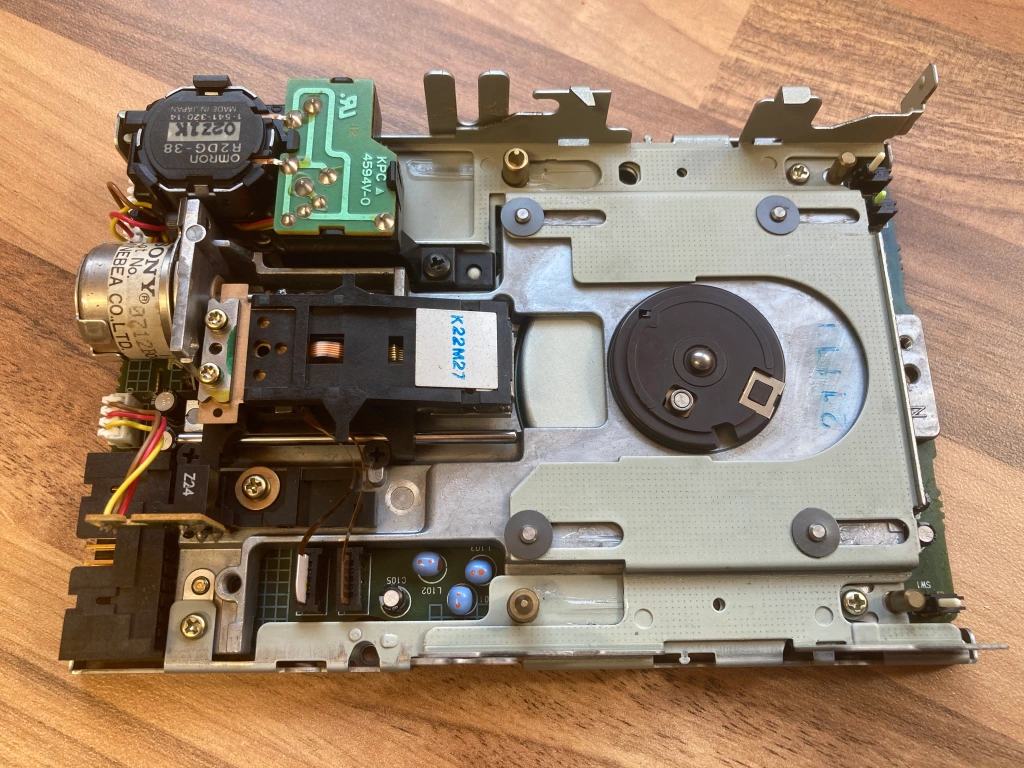
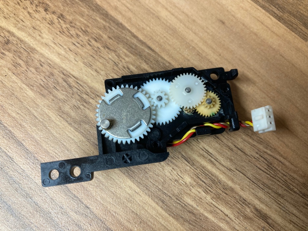
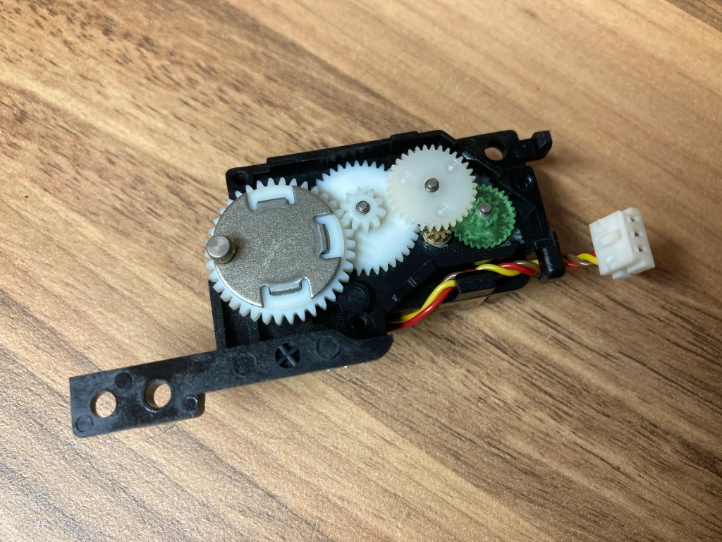
The 3.5″ 1.4MB floppy disk drive in the Mac Classic I and Classic II usually requires a service due to its old age – the eject mechanism gets gummed up and doesn’t work properly any more, the eject motor gear has a habit of cracking and failing, the drive internals get dusty, and the read/write heads will probably need a good clean.
The FDD needs to be removed for servicing – the drive caddy is held into place on the chassis with four cross-head screws, and the drive itself is held into the caddy with another four cross-head screws.
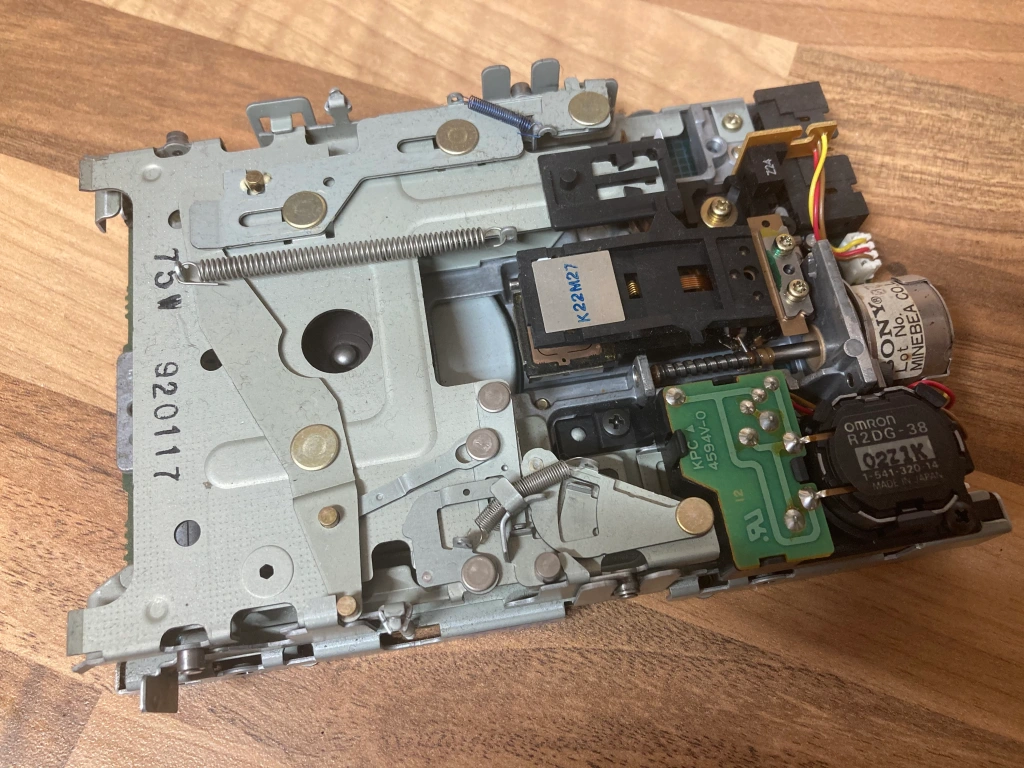
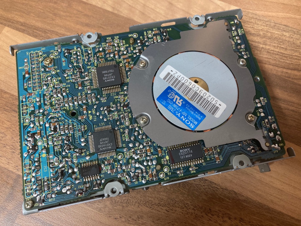
I won’t go into detail about the drive service procedure, as Adrian Black has an excellent video on the subject – it basically involves dismantling the drive, cleaning the old grease and any grime, adding new lubricant to the stepper rails and screw, cleaning the read/write heads with IPA, and cleaning the microswitches with contact cleaner.
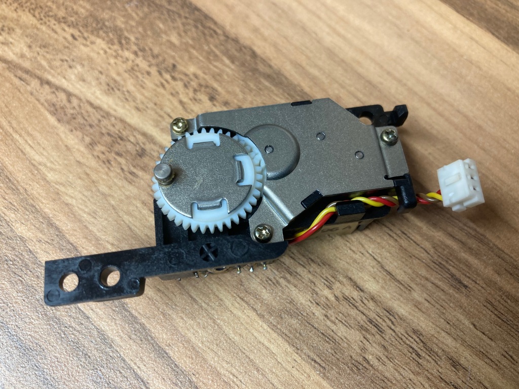
I also decided to replace the original brittle eject gear inside the eject mechanism, using a suitable 3D-printed replacement which will last much longer.
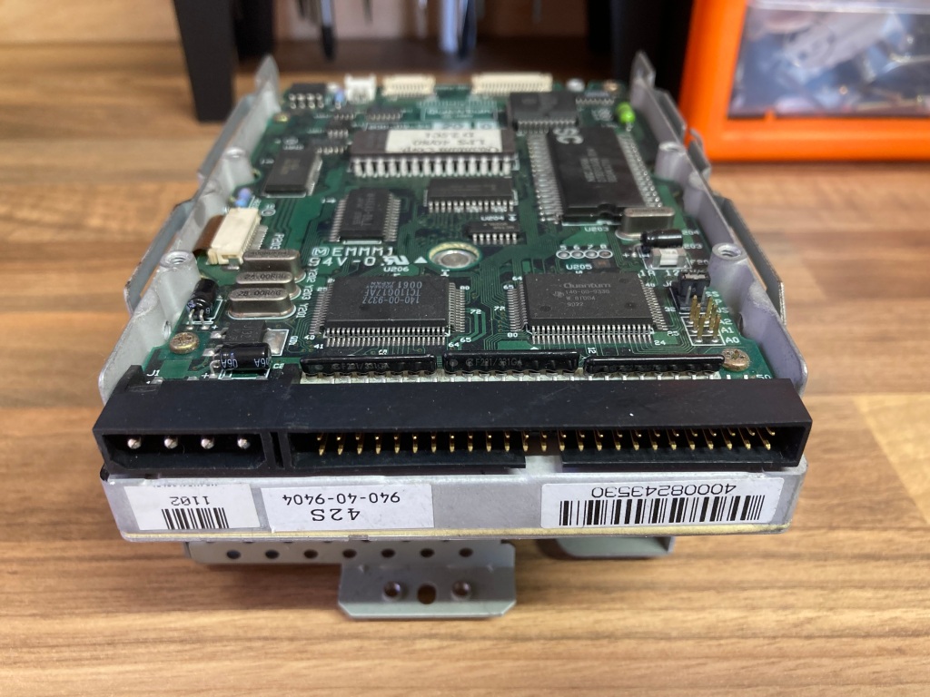
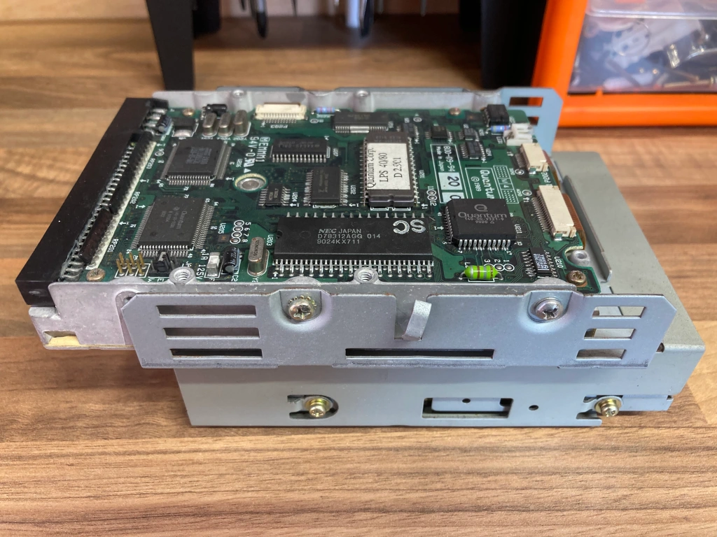
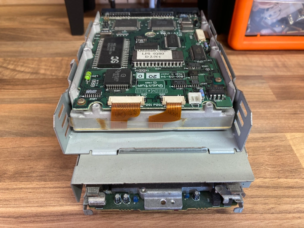
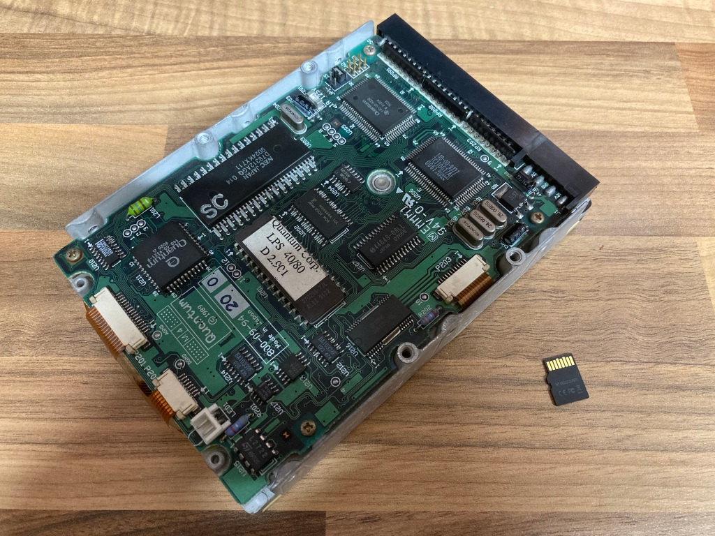
HDD Upgrade
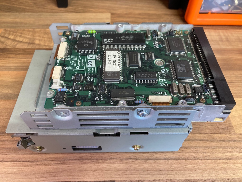
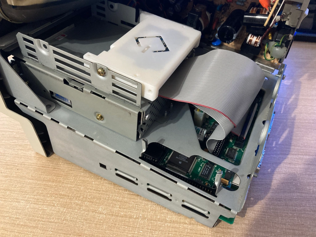
The Mac Classic II still had what appeared to be the factory HDD fitted, a 3.5″ 40MB Quantum SCSI HDD – this was working, and had System 7 installed. However, these old mechanical drives are starting to die out – they’re unreliable, noisy, slow, and difficult to interface with, and I prefer to swap them for a solid-state alternative (i.e. an SD card) where possible.
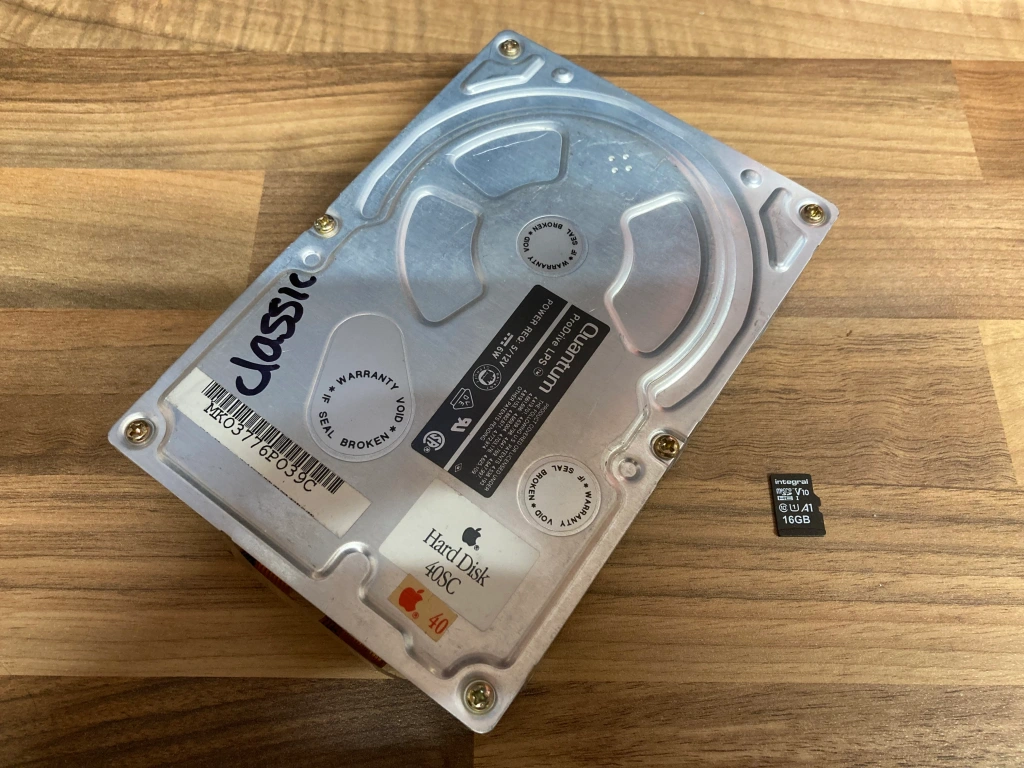
For the SD card adapter, I decided to go with a BlueSCSI, for various reasons: they’re easy to find, cheap to build/buy, are easy to set up and use, and because I’d already made some for my Mac Plus, and had spare parts in stock. Before fitting it, I used it to take a backup of the contents of the original HDD in this machine.
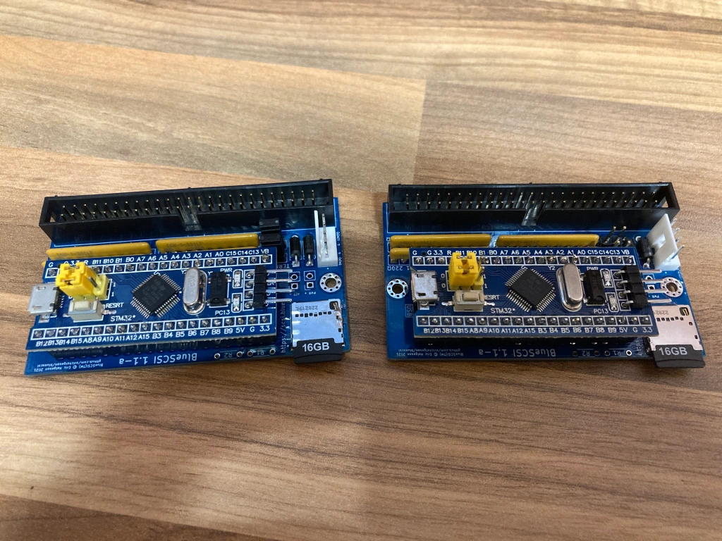
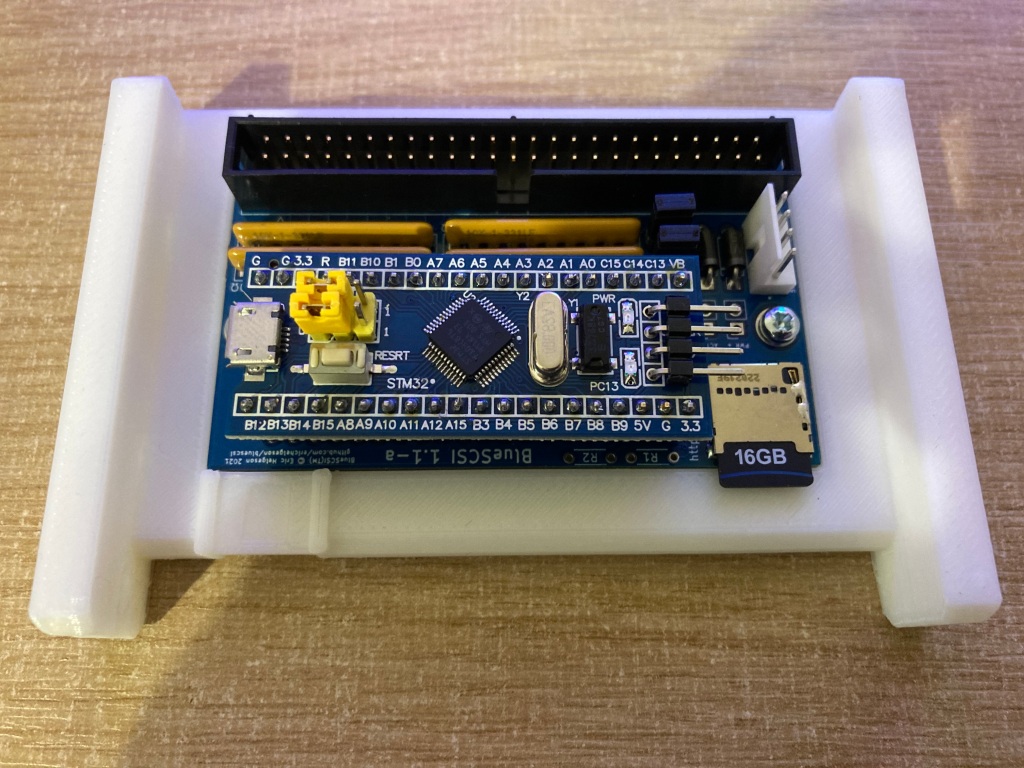
The BlueSCSI fits into a 3D-printed 3.5″ drive adapter– this is available to buy from the creator, which I didn’t realise at the time, so I used the open-source design files and had several parts made by PCBWay, and bought some of the appropriate PCB mounting screws (M2.5 x 5mm).
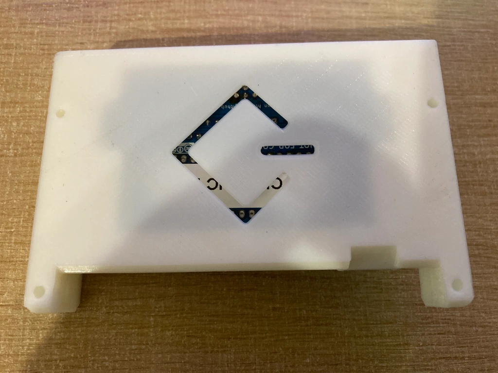
The 3.5″ adapter can then be installed into the drive caddy using the original screws. Because the factory SCSI cable in the Mac Classic is quite short, I had to mount it upside-down and towards the back of the caddy.
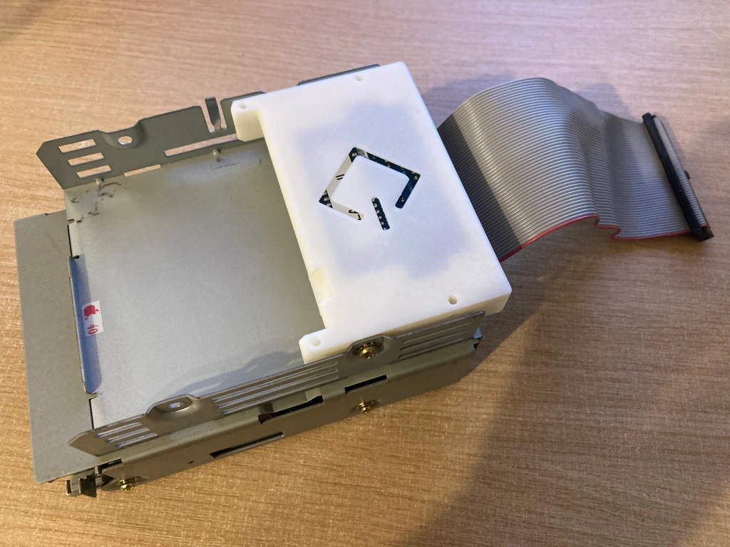
The drive caddy can then be fitted back into the computer case, and connected to the SCSI cable – a power adapter cable is not required as power is provided over the SCSI bus, and I typically remove the original HDD power cable too as it is no longer necessary. The BlueSCSI has pin headers for both power and drive activity LEDs, but I didn’t connect anything to these.
Reassembly & Testing
The reassembly of the computer is the opposite procedure to its disassembly.
After all of this work, I tested the Mac Classic II with the SD card adapter installed, and it now booted correctly into the operating system loaded onto the SD card.
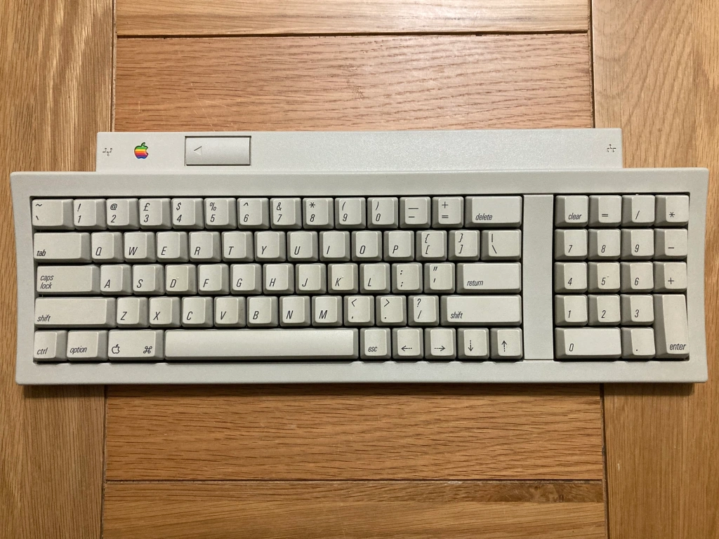
- All keys register correctly.
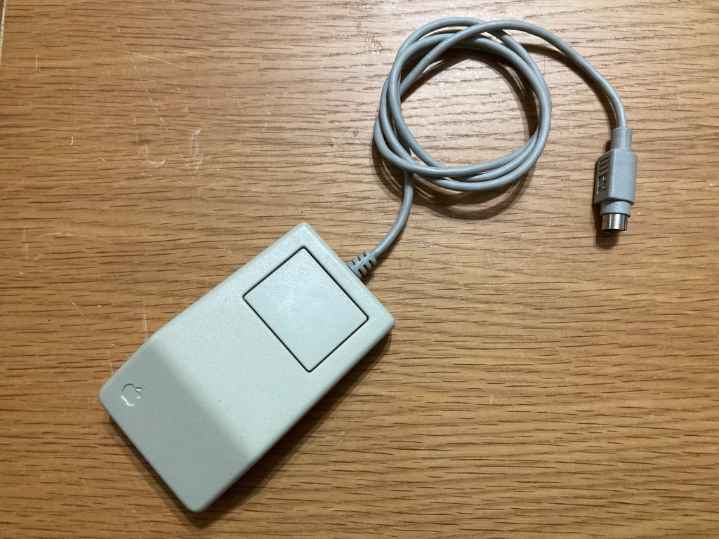
- All mouse inputs work OK.
- Internal FDD works OK.
- Internal HDD works OK.
- External SCSI interface works OK.
- Monochrome video on internal CRT works OK.
- Internal speaker works OK.
- Audio output works OK.
- 10MB RAM registers OK.
- NMI and reset buttons work OK.

you’re shaming me into action 🙂 I did however discover I had a superdrive in an LCII that I had picked up for 10.00 just because it was there, so thanks to your last post that has happened.
LikeLiked by 1 person
That’s great news, well done 😊
LikeLike