FM Slope Detector Demodulator:
FM slope detection is a concept that can used be recover the modulation from an FM signal, but it is not widely used.
There are far more efficient methods that can be used for FM detection / demodulation.
However as a concept it is useful to understand.
FM slope detection basics:
The very simplest form of FM demodulation is known as slope detection or demodulation. It consists of a tuned circuit that is tuned to a frequency slightly offset from the carrier of the signal.
As the frequency of the signals varies up and down in frequency according to its modulation, so the signal moves up and down the slope of the tuned circuit. This causes the amplitude of the signal to vary in line with the frequency variations. In fact at this point the signal has both frequency and amplitude variations.
It can be seen from the diagram that changes in the slope of the filter, reflect into the linearity of the demodulation process. The linearity is very dependent not only on the filter slope as it falls away, but also the tuning of the receiver – it is necessary to tune the receiver off frequency and to a pint where the filter characteristic is relatively linear.
The final stage in the process is to demodulate the amplitude modulation and this can be achieved using a simple diode circuit. One of the most obvious disadvantages of this simple approach is the fact that both amplitude and frequency variations in the incoming signal appear at the output. However the amplitude variations can be removed by placing a limiter before the detector.
A variety of FM slope detector circuits may be used, but the one below shows one possible circuit with the applicable waveforms. The input signal is a frequency modulated signal. It is applied to the tuned transformer (T1, C1, C2 combination) which is offset from the centre carrier frequency. This converts the incoming signal from just FM to one that has amplitude modulation superimposed upon the signal.
This amplitude signal is applied to a simple diode detector circuit, D1. Here the diode provides the rectification, while C3 removes any unwanted high frequency components, and R1 provides a load.
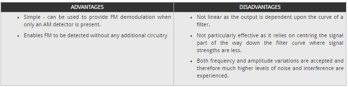
FM slope detection advantages & disadvantages:
FM slope detection is not widely used, and yet it has some limited applications. Knowing the advantages and disadvantages enables the technique to be used where applicable.