Download presentation
Presentation is loading. Please wait.

1
By Velar H. Elias Measurement

2
Introduction CHAPTER ONE

3
INTRODUCTION Measurement: measurement means, to monitor a process or a operation and using an instrument, express the parameter, quantity or a variable in terms of meaningful numbers. Measurement of a given parameter or quantity is the act or result of a quantitative comparison between a predefined standard and an unknown quantity to be measured.

4
Evolution of Instruments I
Mechanical Electrical Electronic Instruments Mechanical: these instruments are very reliable for static and stable conditions. But their disadvantage is that they are unable to respond rapidly to measurements of dynamic and transient conditions.

5
Evolution of Instruments II
Electrical: it is faster than mechanical, indicating the output are rapid than mechanical methods. But it depends on the mechanical movement of the meters. The response is between 0.5 to 24 seconds. Electronic: it is more reliable then other system. It uses semiconductor devices and weak signal can also be detected.

6
Advantages of Electronic Measurement
Most of the quantities can be converted by transducers into the electrical or electronic signals. Electronic signals can be amplified, filtered, multiplexed, sampled and measured. Measured signals can be transmitted over long distance through cables or radio links, without any loss of information. Many measurements can be done simultaneously or in rapid succession. Electronic circuits can measure the events of very short duration. Higher sensitivity, low power consumption and a higher degree of reliability are the important features.

7
Performance Characteristics
Static Characteristics: the set of criteria defined for the instruments, which are used to measure the quantities which are slowly varying with time or mostly constant, i.e., do not vary with time is called static characteristics. Dynamic Characteristics: when the quantity under measurement changes rapidly with time, it is necessary to study the dynamic relations existing between input and output which is expressed as differential equations.

8
CALIBRATION calibration is the process of making an adjustment or making a scale so that the reading on an instrument agree with the accepted and certified standard. Calibration is a comparison between a known measurement (the standard) and the measurement using your instrument. Typically, the accuracy of the standard should be ten times the accuracy of the measuring device being tested. However, accuracy ratio of 3:1 is acceptable by most standards organizations. In practice, calibration also includes repair of the device if it is out of calibration.
 and the measurement using your instrument. Typically, the accuracy of the standard should be ten times the accuracy of the measuring device being tested. However, accuracy ratio of 3:1 is acceptable by most standards organizations. In practice, calibration also includes repair of the device if it is out of calibration.")
9
CALIBRATION Calibration of your measuring instruments has two objectives: It checks the accuracy of the instrument And it determines the traceability of the measurement. Calibration improves the accuracy of the measuring device. Accurate measuring devices improve product quality. When should you calibrate your measuring device? According to recommendation of the manufacturer. After any mechanical or electrical shock. Periodically (Daily, monthly, before use)
")
10
Definitions Instrument: a device for determining the value or magnitude of a quantity or variable. Accuracy: closeness with which an instrument reading approaches the true value of the variable being measured. Precision: a measure of the reproducibility of the measurement i.e., given a fixed value of a variable, precision is a measure of the degree to which successive measurements differ from one another.

11
Definitions Sensitivity: the ratio of output signal or response of the instrument to a change of input or measured variable. Resolution: the smallest change in measured value to which the instrument will response. Error: deviation from the true value of the measured variable. Several techniques may be used to minimize the effect of error. the algebraic difference between the indicated value and the true value of the quantity to be measured is called an ERROR

12
Precision and accuracy comparison
Accuracy refers to the degree of closeness or conformity to the true value at the quantity under measurement. Precision refers to the degree of agreement within a group of measurements or instruments. In critical work, good practice dictates that the observer make an independent set of measurements, using different instruments or different measurement techniques, not subject to the same systematic errors. He must also make sure that the instruments function properly and are calibrated against a known standard, and that no outside influence affects the accuracy of his measurements.

13
Precision and accuracy comparison

14
Sources of Errors Faulty design of instrument
Insufficient knowledge of quantity and design conditions Improper maintenance of the instrument. Sudden change in the parameter to the measured. Unskilled operator Effects of environmental conditions.

15
Errors A study of errors is a first step in finding way to reduce them. Errors types: Gross errors: Largely human errors, among them misreading of instruments incorrect adjustment and improper application of instruments, and computational mistakes. Systematic errors: Short coming of the instruments, such as defective or wrong parts, and effective of environment on the equipment or the user. (Instrument Error) Random errors: these errors are due to unknown causes and occur even when all systematic errors have been accounted for.
 Random errors: these errors are due to unknown causes and occur even when all systematic errors have been accounted for.")
16
Gross Error: (Personal Errors)
Occurs due to carelessness of human while reading, recording and calculating results. Due to incorrect adjustments of instruments. To eliminate error Take care while reading, recording and calculating results. Take 3 or more reading with 3 or more persons.

17
Systematic Error Types Instrumental error Environmental error
Observational error

18
Systematic-Instrumental Errors
Defined as shortcoming of the instrument, and can be avoided by: Selecting a suitable instrument for the particular measurement application Applying correction factors after determining the amount of instrument error Calibrating the instrument against the standard

19
Systematic-Environmental errors
Due to external conditions affection the measurement, environmental errors are due to conditions external to the measuring device, including conditions in the area surrounding the instrument, such as the effect of change in temperature, humidity, barometric pressure, or of the magnetic or electrostatic fields Systematic errors can also be subdivided into static or dynamic errors.

20
Systematic-Environmental errors
To eliminate the error: Proper correction factors given by the manufacturer. Make arrangements to keep surrounding constant . Sealing the components to avoid dust, humidity Providing magnetic or electrostatic shields

21
Observational errors Errors made by observes
Ex: parallax error while reading a meter, wrong scale selection To eliminate the error Use instruments with mirrors Knife edged pointers

22
Random errors In well designed experiments, few random errors usually occur, but they become important in high accuracy work. The only way to offset these errors is by increasing the number of readings and using statistical means to obtain the best approximation of the true value of the quantity under measurement They cannot be corrected by any method.

23
CHAPTER TWO UNITS, STANDARDS and INSTRUMENTS

24
UNITS It is necessary to specify type and magnitude for the reading. Where unit represents the type of the physical quantity and reading on the instrument represents its magnitude. Different system of units are M.K.S C.G.S S.I (System International units)
")
25
System International Units (SI)
Quantity Units Symbol Length Meter M Mass Kilogram Kg Time Second S Electrical current Ampere A Thermal temperature Kelvin K Luminous intensity Candela cd Amount of substance Mole mol

26
Table of units Name Symbol Equivalent Yotta Y 10^24 Zetta Z 10^21 Exa
10^18 Peta P 10^15 Tera T 10^12 Giga G 10^9 Mega M 10^6 Kilo K 10^3 Hecto h 10^2 Deca da 10 Deci d 10^-1

27
Table of Units Name Symbol Equivalent Centi c 10^-2 Mili m 10^-3 Micro
μ 10^-6 Nano n 10^-9 Pico p 10^-12 Femto f 10^-15 Atto a 10^-18 Zepto z 10^-21 Yocto y 10^-24

28
UNITS Units categories Fundamental Units: Fundamental Units
Supplementary Units Derived Units Fundamental Units: Units which are independently chosen and not dependent on any other units are called fundamental units of base units.

29
UNITS Primary fundamental units Auxiliary fundamental units Length
Thermal Mass Electrical Time Illumination Amount of substance

30
UNITS Supplementary Units: Derived Units:
Radian for the plane angle(θ,φ) Plane angle subtended by an arc of a circle equal in length to the radius of the circle. Derived Units: These units are derived from fundamental and supplementary units. Ex: velocity (m/s), acceleration (m/s2), force (N)
 Plane angle subtended by an arc of a circle equal in length to the radius of the circle. Derived Units: These units are derived from fundamental and supplementary units. Ex: velocity (m/s), acceleration (m/s2), force (N)")
31
UNITS Table of some of the derived units Quantity Units Symbol
Electrical capacitance Farad (1C/1V) F Electrical charge Coulomb (1A.1Sec) C Electric conductance Siemens (1/ohm) S Electric potential Volt (1J/1C) V Electric resistance Ohm (V/A) Ω Energy Joule (1N.1meter) J Force Newton (1Kg*meter)/sec^2 N Frequency Hertz (1/sec) Hz Magnetic flux Weber (Kg*meter^2)/(A*sec^2) = (1V*1sec) Wb Magnetic flux density Tesla (V*sec/meter^2) T Plane angle Radian (length of a corresponding arc of a unit circle) rad Power Watt (1J/1Sec) (V^2 / Ω) = (A^2 * Ω) W
 F. Electrical charge. Coulomb (1A.1Sec) C. Electric conductance. Siemens (1/ohm) S. Electric potential. Volt (1J/1C) V. Electric resistance. Ohm (V/A) Ω. Energy. Joule (1N.1meter) J. Force. Newton (1Kg*meter)/sec^2. N. Frequency. Hertz (1/sec) Hz. Magnetic flux. Weber (Kg*meter^2)/(A*sec^2) = (1V*1sec) Wb. Magnetic flux density. Tesla (V*sec/meter^2) T. Plane angle. Radian (length of a corresponding arc of a unit circle) rad. Power. Watt (1J/1Sec) (V^2 / Ω) = (A^2 * Ω) W.")
32
Units Radian =360/2π degree=180/π degree
1 Coulomb = 6.28 *10^18 Electrons Light speed = m/sec What is mean by Unitless value? Conversion of UNITS

33
English to SI unit conversion
English Units Symbol Metric equivalent Length foot 1 inch ft in 30.48 cm 25.4 mm Mass pound Lb kg Density lb/ft^3 kg/m^3 Velocity ft/sec^2 m/sec^2 Force poundal pdl N Work, energy 1 ft*pdl J Power horse-power hp W Temperature degree Fº Fahrenheit 5(t-32)/9 Cº
/9 Cº.")
34
STANDARDS Type of standards
a standard of measurement is a physical representation of a unit of measurement. a unit is realized by reference to an arbitrary material standard or to natural phenomena including physical and atomic constant. Type of standards International standards Primary standards Secondary standards Working standards Just as there are fundamental and derived units of measurement, we find different types of standards of measurement, classified by their function and application in the following categories.

35
International Standards
These standards are maintained at the (IBS) international bureau of weights and measures and are periodically evaluated and checked by absolute measurements. These standards are not available for ordinary users for calibration. For accuracy they are replaced by absolute units which are more accurate than international standards.
 international bureau of weights and measures and are periodically evaluated and checked by absolute measurements. These standards are not available for ordinary users for calibration. For accuracy they are replaced by absolute units which are more accurate than international standards.")
36
Primary Standards They are maintained at national standard laboratories in different countries (NBS). These standards represents fundamental units as well as electrical and mechanical derived calibrated by absolute measurements at each national laboratories. Used for calibration and verification of secondary standards.

37
Secondary Standards Since primary standards are not available for outside users, various industries need some reference. They are used by measurement and calibration laboratories and are maintained by the particular industry to which they belong. Each industry has its own standards

38
Working Standards These are the basic tools of a measurement laboratory. Use to check and calibration for accuracy and performance or to perform comparison measurements in industrial applications. Ex: resistor industry maintains a standard resistor for checking the values of manufactured resistors

39
IEEE Standards Institute of Electrical and Electronic Engineering standards are checking of secondary standards. Used for testing and evaluating of electronic systems and components. The most important standards is (IEEE 488) digital interface for programmable instrumentation for test and other equipment. IEEE classification (word file)
 digital interface for programmable instrumentation for test and other equipment. IEEE classification (word file)")
40
Analog and Digital Instruments
An analogue instrument are the instrument that use analogue signal to display the magnitude of quantity under measurement. An analogue instrument gives an output that varies continuously as the quantity being measured changes. The output can have an infinite number of values within the range that the instrument is designed to measure.

41
Analog and Digital Instruments
The digital instrument use digital signal to indicate the results of measurement in digital form. A digital instrument has an output that varies in discrete steps and so can only have a finite number of values. like binary signal which take only two levels zero and one.

42
Analog to Digital Converter ADC
Analogue instruments must be interfaced to the microcomputer by an analogue-to-digital (A/D) converter, which converts the analogue output signal from the instrument into an equivalent digital quantity that can be read into the computer. This conversion has several disadvantages. Firstly, the A/D converter adds a significant cost to the system. Secondly, a finite time is involved in the process of converting an analogue signal to a digital quantity, and this time can be critical in the control of fast processes where the accuracy of control depends on the speed of the controlling computer.
 converter, which converts the analogue output signal from the instrument into an equivalent digital quantity that can be read into the computer. This conversion has several disadvantages. Firstly, the A/D converter adds a significant cost to the system. Secondly, a finite time is involved in the process of converting an analogue signal to a digital quantity, and this time can be critical in the control of fast processes where the accuracy of control depends on the speed of the controlling computer.")
43
Electromechanical Instruments vs Digital measuring Instruments
The electromechanical indicating instruments, cheap manually balanced bridge instruments or induction type watt-hour meters are still present everywhere. There are several advantages of traditional electromechanical instruments: simplicity, reliability, low price. The most important advantage is that the majority of such instruments can work without any additional power supply.

44
Electromechanical Instruments vs Digital measuring Instruments
Drawbacks of electromechanical analogue instruments: they do not provide electrical output signal, thus there is a need for operator’s activity during the measurement (at least for the reading of an indicated value). instruments generally use moving mechanical parts, which are sensitive to shocks, aging or wearing out.
. instruments generally use moving mechanical parts, which are sensitive to shocks, aging or wearing out.")
45
Electromechanical Instruments vs Digital measuring Instruments
Moreover without understanding of the principles of old analogue measuring methods it can be difficult to understand usually more complicated digital instruments which often use traditional principles of operation.

46
Active and Passive Instruments
Active Instruments – the quantity being measured simply modulates (adapts to) the magnitude of some external power source. Passive Instruments – the instrument output is entirely produced by the quantity being measured Difference between active & passive instruments is the level of measurement resolution that can be obtained.
 the magnitude of some external power source. Passive Instruments. – the instrument output is entirely produced by the quantity being measured. Difference between active & passive instruments is the level of measurement resolution that can be obtained.")
47
Active and Passive Instruments
1. Active Instruments- e.g. Float-type petrol tank level indicator

48
Active and Passive Instruments
1. Active Instruments- The change in petrol level moves a potentiometer arm, and the output signal consists of a proportion of the external voltage source applied across the two ends of the potentiometer. The energy in the output signal comes from the external power source: the primary transducer float system is merely modulating the value of the voltage from this external power source.

49
Active and Passive Instruments
2. Passive Instruments- e.g. Pressure-measuring device

50
Active and Passive Instruments
The pressure of the fluid is translated into a movement of a pointer against scale. The energy expanded in moving the pointer is derived entirely from the change in pressure measured: there are no other energy inputs to the system.

51
Active and Passive Instruments
Another different is in resolution: Passive instrument: Whilst it is possible to increase measurement resolution by making the pointer longer, such that the pointer tip moves through a longer arc, the scope for such improvement is clearly restricted by the practical limit of how long the pointer can conveniently be. Active instrument, however, adjustment of the magnitude of the external energy input allows much greater control over measurement resolution.

52
Active and Passive Instruments
In terms of cost, passive instruments are normally of a more simple construction than active ones and are therefore cheaper to manufacture. Therefore, choice between active and passive instruments for a particular application involves carefully balancing the measurement resolution requirements against cost.

53
Measuring Instruments
Classified measuring instruments in to two groups: Absolute Instruments (Standard instruments) Secondary Instruments
 Secondary Instruments.")
54
Absolute Instruments These instruments gives the magnitude of quantity under measurement in terms of physical constants of the instrument e.g. Tangent Galvanometer. These instruments do not require comparison with any other standard instrument These instruments give the value of the electrical quantity in terms of absolute quantities (or some constants) of the instruments and their deflections. In this type of instruments no calibration or comparison with other instruments is necessary.
 of the instruments and their deflections. In this type of instruments no calibration or comparison with other instruments is necessary.")
55
Absolute Instruments • They are generally not used in laboratories and are seldom used in practice by electricians and engineers. They are mostly used as means of standard measurements and are maintained lay national laboratories and similar institutions. • Some of the examples of absolute instruments are: * Tangent galvanometer * Raleigh current balance * Absolute electrometer

57
Absolute instruments Tangent galvanometer is an early measuring instrument for small electric currents. It consists of a coil of insulated copper wire wound on a circular non-magnetic frame. Its working is based on the principle of the tangent law of magnetism An electrometer is an electrical instrument for measuring electric charge or electrical potential difference. The absolute electrometer was first proposed by Lord Kelvin Raleigh current balance (or ampere balance), a device used to reproduce the unit of electric current, the ampere. Made of nonmagnetic materials.
, a device used to reproduce the unit of electric current, the ampere. Made of nonmagnetic materials.")
58
Secondary Instruments
There are direct reading instruments. These instruments are calibrated by comparison with an absolute instrument or another secondary instrument, they are used in general for all laboratory purposes. Therefore secondary instruments are most commonly used. They are direct reading instruments. The quantity to be measured by these instruments can be determined from the deflection of the instruments. Some of the very widely used secondary instruments are: ammeters, voltmeter, wattmeter, energy meter (watt-hour meter), ampere-hour meters etc.
, ampere-hour meters etc.")
59
Secondary Instruments

60
Secondary Instruments
Secondary instrument may be grouped on the basis of various effects of electric current as follows: Magnetic effect (usually for Ammeters and Voltmeters) Heating effect (for Ammeters and Voltmeters) Electromagnetic effect (ammeter, voltmeter, wattmeter, watt-hour meter) Electrostatic effect (for Voltmeters only) Chemical effect (DC Ampere-Hour meter
 Heating effect (for Ammeters and Voltmeters) Electromagnetic effect (ammeter, voltmeter, wattmeter, watt-hour meter) Electrostatic effect (for Voltmeters only) Chemical effect (DC Ampere-Hour meter.")
61
Secondary Instrument effects

62
Secondary instruments
Secondary instruments can be classified due to the method of taking reading from the instruments as follow: Indicating Instruments Recording instruments Integrating instruments

63
1. Indicating Instruments
Indicating instruments are those which indicate the instantaneous value of the electrical quantity being measured at the time at which it is being measured. Their indications are given by pointers moving over calibrated dials. The moving system is subjected to the following three torque forces: Deflecting (Torque) force Controlling (Torque) force Damping (Torque) force
 force. Controlling (Torque) force. Damping (Torque) force.")
64
1. A. Deflecting Torque (Td)
The deflecting or operating torque which causes the moving system of the instrument to move from its zero position by utilizing any one of the effects already measured (magnetic, electrostatic, thermal or inductive …). The deflection of the moving system would be indefinite if these were no controlling or restoring torque.
. The deflection of the moving system would be indefinite if these were no controlling or restoring torque.")
65
1. B. Controlling Torque (Tc)
This torque is oppose the deflecting torque and increases with the deflection of the moving system. This force control and limits the deflection of the pointer on scale which must be proportional to the measured value, and also ensure that the magnitude of the deflection is always the same for the same values of quantity. Without such at torque, the pointer would swing over to the maximum deflected position irrespective of the magnitude of the current to be measured. Absence of a restoring torque, the pointer one deflected, would not return to its zero position

66
1. B. Controlling Torque Function of controlling torque:
It balance the deflecting torque, and insures that the magnitude of the deflection is always same for a particular value of the quantity to be measured. It brings back the moving system (pointer) to its zero position. Tc=Td (Equilibrium) at measured (position) value. Controlling torque obtained be: Controlling by Spring. Controlling by Gravity.
 to its zero position. Tc=Td (Equilibrium) at measured (position) value. Controlling torque obtained be: Controlling by Spring. Controlling by Gravity.")
67
1. B. I. Controlling Torque by Spring
A hair spring (usually of phosphor-bronze) attached to the moving system from one end and second end of the spring is fixed. With the deflection of the pointer, the spring is twisted in the opposite direction. The twist in the spring produce restoring torque which is directly proportional to the angle of deflection of the moving system. The pointer comes to a position of rest (equilibrium) when the deflecting torque and controlling torque are equal. Note that the controlling torque is in opposite direction to the deflecting torque.
 attached to the moving system from one end and second end of the spring is fixed. With the deflection of the pointer, the spring is twisted in the opposite direction. The twist in the spring produce restoring torque which is directly proportional to the angle of deflection of the moving system. The pointer comes to a position of rest (equilibrium) when the deflecting torque and controlling torque are equal. Note that the controlling torque is in opposite direction to the deflecting torque.")
68
1. B. I. Controlling Torque by Spring

69
1. B. I. Controlling Torque by Spring
Td α I (Td=Kd * I) And for spring control Tc α ϴ (Tc=Kc * ϴ) As Tc =Td at measured value ϴ α I ; ϴ Kc=I Kd ϴ= Kd / Kc * I Then ϴ= K * I Linear relation Kd : deflecting constant Kc : controlling constant K : relation constant
 And for spring control Tc α ϴ (Tc=Kc * ϴ) As Tc =Td at measured value. ϴ α I ; ϴ Kc=I Kd ϴ= Kd / Kc * I. Then ϴ= K * I. Linear relation. Kd : deflecting constant. Kc : controlling constant. K : relation constant.")
70
1. B. I. Controlling Torque by Spring
Tc = Kc * ϴ Tc Controlling torque E Young’s modulus of spring material (Kg/m) Td Deflecting torque L Total length of spring strip (m) b Depth of the strip (m) t Thickness of the strip (m) ϴ Angular of deflection (rad) I Moment of inertia of spring (m^4)
 Td Deflecting torque. L Total length of spring strip (m) b Depth of the strip (m) t Thickness of the strip (m) ϴ Angular of deflection (rad) I Moment of inertia of spring (m^4)")
71
1. B. I. Controlling Torque by Spring
The control torque is provided by two hair springs, coiled in opposite directions acting one against the other. Equilibrium force of two springs equal to zero, therefore the pointer remains at zero position. Springs are made of such material which Are non-magnetic Are not subject to fatigue Have low specific resistance Have low temperature-resistance coefficient

72
1. B. I. Controlling Torque by Spring

73
1. B. II. Controlling Torque by Gravity
In Gravity controlled instruments a small weight is attached to the moving system such that the deflecting torque has to act against the action of gravity. Thus the controlling torque is obtained. The another weight is used for ZERO adjustment and balancing of the moving system. When the current flows through the instrument, the pointer deflects through an angle ϴ. Controlling mass also deflect from its original by an angle ϴ thus providing a control-line torque equal to the product of the controlling weight and specific distance.

74
1. B. II. Controlling Torque by Gravity

75
1. B. II. Controlling Torque by Gravity
Controlling torque is proportional to the sine of the angle of deflection: Tc α sin ϴ Tc = W L sin ϴ W =controlling weight L = deflecting distance Kc=W L Tc=Kc*sin ϴ and Td=Kd * I At equilibrium Tc =Td Kc sin ϴ = Kd * I Then

76
1. B. II. Controlling Torque by Gravity
This is nonlinear relation Gravity control is not suited for the indicating modern instrument. Instead spring control is used in almost all types of indicating instruments.

77
Comparison between spring and gravity control
In Gravity the controlling torque increases very slow because it is proportional to the sine of angular deflection. But in spring increases very fast because the controlling torque is proportional to angle of deflection. Gravity instrument must used vertically, but spring instrument can be used vertically and horizontally. Gravity instrument must be leveled before being used. Otherwise there will be a serious zero error. Gravity instruments has lower cost compared to spring instrument.

78
1. C. Damping torque Due to the Inertia of the moving system, the pointer would oscillate about its final position for a long time before it comes to rest position (steady state position). To overcome these difficulties, damping torque is essential. A damping torque is act on the moving parts of the instrument only when it is moving and its always opposed its motion. A damping torque is necessary to bring the pointer to rest position quickly.
. To overcome these difficulties, damping torque is essential. A damping torque is act on the moving parts of the instrument only when it is moving and its always opposed its motion. A damping torque is necessary to bring the pointer to rest position quickly.")
79
1. C. Damping torque The degree of damping should be adjusted to a value which is sufficient to enable the pointer to rise quickly to deflected position without overshooting .

80
1. C. Damping torque If the instrument is under damping, the moving system oscillates a lot before it finally settles down to its steady value. In case of critically damped instruments, the pointer reaches its final steady position rapidly and smoothly (such an instrument is also called dead-beat instrument). An over damped instrument produces damping torque more than the required value, as such the pointer moves slowly to its final steady value. There are three types of damping torque
. An over damped instrument produces damping torque more than the required value, as such the pointer moves slowly to its final steady value. There are three types of damping torque.")
81
1. C. I. Air Friction Damping system

82
1. C. I. Air Friction Damping system
In the first case, a thin aluminum vane moves in a sector shaped box. The vane is contacted to the spindle of moving system. In the second method, a light piston made of aluminum attached to the moving system, moves in an air chamber closed at one end. When the piston moves rapidly into the chamber, the air enclosed in the chamber is compressed and pressured, thus developed, opposes the motion of the moving system. The motion of the moving system is again opposed by the air on the open side to the piston, when it is moving out the chamber as the pressure outside is greater than that on the operate side.

83
1. C. II. Fluid Friction Damping system

84
1. C. II. Fluid Friction Damping system
In this case the disc or vane attached to the spindle moves in a damping oil. The oil used must fulfill the following requirements: It should not evaporate quickly It should not have any corrosive action upon metals. Its viscosity should not change with temperature. It should be good insulator. In the first system, a disc is immersed in the oil. The friction drag developed during the motion of the disc attached to the moving system always opposes the motion. In second system, vans are used.

85
1. C. III. Eddy Current Friction Damping system

86
1. C. III. Eddy Current Friction Damping system
This form is most efficient form of damping. The essential component in this method is a permanent magnet and a light disc of conducting materials, mostly of aluminum. When a sheet of a conducting material moves in a magnetic field, eddy currents are induced in it, and a force is produced opposing the motion. This principle has been applied to provide damping torque in many instrument. Damping torque is directly proportional to the movement of the moving system.

87
Types of Indicating Instruments

88
2. Recording Instruments
these instruments record continuously the variations of an electrical quantity or physical quantities such as flow, pressure, temperature as a function of time. instruments like recording devices, X-Y plotter, and oscilloscope.

89
3. Integrating Instruments
These instruments measure the total amount of quantity of electricity (Ampere-Hour) or the total energy (Watt-Hour) supplied to a circuit over specified period. These type of energy meters is used both for AC and DC.
 or the total energy (Watt-Hour) supplied to a circuit over specified period. These type of energy meters is used both for AC and DC.")
90
CHAPTER THREE INSTRUMETS

91
Ammeters and Voltmeters
The operation principles of ammeters and voltmeters are the same, and hence both these meters are discussed together. In all types of ammeter, the deflecting torque is produced by the current to be measured. For voltmeters, the deflecting torque is also produced by the same current, which is proportional to the voltage being measured.

92
Ammeters and Voltmeters
Ammeters are used to measure the current flowing in a circuit, as such these are connected in series with the circuit. The voltage drop across the terminals of the ammeter should be as low as possible, so that the power consumed by the meter is small. Hence the resistance of the ammeter should be very low.

93
Ammeters and Voltmeters
Voltmeters are used in a circuit for the measurement of voltage across any two points of the circuit. Thus these are connected in parallel with the circuit. When connected in a circuit, the voltmeter must draw a very small current, so that the power consumption of the meter is small. The resistance of the voltmeters should be very high.

94
Permanent Magnet Moving Coil Instrument
Permanent Magnet Moving Coil (PMMC) ammeters and voltmeters are used for measuring current and voltage respectively in dc systems. The PMMC type instrument uses two permanent magnets in order to create stationary magnetic field. And it consists of a moving coil suspended between the poles of a horseshoe type permanent magnet is called the D’Arsonval meter.
 ammeters and voltmeters are used for measuring current and voltage respectively in dc systems. The PMMC type instrument uses two permanent magnets in order to create stationary magnetic field. And it consists of a moving coil suspended between the poles of a horseshoe type permanent magnet is called the D’Arsonval meter.")
95
Permanent Magnet Moving Coil Instrument
This design offers the largest magnet in a given space and is used when maximum flux in the air gap is required. Also, Shoe poles are curved to have a uniform magnetic field through the coil. It provides an instrument with very low power consumption and low current required for full scale deflection (fsd).
.")
96
Permanent Magnet Moving Coil Instrument

97
PMMC construction (a) Stationary part or magnet system: In the present time we use magnets of high field intensities, high coercive force instead of using U shaped permanent magnet having soft iron pole pieces. (b) Moving coil: The moving coil can freely moves between the two permanent magnets as shown in the figure given below. The coil is wound with many turns of copper wire and is placed on rectangular aluminum which is pivoted on jeweled bearings.
 Stationary part or magnet system: In the present time we use magnets of high field intensities, high coercive force instead of using U shaped permanent magnet having soft iron pole pieces. (b) Moving coil: The moving coil can freely moves between the two permanent magnets as shown in the figure given below. The coil is wound with many turns of copper wire and is placed on rectangular aluminum which is pivoted on jeweled bearings.")
98
PMMC construction (c) Control system: The spring generally acts as control system for PMMC instruments. The spring also serves another important function by providing the path to lead electric current in and out of the coil. (d) Damping system: The damping force hence torque is provided by movement of aluminum former in the magnetic field created by the permanent magnets. (e) Meter: Meter of these instruments consists of light weight pointer to have free movement and scale which is linear or uniform and varies with angle.
 Control system: The spring generally acts as control system for PMMC instruments. The spring also serves another important function by providing the path to lead electric current in and out of the coil. (d) Damping system: The damping force hence torque is provided by movement of aluminum former in the magnetic field created by the permanent magnets. (e) Meter: Meter of these instruments consists of light weight pointer to have free movement and scale which is linear or uniform and varies with angle.")
99
Error in PMMC instruments
(a) Errors due to permanent magnets: Due to temperature effects and aging of the magnets the two magnet may lose their magnetism to some extent. The magnets are generally aged by the heat and vibration treatment. (b) Error may appear in PMMC Instrument due to the aging of the spring. However the error caused by the aging of the spring and the errors caused due to permanent magnet are opposite to each other, hence both the errors are compensated with each other. (c) Change in the resistance of the moving coil with the temperature: Generally the temperature coefficients of the value of coefficient of copper wire in moving coil is very low. Due to lower value of temperature coefficient the temperature rises at faster rate and hence the resistance increases. Due to this significant amount of error is caused.
 Errors due to permanent magnets: Due to temperature effects and aging of the magnets the two magnet may lose their magnetism to some extent. The magnets are generally aged by the heat and vibration treatment. (b) Error may appear in PMMC Instrument due to the aging of the spring. However the error caused by the aging of the spring and the errors caused due to permanent magnet are opposite to each other, hence both the errors are compensated with each other. (c) Change in the resistance of the moving coil with the temperature: Generally the temperature coefficients of the value of coefficient of copper wire in moving coil is very low. Due to lower value of temperature coefficient the temperature rises at faster rate and hence the resistance increases. Due to this significant amount of error is caused.")
100
Advantages of PMMC instruments
(1) High sensitivity (2) The scale is uniformly divided as the electric current is directly proportional to deflection of the pointer. Hence it is very easy to measure quantities from these instruments. (3) Power consumption is also very low in these types of instruments. (4) Higher value of torque is to weight ratio. (5) These are having multiple advantages, a single instrument can be used for measuring various quantities by using different values of shunts and multipliers.
 High sensitivity. (2) The scale is uniformly divided as the electric current is directly proportional to deflection of the pointer. Hence it is very easy to measure quantities from these instruments. (3) Power consumption is also very low in these types of instruments. (4) Higher value of torque is to weight ratio. (5) These are having multiple advantages, a single instrument can be used for measuring various quantities by using different values of shunts and multipliers.")
101
Disadvantages of PMMC instruments
(1) These instruments cannot measure ac quantities. (2) Cost of these instruments is high as compared to moving iron instruments. (3) develop errors due to ageing of control springs and permanent magnets.
 These instruments cannot measure ac quantities. (2) Cost of these instruments is high as compared to moving iron instruments. (3) develop errors due to ageing of control springs and permanent magnets.")
102
Moving Iron Instruments
Moving iron type instruments are of mainly two types. Attraction type and repulsion type instrument. Whenever a piece of iron is placed nearer to a magnet it would be attracted by the magnet. The force of this attraction depends upon the strength of magnetic field. If the magnet is electromagnet then the magnetic field strength can easily be increased or decreased by increasing or decreasing electric current through its coil. Accordingly the attraction force acting on the piece of iron would also be increased and decreased. Depending upon this attraction the moving iron instrument was developed.

103
Moving Iron Instrument

104
Moving Iron Instruments
As well as measuring d.c. signals, the moving-iron meter can also measure a.c. signals at frequencies up to 125 Hz. The signal to be measured is applied to a stationary coil, and the associated field produced is often amplified by the presence of an iron structure associated with the fixed coil. The moving element in the instrument consists of an iron vane that is suspended within the field of the fixed coil. When the fixed coil is excited, the iron vane turns in a direction that increases the flux through it.

105
Moving Iron Instruments
Advantages They can be used for both DC and AC circuits. They robust and cheaper Disadvantage Effect of frequency variations Power consumption is more Low accuracy. Note: the current is proportional to the voltage to be measured.

106
Moving Iron (Attraction type)
A thin disc of soft coil iron (moving iron) is pivoted at the end of the core of the coil (current carrying). When the current being measured flows in the coil, a uniform magnetic field is produced inside the coil and in the direction of the axes of the coil. the moving iron tends to move from the weaker magnetic field outside the coil into the stronger field inside it. Whatever the direction of current through the coil, the iron disc would always be magnetized in such a way that it is pulled inwards. And cause the pointer to deflect.
 is pivoted at the end of the core of the coil (current carrying). When the current being measured flows in the coil, a uniform magnetic field is produced inside the coil and in the direction of the axes of the coil. the moving iron tends to move from the weaker magnetic field outside the coil into the stronger field inside it. Whatever the direction of current through the coil, the iron disc would always be magnetized in such a way that it is pulled inwards. And cause the pointer to deflect.")
107
Moving Iron (Repulsion type)
If two pieced or (Vanes) of soft iron are mounted close together inside a coil and current is passed through the coil, the iron vane are magnetized, with north poles at one end and south poles at the other. Repulsion takes place between the two vanes, since like poles are adjacent to one another.
 of soft iron are mounted close together inside a coil and current is passed through the coil, the iron vane are magnetized, with north poles at one end and south poles at the other. Repulsion takes place between the two vanes, since like poles are adjacent to one another.")
108
Theory of operation of the moving iron instruments
A general expression for the torque of a moving iron instrument may be derived by considering the energy relations when there is a small increment in current applied to that instrument. Therefore, there will be a small deflection (dϴ) of the pointer with mechanical torque (Td). The applied voltage on the coil (e) = - induced emf
 of the pointer with mechanical torque (Td). The applied voltage on the coil (e) = - induced emf.")
109
Theory of operation of the moving iron instruments
Let the initial current is Io, the instrument inductance L, and deflection ϴ. If the current increases by dI, the deflection changes by dϴ, and the inductance by dL. ϴ = IL/N dϴ : change in the position of the moving iron due to the changing in flux. dt : time taken for the above change N : number of turns of the coil

110
Theory of operation of the moving iron instruments
Then :- Multiplying both side of equation with (I) power drawn from the supply = e.I (W) The deflection torque is proportional to the square of the measured current. And, the scale of instrument is non-uniform,
 power drawn from the supply = e.I (W) The deflection torque is proportional to the square of the. measured current. And, the scale of instrument is non-uniform,")
111
Theory of operation of the moving iron instruments
For an excitation current I, the torque produced that cause the vane to turn is given by Where L is the mutual inductance and ϴ is the angular deflection. Rotation is opposed by a Spring that produced a backwards torque given by: At equilibrium, Td=Tc, and ϴ is therefore given by: From the last equation I : in Amp. L : in Henry ϴ : in Rad

112
Theory of operation of the moving iron instruments

113
Theory of operation of the moving iron instruments

114
EX1/ A 250-volt moving iron voltmeter takes a current of 0.05A when connected to a 250 volt DC supply. The coil has an inductance of 1 Henry. Determine the reading on the meter when connected to a 250 volt, 100 Hz AC supply. Ex2/ The change of the inductance for a moving-iron ammeter is 2μH/degree. The control spring constant is (5*10^-7 N.m/degree). The maximum deflection of the pointer is 100 ͦ , what is the current corresponding to the maximum deflection
. The maximum deflection of the pointer is 100 ͦ , what is the current corresponding to the maximum deflection.")
115
Suspension Galvanometer Ballistic Galvanometer

116
Introduction Early measurements of Direct Current (DC) required a suspension galvanometer. This instrument was the former of the moving coil instrument, basic to most DC indicating movements currently used. A coil of fine wire is suspended in a magnetic field produced by a permanent magnet. The coil will rotate in the magnetic field when it carries an electric current.

117
Introduction the coil deflection is a measure of the magnitude of the current carried by the coil. The coil continue to deflect until its electromagnetic torque balances the mechanical counter torque of the suspension.

118
Introduction The suspension galvanometer is still used certain high sensitivity laboratory measurements when the accuracy of the instrument is not objectionable and portability is not required. Galvanometer are used to indicate or measure small current in bridge circuits, potentiometers and other measuring equipment.

119
Torque and Deflection of the Galvanometer
Steady-State Deflection Dynamic Behavior

120
Steady-State Deflection
The principle working of galvanometer represented by PMMC . The basic movement often called the d’Arsonval movement after its inventor. When the current flows in the coil, the developed electromagnetic (EM) torque causes the coil to rotate. The EM torque is counterbalanced by the mechanical torque of control springs attached to the movable coil. The balance of torque and therefore the angular position of the movable coil, is indicated by a pointer against a fixed reference, called a scale.
 torque causes the coil to rotate. The EM torque is counterbalanced by the mechanical torque of control springs attached to the movable coil. The balance of torque and therefore the angular position of the movable coil, is indicated by a pointer against a fixed reference, called a scale.")
121
Steady-State Deflection
The equation of developed torque is: T=BAIN T: torque in N.M. B: flux density in the air gap in weber/m (Tesla) A: effective coil area in m^2. I: current in the movable coil in amperes A. N: turns of wire on the coil.
 A: effective coil area in m^2. I: current in the movable coil in amperes A. N: turns of wire on the coil.")
122
Steady-State Deflection
The developed torque is a direct indication of the current in the coil. This torque causes the pointer to deflect to a steady-state position where it is balanced by the opposing control spring torque.

123
Dynamic Behavior If current is passed through the coil to give it a deflection and then the circuit is opened, the coil swing back toward the zero position. The oscillation decrease slowly and last for a considerable time unless something is done to provide a damping effect.

124
Dynamic Behavior The motion of a moving coil in a magnetic field is characterized by three quantities: The moments of inertia (J) of the moving coil about its axis of rotation. The opposing torque (S) developed by the coil suspension. The damping constant (D). If the coil is deflected to an initial ϴ, and then allowed to swing freely, we may write for the torque acting on it: Acceleration torque + damping torque + suspension torque =0
 of the moving coil about its axis of rotation. The opposing torque (S) developed by the coil suspension. The damping constant (D). If the coil is deflected to an initial ϴ, and then allowed to swing freely, we may write for the torque acting on it: Acceleration torque + damping torque + suspension torque =0.")
125
Dynamic Behavior Quadric equation

126
Dynamic Behavior There are three possible cases, depending on the quantity under the root: Case I: Case II: Case III: Roots real and unequal Roots conjugate-complex Roots real and equal

127
Dynamic Behavior

128
Working of suspended galvanometer
T=nIAB sinϴ When ϴ =90 degree, the field is called radial field Then T=nIAB And this torque twist the suspension strip Restoring torque (of twisted strip)Tc=Kϴ K is the restoring torque per unit twist When at equilibrium restoring torque =deflection torque. nIAB=Kϴ I=Kϴ / nAB I=Gϴ G is the galvanometer constant G=K/nAB Then Iαϴ
Tc=Kϴ. K is the restoring torque per unit twist. When at equilibrium restoring torque =deflection torque. nIAB=Kϴ. I=Kϴ / nAB I=Gϴ. G is the galvanometer constant G=K/nAB. Then Iαϴ.")
129
Ex/ A PMMC instrument has a coil of dimension (10mm*8mm). The flux density in the air gap is 0.15Wb/m² . If the coil wound for 100 turns, carrying a current of 5mA . Then calculate the deflection torque . Calculating the deflection if the spring constant is (0.2*10^-6 N.m/degree)
. The flux density in the air gap is 0.15Wb/m² . If the coil wound for 100 turns, carrying a current of 5mA . Then calculate the deflection torque . Calculating the deflection if the spring constant is (0.2*10^-6 N.m/degree)")
130
Ballistic Galvanometer
if the control springs of such an instrument are purposely made of large moment of inertia, then it can be used as ballistic galvanometer. Constructionaly, it is similar to a moving-coil galvanometer except that: It has extremely small electromagnetic damping Has long period of undamped oscillation (several second). These conditions are necessary if the galvanometer is to measure electric charge rather than current. for the large moment of inertia permits the passage of a quantity of charge before the coil moves significantly.
. These conditions are necessary if the galvanometer is to measure electric charge rather than current. for the large moment of inertia permits the passage of a quantity of charge before the coil moves significantly.")
131
Ballistic Galvanometer
The passage of the charge produces an impulse, a momentary torque, which causes the coil then to swing slowly to some maximum position. Such a galvanometer was often used to standardize capacitors. Ballistic galvanometer is a type of mirror galvanometer. Unlike a current measuring galvanometer, the moving part has a large moment of inertia, thus giving it a long oscillation period. It is really an integrator measuring the quantity of charge discharged through it.

132
Ballistic Galvanometer
In fact, the moment of inertia of the coil is made so large that whole of the charge passes through the galvanometer before its coil has had time to move sufficiently. In that case, the first swing of the coil is proportional to the charge passing through the galvanometer. After this swing has been observed, the oscillation coil may be rapidly brought to rest by using eddy-current damping. i.e. the coil moves after the charge to be measured has passed through it. Obviously, during the movement of the coil, there is no current flowing through it.

133
Ballistic Galvanometer

135
Classification of magnetic material
All materials possess magnetic properties to a greater or lesser degree and these are determined by the facts that Magnetic field exerts forces and torques on the bodies A body placed in a magnetic field distorts the field. The magnetic properties of the materials are characterized by relative Permeabilities. In accordance with the value of relative permeability the materials may be classified in the following three ways:

136
1) Ferromagnetic materials:
The relative permeability of these materials are much greater than unity and are dependent on the field strengths. They attract the lines of force strongly fig1. The principal ferromagnetic elements are iron, cobalt, nickel. However, also comes under this classification. These have high susceptibility. Binside=Km *Bexternal added Km is material constant Km >>>1 near to

137
2) Paramagnetic materials:
These have relative permeability slightly greater than unity and are magnetized slightly. They attract the lines of force weakly fig1. Aluminum, platinum, and oxygen belong to this category. Km >=1

138
3) Diamagnetic materials:
The relative permeability of these materials is slightly less than unity. They repel the lines of force slightly fig1. The examples are bismuth, silver, copper, and hydrogen. Km<=1

139
Diamagnetic, paramagnetic, Ferromagnetic

140
Classification of magnetic measurements
Measurements of various magnetic phenomena are called magnetic measurements. The magnetic measurements and a thorough knowledge of characteristics of magnetic materials are of significant importance in designing and manufacturing electrical equipment. The magnetic measurements are more inaccurate than other types of measurements in electrical engineering due to the following reasons: The magnetic flux cannot be measured directly, because it didn’t have a definite path The magnetic materials are not homogeneous.

141
In magnetic measurements, the principal requirements are
Measurement of magnetic field strength in air Determination of B-H curve and hysteresis loop for soft ferromagnetic materials Determination of eddy current and hysteresis losses of soft ferromagnetic materials Testing of permanent magnets

142
Difinitions B: is flux density in a spacemen of ferromagnetic material
H: is magnetizing force produce the flux density The flux density B is measured by a ballistic galvanometer or a fluxmeter which is a special type of ballistic galvanometer. (ballistic galvanometer and fluxmeter does not measure B in magnetic material directly, instead measures the changes in the flux) Magnetic force H is measured by permeameter
 Magnetic force H is measured by permeameter.")
143
Difinitions Magnetomotive force: it is that force which drives or tends to drive the flux through a magnetic circuit of number of conductors N and current I passing through them (mmf=NI) Similar to the way that electromotive force (EMF) drives a current of electrical charge in electrical circuits, magnetomotive force (MMF) 'drives' magnetic flux through magnetic circuits.
 Similar to the way that electromotive force (EMF) drives a current of electrical charge in electrical circuits, magnetomotive force (MMF) drives magnetic flux through magnetic circuits.")
144
EMF

145
Types of tests: The following tests are normally carried out on ring specimens of the ferromagnetic materials although bar specimens are much easier to construct. The study of magnetic measurements has been divided into three categories: Dc tests Ac tests Steady state tests

146
DC. Tests These tests are often termed as “ballistic tests”
These are used for determining of G-H curves and hysteresis loop of ferromagnetic materials. These tests provide an adjustable MMF on the magnetic circuit and a ballistic galvanometer of flux meter for measurement of flux density.

147
AC. Tests These tests may be carried at power, audio or radio frequencies. AC . tests are used to determine iron losses or core losses in strip (sheet) material when it is subjected to alternating field These losses can be separated into hysteresis losses and eddy current losses The strip material is assembled as a close magnetic circuit in the form of square. There are two types of squares: (1) Epstein square and (2) Lloyd Fisher square
 material when it is subjected to alternating field. These losses can be separated into hysteresis losses and eddy current losses. The strip material is assembled as a close magnetic circuit in the form of square. There are two types of squares: (1) Epstein square and (2) Lloyd Fisher square.")
148
Steady state tests These are used to measure the steady state value of flux in the air gap of magnetic circuit.

149
1) Ballistic Tests (or DC. tests)
These test are used for : Determination of (flux / flux density) in specimen Determining of B-H curves Plotting of hysteresis loop
 in specimen. Determining of B-H curves. Plotting of hysteresis loop.")
150
A) Measuring of Flux / Flux density
 Measuring of Flux / Flux density")
151
A) Measuring of Flux / Flux density
The ring specimen is wound with a magnetizing winding carries a current I A search coil (known as B coil) of convenient number of turns is wound on the specimen and connected through a resistance and calibrating coil, to a ballistic galvanometer as shown. The current through the magnetizing coil is reversed and therefore the flux linkages of the search coil change inducing an e.m.f. (e) in it. This e.m.f. sends a current through the ballistic galvanometer causing it to deflect.
 of convenient number of turns is wound on the specimen and connected through a resistance and calibrating coil, to a ballistic galvanometer as shown. The current through the magnetizing coil is reversed and therefore the flux linkages of the search coil change inducing an e.m.f. (e) in it. This e.m.f. sends a current through the ballistic galvanometer causing it to deflect.")
152
A) Measuring of Flux / Flux density
Φ = flux linking with search coil R = resistance of the ballistic galvanometer circuit N = number of turns in the search coil t = time taken to reverse the flux average emf induced in the search coil And the average current through the ballistic galvanometer

153
Measurement of value of magnetizing force (H)
The value of H inside a specimen can be calculated from the formula, given by: i.e., ampere .turns / meter N = number of turns in the specimen I = current flowing through the specimen l = mean circumference of the ring (m)
")
154
Measurement of value of magnetizing force (H)
H can also be determined from measurements made outside the specimen from the equation Where B (flux density) A is cross section aria of the specimen
 A is cross section aria of the specimen.")
155
Measurement of value of magnetizing force (H)
Flux ϴ1 is the throw of the galvanometer Gq is the constant of galvanometer expressed in coulomb per unit deflection Gq * ϴ1 is the charge indicated by the galvanometer That is H cannot be measured directly

156
Measurement of value of magnetizing force (H)
Thus the magnetising force of a constant magnetic field can be measured indirectly by a ballistic galvanometer and a search coil as shown in fig. The search coil as positioned in figure, measures the value of flux density Bo in air.

157
B) Determination of B-H curve
The following two methods are available for the determination of B-H curve of a specimen: Method of reversal Step-by-step method

158
B-1) Method of Reversal The circuit 11.8
For determination of B-H curve, a ring shaped specimen whose dimensions are know is used A layer of thin tape is put on the ring and a search coil insulated by wax is wounded over the tape. Another layer of taps is put over the search coil and the magnetizing winding is uniformly wound over this tape The circuit 11.8 The B-H curve may be plotted from the measured values of B corresponding to the various value of H.

159
B-1) Method of Reversal Procedure:
First of all the specimen is demagnetized and then magnetizing current I is set to its lower value . The ballistic galvanometer key K is closed and the reversing switch S is operated about twenty times backward and forward. This is done to bring the specimen into a Reproducible cyclic magnetic state Key K is now opened and the value of flux corresponding to this value of H is measured by reversing the switch S and noting the throw of galvanometer. The value of flux density corresponding to this H can be calculated by dividing the flux by the area of the speciment The above procedure is repeated for various values of H upto the maximum testing point.

160
B-2) Step-by-step method
The special feature of this method of determining of B-H curve is that there is no reversal of magnetizing current. Connection diagram is 11.8, except that the direct current is now supplied to the magnetizing coil through a potential divider having a number of tapping as shown

161
B-2) Step-by-step method
Procedure: The tapping switch S2 is set on tapping 1 and switch S1 is closed. The throw of galvanometer corresponding to this increase in flux density in the specimen, from zero to some value B1 is observed. The value of B1 can be calculated from the throw of the galvanometer. The value of the corresponding magnetizing force H1 may be calculated from the value of current flowing in the magnetizing winding at tapping 1. The magnetizing force is then increased suddenly to H2 by suddenly changing the position of switch S2 from tapping 1 to tapping 2 and the corresponding increase the flux density is determined from the galvanometer throw observed. The flux density B2 corresponding to magnetizing force H2 will be equal to B1 +ΔB (increase in flux density), determined from the galvanometer throw. The process is repeated for other value of H to the maximum point and complete B-H curve is obtained as figure below:
, determined from the galvanometer throw. The process is repeated for other value of H to the maximum point and complete B-H curve is obtained as figure below:")
162
B-2) Step-by-step method
 Step-by-step method")
163
C) Determination of Hysteresis loop
Similar to determination of B-H curve, there are two methods for determination of hysteresis loop for a magnetic material specimen: Method of reversals Step-by-step method

164
C-1) Method of reversals:
R1, R2, and R3 are the variable resistances for adjusting the resistances in the ballistic galvanometer and magnetizing coil circuits, R4 is a variable shunting resistance, which can be connected across the magnetizing coil by means of switch S2 thus reducing the magnetizing current from its maximum value down to any desired value depending upon the value of R4.

165
C-1) Method of reversals:
Procedure: refer to figures and 11.13 The value of magnetizing force Hmax required to procedure flux density Bmax to be used during the test is obtained from the B-H curve of the specimen The resistance R2 and R3 are adjusted to give such a current in the magnetizing coil that magnetizing force Hmax (determined from B-H curve) is produced with S2 in ‘off’ position. The resistance in the galvanometer circuit R1 is adjusted to obtain suitable deflection in ballistic galvanometer on reversing the maximum magnetizing current. The shunting resistance R4 is adjusted to give required reduction in magnetizing current when connected across magnetizing winding. The reversing switch RS2 is placed on contacts (1,1’) and ballistic galvanometer is connected to the circuit by opening short-circuiting key K. the value of Bmax is determined corresponding to Hmax from the deflection of galvanometer observed on reversing switch RS2 and point A on the hysteresis loop in obtained Fig The switch S2 is then thrown from off position to contact b in order to connect resistance R4 across the magnetizing winding and reduce the magnetizing force to HK. the corresponding reduction in flux density ΔB is obtained from the galvanometer throw and thus point K is obtained on the loop.
 is produced with S2 in ‘off’ position. The resistance in the galvanometer circuit R1 is adjusted to obtain suitable deflection in ballistic galvanometer on reversing the maximum magnetizing current. The shunting resistance R4 is adjusted to give required reduction in magnetizing current when connected across magnetizing winding. The reversing switch RS2 is placed on contacts (1,1’) and ballistic galvanometer is connected to the circuit by opening short-circuiting key K. the value of Bmax is determined corresponding to Hmax from the deflection of galvanometer observed on reversing switch RS2 and point A on the hysteresis loop in obtained Fig The switch S2 is then thrown from off position to contact b in order to connect resistance R4 across the magnetizing winding and reduce the magnetizing force to HK. the corresponding reduction in flux density ΔB is obtained from the galvanometer throw and thus point K is obtained on the loop.")
166
C-1) Method of reversals:
The galvanometer is then short circuited by closing key K and reversing switch RS2 is reversed to contacts (2,2’). Switch S2 is moved to the ‘off’ position and reversing switch S2 is moved back to contacts (1,1’). This procedure passes the specimen through the cycle of magnetization and back to point A.
. Switch S2 is moved to the ‘off’ position and reversing switch S2 is moved back to contacts (1,1’). This procedure passes the specimen through the cycle of magnetization and back to point A.")
167
Determination of leakage factor in Dynamo-electric machinery
In dynamo-electric machine, the leakage factor is defined as: Where “useful flux” is the flux in the ARMATURE (i.e., flux crossing the air gap) And “total flux” in the pole bodies which in turn is equal to the (useful flux + leakage flux) existing on the pole body at its root. Thus in order to measure the leakage factor, we have to measure the flux in the pole bodies and flux in the armature. For measurement of leakage factor the (Flux meter) is used, Ballistic galvanometer is unsuitable due to high inductance of the field system of the machine.
 And total flux in the pole bodies which in turn is equal to the (useful flux + leakage flux) existing on the pole body at its root. Thus in order to measure the leakage factor, we have to measure the flux in the pole bodies and flux in the armature. For measurement of leakage factor the (Flux meter) is used, Ballistic galvanometer is unsuitable due to high inductance of the field system of the machine.")
168
Determination of leakage factor in Dynamo-electric machinery

169
Determination of leakage factor in Dynamo-electric machinery
Procedure The yoke carries HALF of the total flux and therefore it is possible to measure the value of “Total Flux per pole” by using two “search coils” on the yoke and connecting them in series across the fluxmeter. The armature is kept stationary and another “search coil” is put on it. the coil is so positioned that it embraces the “useful flux per pole”. The search coil is then connected to the fluxmeter and this way the “Useful Flux” is measured.

170
Testing BAR specimens of magnetic materials
The preparation of ring specimens is difficult while bar specimens are easier to construct. The difficult in bar specimen are in inaccuracies and encountered. Because the return circuit for the flux is through air whose resistance is very high. Magnetizing force H=Ha-Hd Ha = applied magnetizing force Hd = the magnetizing force due to self-demagnetisation or end effect

171
Testing BAR specimens of magnetic materials

172
Lloyd-fisher square for measuring iron loss
AC magnetic testing The AC magnetic testing is carried out for the following purposes: To determine the iron losses in magnetic materials at different values of flux density and frequency. To separate two components of iron losses i.e. eddy current losses and hysteresis losses

173
Lloyd-fisher square for measuring iron loss
Iron losses When ferromagnetic materials are subjected to an alternating field, power loss due to hysteresis effects and eddy currents occurs. Hysteresis loss: This loss depends upon the frequency, and maximum flux density of the magnetic field to which the specimen is subjected. Eddy current loss: this loss depends upon the waveshape of the variation of flux with time, frequency and maximum flux density of the magnetic field to which the specimen is subjected.

174
Lloyd-fisher square for measuring iron loss
Factors affecting premeability and hysteresis loss: Generally if the initial permeability is high, the hysteresis loss is low and vice versa. The permeability and the hysteresis loss depend upon the following conditions: Physical condition of the sample Chemical purity of the sample When the crystrals of a ferromagnetic material are cold worked, they experience deformation as a result of which the material has very poor magnetic properties. The impurity content of the material exercises a limit on the highest magnetic permeability and the lowest hysteresis loss that can be obtained. The main impurities in the magnetic materials used for transformer cores and electrical machinery are carbon, oxygen, ..

175
Lloyd-fisher square for measuring iron loss
Methods of measurement of iron losses: The following methods are used to measure iron losses in ferromagnetic materials Wattmeter method.. AC bridge methods AC potentiometer method Oscillographic method

176
Lloyd-fisher square for measuring iron loss
Wattmeter method This is perhaps the method of measuring the total loss is sheet steel with alternating current The sheet material to be tested is arranged in the form of a magnetic square [of which there are several forms, Epstein being the originator of the arrangement] with fixed magnetizing and search coils into which the strips of sheet material to be tested are slipped and clamped. The clamping arrangement should be such that air gaps in the circuits are reduced to a minimum possible. The windings extend as far as possible along the whole length of the side and reasonable approximation to uniform flux density is obtained.

177
Lloyd-fisher square for measuring iron loss
A--Wattmeter method-Epstein square It consists of four stacks of strips. These stacks are bound and then taped The individual strips are insulated from each other and each strip is in the plane of the square The stacks are slipped into four magnetising coils with the strips projecting beyond the coils The ends of the strips are interleaved (as in the construction of transformer core) and clamped at corners.
 and clamped at corners.")
178
Lloyd-fisher square for measuring iron loss
A--Wattmeter method-Epstein square

179
Lloyd-fisher square for measuring iron loss
B--Wattmeter method-Lloyd-fisher square Each strip (usually 0.25mm long and 50 to 60 mm wide) is perpendicular to the plane of the square. The strips are built up into four stacks which are placed inside four similar magnetizing coils of large cross-sectional area. These four coils are connected in series to form the primary winding. Each magnetizing coil has two similar single layer coils underneath it; these are called secondary coils. These secondary coils are connected in series in group of four, one from each core, to form two separate secondary windings. The magnetic circuit is completed by bringing the four stacks together in the form of a square and joining them at the corners. The corner joints are made by a set of standard right angled corner pieces. There is an overlapping of corner pieces and strips at the corners due to which cross-section of iron is doubled at the corners; therefore, a correction must be applied for this. Also the measured losses has to be corrected for loss in the corner pieces.
 is perpendicular to the plane of the square. The strips are built up into four stacks which are placed inside four similar magnetizing coils of large cross-sectional area. These four coils are connected in series to form the primary winding. Each magnetizing coil has two similar single layer coils underneath it; these are called secondary coils. These secondary coils are connected in series in group of four, one from each core, to form two separate secondary windings. The magnetic circuit is completed by bringing the four stacks together in the form of a square and joining them at the corners. The corner joints are made by a set of standard right angled corner pieces. There is an overlapping of corner pieces and strips at the corners due to which cross-section of iron is doubled at the corners; therefore, a correction must be applied for this. Also the measured losses has to be corrected for loss in the corner pieces.")
180
Lloyd-fisher square for measuring iron loss
B--Wattmeter method-Lloyd-fisher square

181
Lloyd-fisher square for measuring iron loss
B--Wattmeter method-Lloyd-fisher square Advantages: This square gives rather more reliable than Epstein square, in case allowance for corner pieces is known with adequate accuracy The use of corner pieces in this type of square makes it superior for testing anisotropic material.

182
Lloyd-fisher square for measuring iron loss
Setup for the test Figure below shows the connection diagram for finding the total iron loss by wattmeter method: The test specimen is weighed before assembly and its cross-sectional area is determined. The primary winding, which contains the current coil of the wattmeter, is connected to an AC supply. The test specimen has two secondary windings s1 and s2, s1 is connected to the pressure coil of the wattmeter through switch k2. S2 is connected to an electrostatic voltmeter or an electrodynamics voltmeter of very high impedance. The supply frequency is adjusted to the correct value. The voltage applied to the primary winding is adjusted, till the magnetizing current adjusted to give the required value of Bmax . the readings of the wattmeter and voltmeter are observed.

183
Lloyd-fisher square for measuring iron loss

184
Hibbert’s magnetic standard:
A is a circular bar permanent magnet. B is an iron Yoke. the Narrow gap between A and B is about 2 mm. A brass tube containing known number of turns is allowed to fall though the air gap. The ends of the coil are brought to the terminals of brass tube which are connected to the ballistic galvanometer. The brass tube is allowed to gall by a trigger under gravity vertically downwards by means of a guide.

185
Hibbert’s magnetic standard:

186
Hibbert’s magnetic standard:
As the coil passes through the air gap it is cut by lines of force and emf will be induced in the coil. This emf will drive current through the ballistic galvanometer B.G. giving a throw on the scale depending on the quantity of electricity discharged. The number of turns on the brass tube can be varied from 3 to 100.

187
Hibbert’s magnetic standard:

188
Hibbert’s magnetic standard:
It consists of a block of hard steel with a cylindrical slot cut in it. The block is magnetized so that the field is radial. A brass tube has a single layer of coil of n turns wound upon it with its ends connected to the terminals T1 and T2. The brass tube which can freely slide into the slot is always dropped into slot from a certain fixed height. The magnetic flux between the north and south poles of the magnet is determined using a solenoid inductor. The two terminals T1 and T2 are conducted to a B.G., through a resistance box R and commentator. A resistance R1 is introduced in the resistance box. The brass tube is now dropped into the slot between the north and south poles. The change in magnetic flux linked with the coil is Φn where Φ is the magnetic flux in the Hibbert’s standard.

189
Hibbert’s magnetic standard:
Let G = resistance of the B.G., and the coil. Induced charge in the coil} = Φn / (R1 +G) Let θ1 be the corrected first throw in the B.G., due to the flow of this charge. Then = Φn / (R1 +G) = Kθ1 … (1) Now, another resistance R2 is included in the resistance box and the experiment is repeated. The mean corrected throw θ1 is found. Then, Φn / (R2 +G) = Kθ2 … (2) From (1) and (2), K = Φn / (R2 - R1) (1/θ1 – 1/ θ2) … (3)
 Let θ1 be the corrected first throw in the B.G., due to the flow of this charge. Then = Φn / (R1 +G) = Kθ1 … (1) Now, another resistance R2 is included in the resistance box and the experiment is repeated. The mean corrected throw θ1 is found. Then, Φn / (R2 +G) = Kθ2 … (2) From (1) and (2), K = Φn / (R2 - R1) (1/θ1 – 1/ θ2) … (3)")
190
DC Ammeters (Shunt resistor)
")
191
DC Ammeters (Shunt resistor)
The basic movement of a DC ammeter is a PMMC galvanometer, since the coil winding of a basic movement is small and light, it can carry only very small currents. When a large currents are to be measured, it is necessary to bypass the major part of the current through a resistance, called a shunt.

192
DC Ammeters (Shunt resistor)
Calculation of shunt resistance Rm = internal resistance of the movement (the coil) Rs=resistance of the shunt ? Im=full-scale deflection current of the movement Is=shunt current I = full-scale current of the ammeter including the shunt Vshunt =Vmovement IsRs=ImRm Since Is=I-Im -
 Rs=resistance of the shunt Im=full-scale deflection current of the movement. Is=shunt current. I = full-scale current of the ammeter including the shunt. Vshunt =Vmovement. IsRs=ImRm. Since Is=I-Im. -")
193
DC Ammeters (Ayrton Shunt)
The current range of the DC ammeter may be extended by a number of shunts, selected by a Range Switch. Such a meter called a Multirange Ammeter.

194
DC Voltmeter (Multiplier Resistaor)
")
195
DC Voltmeter (Multiplier Resistaor)
The addition of a series resistor, or multiplier. Convert the basic d’Arsonval movement into a DC voltmeter. The multimeter limits the current through the movement so as not to exceed the value f the full-scale deflection current (Ifsd). V=Im(Rs-Rm)
. V=Im(Rs-Rm)")
196
DC Voltmeter (Multiplier Resistaor)
")
197
Shunt type Ohmmeter

198
Shunt type Ohmmeter E = internal battery voltage
R1 = current-limiting resistor Rm = internal resistance of the movement 1)
")
199
Shunt type Ohmmeter 2) For any value of Rx: the meter current decrease and is given by:
 For any value of Rx: the meter current decrease and is given by:")
200
Shunt type Ohmmeter 3) The meter current for any value of Rx, expressed as a fraction of the full-scale current is: The meter can be calibrated by calculating S in terms of Rx, R1, and Rm.
 The meter current for any value of Rx, expressed as a fraction of the full-scale current is: The meter can be calibrated by calculating S in terms of Rx, R1, and Rm.")
201
Shunt type Ohmmeter 4) H.M Calculate the external resistance that causing half-scale deflection of pointer (shunt type Ohmmeter).

202
Multimeter or VOM This instrument, which contains a function switch to connect the appropriate circuits to the d’Arsonval movement, is often called a multimeter or volt-ohm-milliammeter (VOM).
.")
203
AC Indicating Instruments
The d’Arsonval movement responds to the average or DC value of the current through the moving coil. If the movement current carries an AC with positive and negative half-cycles, the driving torque would be in one direction for the positive alternation and in the other direction for the negative alternation. For very low frequency, the pointer would swing around the zero point on the meter scale. For high frequency, the inertia of the coil is so great that the pointer cannot follow the rapid reversals of the driving torque and hovers around the zero mark, vibrating slightly. To measure AC on a d’Arsonval movement some means must be devised to obtain a unidirectional torque. First is rectification of the AC, and second is using heating effect of the AC to produce an indication of its magnitude.

204
Rectifier –Type instruments
Rectifier converts AC into a unidirectional DC and then to use a DC movement to indicate the value of the rectified AC. This method is very attractive, because a DC movement generally has a higher sensitivity than either the electrodynamometer or moving-iron instrument. Rectifier type use PMMC movement combined with rectifier.

205
Rectifier –Type instruments

206
Rectifier –Type instruments
Because of the inertia of the moving coil, the meter steady deflection proportional to the average value of the current. Since alternating current and voltage are expressed in rms values, the meter scale is calibrated in terms of the rms value of a sinusoidal waveform.

207
Rectifier –Type instruments
Form-Factor For a sinusoidal waveform The form is therefore also the factor by which the actual (average) dc current is multiplied to obtain the equivalent rms scale marking.
 dc current is multiplied to obtain the equivalent rms scale marking.")
208
Rectifier-type Instrument
The idea rectifier element should have zero forward and infinite reverse resistance. In practice, the rectifier is a nonlinear device. At low values of forward current, the rectifier operate in extremely nonlinear part of its characteristic curve, and the resistance is large as compared to the resistance at higher current value. The lower part of the AC scale of a low-range voltmeter is therefore often crowded, and most manufacturers provide a separate low-voltage scale, calibrated especially for this purpose.

209
Rectifier-type Instrument

210
Rectifier-type Instrument
The resistance of the rectifier element changes with varying temperature. The meter accuracy is usually satisfactory under normal operating conditions at room temperature and is generally on the order of ±5% of full scale reading for sinusoidal waveforms. If large temperature variations are expected, the meter should be enclosed in a temperature-controlled box. Frequency also affects the operation of the rectifier elements. The rectifier exhibits capacitive properties and tend to bypass the higher frequencies. Meter reading may be in error as much as 0.5% decrease for every 1KHz rise in frequency.

211
Electrodynamometer Electrodynamometer is the one of the most important AC movement, used in accurate AC voltmeters and ammeters, not only at the powerline frequency but also in the lower audio-frequency range. With some slight modification, can be used as a wattmeter, a VARmeter, a power-factor meter, or a frequency meter. May also serve as a transfer instrument, because it can be calibrated on DC and then used directly on AC. The d’Arsonval movement uses a permanent magnet to provide the magnetic field in which the movable coil rotates. The electrodynamometer uses the current under measurement to produce the necessary field flux.

212
Electrodynamometer A fixed coil, split into two equal halves, providing the magnetic field in which the movable coil rotates. The two halves are connected in series with moving coil and are fed by current under measurement. Like d’Arsonval movement, its rotation is controlled by a springs. And damping is provided by aluminum air vanes, moving in sector-shaped chambers.

213
Electrodynamometer Torque = B*A*I*N
1- (T α A) and (T α N) “torque depend on design” But A and N are constants 2- (T α I) “directly depend on current” 3- but (B α I) “because the flux is generated by current” 4- then ( T α I² )
 and (T α N) torque depend on design But A and N are constants. 2- (T α I) directly depend on current 3- but (B α I) because the flux is generated by current 4- then ( T α I² )")
214
Electrodynamometer If the electrodynamometer is designed for DC use:
Crowded scale markings at very low current values. Spreading scale markings at higher current values. For AC use: Developed torque at any instant is proportional to the instantaneous current square (i²) (i²) is always positive The meter deflection is function to the mean of the square current.
 (i²) is always positive. The meter deflection is function to the mean of the square current.")
215
Electrodynamometer The scale of the electrodynamometer is usually calibrated in terms of the square root of the average current square: Therefore, the meter reads the rms or effective value of the AC. The transfer properties of the electrodynamometer becomes apparent when we compare the effective value of alternative current and direct current in terms of their heating effect or transfer of power.

216
Electrodynamometer The average rate of producing heat by an AC of i amperes during one cycle in resistance R: is The average rate of producing heat by a DC of I amperes in a resistance R: is

217
Thermo-instruments

Similar presentations
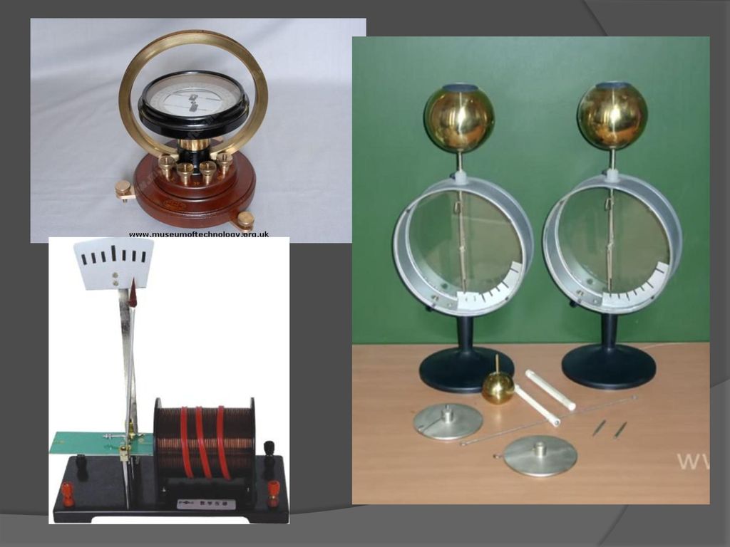


, the.>")


