Download presentation
Presentation is loading. Please wait.

1
Traditional Drafting Tools and Techniques
After completing this unit, the student should be able to: Describe the tools and techniques used in traditional drafting. Use technical pencils, straightedges, triangles, scales, protractors and templates to construct the geometry of technical drawings Read a conversion table to convert between decimal, fractional and metric units. Use traditional drafting tools to create multiview drawings of objects including the correct placement and depiction of visible, hidden and center lines. Hand-letter notes and dimensions on technical drawings that are clear and legible. 1

2
Traditional Drafting Tools and Techniques
Before Computer-Aided-Design revolutionized the way technical drawings are produced, drafters and designers sat at drawing tables and used traditional drafting tools like technical pens, triangles, scales, protractors, templates and straight-edges to draw on sheets of vellum or mylar (a thin sheet of plastic with a matte surface). In today’s engineering or architectural office, it would be rare for a drafter to create a drawing in the traditional way, but many of the techniques developed by traditional drafters, like orthographic projection, are still used to create 2D CAD drawings. The traditional tools discussed in this unit can be purchased through drafting supply outlets. Shown in Figures 3.1 through 3.3 are examples of traditional drafting equipment. A Drafting machine, or a parallel straight-edge, attached to the top of a drawing table allows a drafter to draw horizontal lines that are parallel to each other. Another tool that can be used to draw parallel horizontal lines is a T-Square. Figure 3.2 Drawing Table with Drafting Machine Figure 3.1 Drafting Machine-can be easily adjusted for drawing variable angles. Drafting Machines were once common in engineering offices.
. In today’s engineering or architectural office, it would be rare for a drafter to create a drawing in the traditional way, but many of the techniques developed by traditional drafters, like orthographic projection, are still used to create 2D CAD drawings. The traditional tools discussed in this unit can be purchased through drafting supply outlets. Shown in Figures 3.1 through 3.3 are examples of traditional drafting equipment. A Drafting machine, or a parallel straight-edge, attached to the top of a drawing table allows a drafter to draw horizontal lines that are parallel to each other. Another tool that can be used to draw parallel horizontal lines is a T-Square. Figure 3.2 Drawing Table with Drafting Machine. Figure 3.1. Drafting Machine-can be easily adjusted for drawing variable angles. Drafting Machines were once common in engineering offices.")
3
Traditional Drafting Tools and Techniques
Figure 3.3 Parallel Straight-edge Attached to the Top of a Portable Drawing Table

4
Technical Pencils and Pens
Professional grade technical pens and pencils are often used by design professionals to create technical drawings (See Figure 3.4). Figure 3.4 Technical Pencil Leads are inserted after removing both the top cap and the eraser. Technical pens and pencils come in differing line widths (.3mm, .5mm, .7mm, .9mm) and leads for technical pencils are available in a variety of hardness grades depending on the type of work to be performed. Table 3.1 shows the lead hardness grades and the appropriate application for the leads in each hardness range.
. Figure 3.4 Technical Pencil. Leads are inserted after removing both. the top cap and the eraser. Technical pens and pencils come in differing line widths (.3mm, .5mm, .7mm, .9mm) and leads for technical pencils are available in a variety of hardness grades depending on the type of work to be performed. Table 3.1 shows the lead hardness grades and the appropriate application for the leads in each hardness range.")
5
Beginning a Traditional Drafting Project
Figure 3.5 illustrates the proper technique for attaching a sheet of vellum to the top of a drawing table. Align the bottom edge of the sheet to the top edge of the drafting machine arm, parallel straightedge, or T-Square and tape all four corners to the table top. Horizontal lines can be drawn on the sheet by drawing along the top edge of the straight-edge. Figure 3.5 Aligning the Bottom Edge of a Sheet of Vellum to the Top Edge of a Parallel Straight-edge

6
Horizontal lines are drawn along the top edge of the straight-edge as shown in Figure A right-handed drafter holds the straight-edge in place with her left hand when drawing a horizontal line. Figure 3.6

7
Drafting Triangles Triangles, like the ones shown in Figures 3.7 and 3.8, provide drafters with angles commonly used in technical drawings-30, 45, 60, and 90 degrees. Triangles are usually made of acrylic plastic and are available in a variety of sizes. Figure 3.8 The 30/60 Degree Triangle. Figure 3.7 The 45 Degree Triangle.

8
There are triangles designed for drawing with lead and others for drawing in pen and ink. Inking triangles have a beveled, or stepped, edge to prevent the ink from running under the edge of the triangle and smearing.

9
Drawing Lines with Triangles and Parallel Straight-edges
To draw horizontal and vertical lines that are mutually perpendicular (90 degrees), drafters use a triangle in conjunction with a parallel straight-edge. To draw vertical lines, the triangle should be placed on top of the straight-edge as in Figure In this way you are assured that a vertical line will be at a 90 degree angle relative to a line drawn along the top of the parallel straight-edge. Hold both the straight-edge and triangle with your left hand while drawing the vertical line. You can use either the triangle (as shown), or the 45 degree triangle. Figure 3.9 Drawing a Vertical Line
, drafters use a triangle in conjunction with a parallel straight-edge. To draw vertical lines, the triangle should be placed on top of the straight-edge as in Figure 3.9. In this way you are assured that a vertical line will be at a 90 degree angle relative to a line drawn along the top of the parallel straight-edge. Hold both the straight-edge and triangle with your left hand while drawing the vertical line. You can use either the triangle (as shown), or the 45 degree triangle. Figure 3.9 Drawing a Vertical Line.")
10
Often beginning students erroneously believe that holding a triangle as vertical as their eyes can position it (known as “eye-balling”) and drawing a line will give them a perpendicular vertical line, when in fact, the only way to draw an accurate vertical line is to make sure the triangle rests on the straight-edge as shown in Figure However, there are occasions when floating the triangle is necessary, for example, when connecting two points, or the ends of two lines, when the angle of the resulting line is not equal to 30, 45, 60, or 90 degrees. In Figure 3.10, vertical and horizontal lines have been drawn and the drafter would like to draw a line connecting their end points. The desired angle does not match one of the triangle’s normal angles (30, 45, 60, or 90 degrees). In this case, the triangle would be floated and aligned with the ends of the vertical and horizontal lines. The line is drawn between the points along the edge of the triangle. Figure Floating the Triangle
. In this case, the triangle would be floated and aligned with the ends of the vertical and horizontal lines. The line is drawn between the points along the edge of the triangle. Figure 3.10 Floating the Triangle.")
11
Placing the 30/60 triangle on the top of the straight-edge as in Figure 3.11 allows you to draw lines 30 degrees from horizontal. These lines can be drawn either sloping to the right (as shown) or to the left by flipping the triangle over. Figure Drawing Lines at 30 Degrees

12
Figure 3.12 shows lines being drawn at a 60 degree angle from horizontal. By flipping the triangle over, lines can be drawn sloping to the left or right as needed. Figure Drawing Lines at 60 Degrees

13
The 45 degree triangle can also be used to draw 45 degree lines sloping either to the left or right as in Figure 3.13. Figure 3.13 Drawing Lines at 45 Degrees

14
Using two triangles in combination allows you to draw lines at 15 degree increments. In Figure 3.14, the 45 and 30/60 triangles are combined to draw lines at 75 and 165 degrees. Figure Combining Triangles to Produce Other Angles

15
In Figure 3.15, the 45 and 30/60 triangles are combined to draw lines at 105 and 15 degrees.
Figure Combining Triangles to Produce Other Angles

16
Making Measurements with the Engineer’s, Architect’s and Metric Scales
In engineering and architectural offices, designers and drafters use scales in two ways, the first is to take measurements off of existing drawings or plots and the second is to layout distances when constructing a drawing using traditional drafting techniques. Depending on the type of drawing being created, a designer may choose either the Engineer’s, Architect’s, or Metric scales to measure distances (a Combination scale is also available that has a mix of the most commonly used scales).
.")
17
Reading the Engineer’s Scale
The Engineer Scale is used by both Mechanical and Civil engineers. The marks on the scale may be interpreted differently depending on the discipline. In Figures 3.16 the Engineer’s 10 scale is used to measure decimal inches. In Figure 3.18 the Engineer’s 10 scale is used to measure distances in feet. Figure 3.16 Measuring Decimal Inches with the Engineer’s 10 Scale Figure 3.17 Measuring Feet with the Engineer’s 10 Scale-This Scale would be interpreted as 1”=100’

18
Reading the Metric Scale
Mechanical engineers can use the Metric scale shown in Figure 3.18 to measure distances in millimeters. In Figure 3.18, each small mark on the scale equals 1 millimeter. Figure 3.18 Measuring Millimeters with the Metric Scale

19
Reading the Architect’s Scale
The Architect’s scale is used to measure feet and inches on a floor plan. The Architect’s 1/4 scale shown in Figure 3.19 would be interpreted as 1/4”=1’-0”. This means that ¼ inch measured on the drawing would equal 1 foot at the construction site. Figure Reading Feet and Inches on the Architect’s ¼” equals 1’ Scale

20
Figures 3.20, 3.21, and 3.22 show examples of other commonly used architectural scales.
Figure Interpreting Inch Marks on the Architect’s 1/2 and 1/8 scales

21
Figure 3.21 Measuring Fractional Inches with the Architect’s 16 Scale

22
Figure 3.22 Measuring Feet and Inches with the Architect’s 1”=1’-0” Scale

23
To avoid having to search for a desired scale on a triangular scale use a binder clip to mark your scale. For example: If using the 10 scale on an Engineers scale, attach the binder clip to the 50 scale. When you pick up your scale the binder clip will orient you to the 10 scale.

24
Converting Units of Measurement
Sometimes, drafters must convert from one unit of measurement to another. Some commonly used conversion factors are listed below: Fractional inches can be converted to decimal inches by dividing the numerator (the top number) by the denominator (the bottom number). Decimal inches can be converted to millimeters by multiplying them by 25.4 Millimeters can be converted to decimal inches by dividing them by 25.4 Table 3.2 is useful for quickly finding the equivalent value between the various units listed.
 by the. denominator (the bottom number). Decimal inches can be converted to millimeters by. multiplying them by Millimeters can be converted to decimal inches by. dividing them by Table 3.2 is useful for quickly finding the equivalent. value between the various units listed.")
25
Figure 3.23 A Half-moon, or 180 Degree, Protractor.
Reading the Protractor A protractor is a tool used to layout angles on a drawing. Full circle protractors are divided into 360 degrees while half moon protractors (see Figure 3.23) are divided into 180 degrees. Both are divided in 10 degree increments. Note how the protractor is divided from 0 to 180 degrees both clockwise and counter-clockwise. Figure A Half-moon, or 180 Degree, Protractor.
 are divided into 180 degrees. Both are divided in 10 degree increments. Note how the protractor is divided from 0 to 180 degrees both clockwise and counter-clockwise. Figure 3.23 A Half-moon, or 180 Degree, Protractor.")
26
Figure 3.24 A 330 Angle Using the Inner Dial.
Figures 3.24 through 3.27 illustrate some of the ways the protractor can be used to measure angles. Figure A 330 Angle Using the Inner Dial.

27
Figure 3.25 A 330 Angle Using the Outer Dial.
Figures 3.24 through 3.27 illustrate some of the ways the protractor can be used to measure angles. Figure A 330 Angle Using the Outer Dial.

28
Figure 3.26 A 570 Angle Measured from Vertical.

29
Figure 3.27 Measuring an Angle Greater than 1800 using a Half-moon Protractor.

30
The Circle Template Circle templates come in a wide range of units-decimal inches, fractional inches and millimeters-and diameters. Figure A Circle Template.

31
The Circle Template-Continued
Figure Using the Circle Template. 2. Find the desired circle size and align the ticks on the template with the crosshair. 3. Draw the circle by following the template. 1. Locate center and draw crosshair.

32
The Isometric Ellipse Template
On isometric drawings, circles are represented as ellipses. Isometric ellipse templates allow drafters to quickly place ellipses on isometric drawings. Figure 3.30 Using an Isometric Ellipse Template. A. When drawing an isometric ellipse, disregard the minimum diameter ticks unless using them to align the objects vertically. B. Disregard the maximum diameter ticks unless using them to align the objects horizontally. 1. Locate center and draw crosshair at 30 degree angles. 2. Find the desired ellipse size and align the ticks on the template with the crosshair. 3. Draw the isometric ellipse by following the template.

33
Steps in Constructing a Simple Drawing
Steps 1 through 9 illustrate how a drafter may use the triangle, scale, and parallel straight-edge to construct a simple technical drawing. At the end of this unit are drafting projects in which you will have an opportunity to apply the techniques shown in these steps. Step 2. Align the scale along the construction line and place light “tick marks” to denote the desired measurement as shown in Figure 3.32. Step 1. Draw a 30 degree construction line. See Figure 3.31. Figure 3.32 Marking the Desired Length with Light Tick Marks Figure 3.31 Drawing a Light Construction Line

34
Step 3. Align the edge of the triangle with the construction line and draw a dark visible line along the top edge of the triangle between the tick marks. See Figure 3.33. Step 4. The darkened visible line is drawn the desired distance as shown in Figure 3.34. Figure Darkening the Line Between the Tick Marks Figure The Finished Line

35
Step 6. Measure the along the horizontal construction line with the scale and mark off the desired distance with a small tick mark. See Figure 3.36. Step 5. Slide the straight-edge until it is aligned with the lower end of the darkened line and lightly draw a horizontal construction line. See Figure 3.35. Figure 3.36 Using a Scale to Make a Measurement on the Horizontal Line Figure 3.35 Drawing a Horizontal Construction Line

36
Step 8. Because the angle between the ends of the lines does not match an angle on either triangle, float the triangle until it is aligned with the ends of each line and draw a dark visible line connecting them. See Figure 3.38. Step 7. Draw a dark visible line between the tick marks. See Figure 3.37. Figure 3.38 Floating the Triangle to Connect the Endpoints of the Lines Figure 3.37 Darkening the Horizontal Line

37
Figure 3.39 The Finished Drawing
The completed drawing is shown in Figure 3.39. Figure The Finished Drawing

38
Steps in Constructing a Multiview Drawing
The steps involved in constructing a multiview drawing with traditional tools are illustrated in Figures 3.40-Figure 3.44. Step 1. Study the width, depth, and height of the object to be drawn and use these dimensions to determine the location of the views. Views are usually equally spaced both horizontally and vertically as shown in Figure A formula for determine the horizontal spacing is to take the width of the sheet and subtract the width of the front view and the depth of the side view and divide the remainder by 3. To find the vertical spacing, take the height of the sheet and subtract the height of the front view and the depth of the top view and divide the remainder by 3. Figure 3.40 Determining View Spacing

39
Step 2. The width, height and depth of the views is laid-out with light construction lines. See Figure 3.41. Figure 3.41 Rough Layout of Views.

40
Step 3. A miter line is added so that orthographic projection techniques can be used to project between the top and side views. Circles and arcs are drawn in lightly with a circle template or compass. Information is projected between views with light construction lines. See Figure 3.42. Figure 3.42 Adding Miter Line and Circles.

41
Step 4. Hidden and center lines are added as shown in Figure 3.43.
Figure 3.43 Adding Hidden and Center Lines

42
Step 5. Construction lines are erased and the visible, hidden, and center lines are darkened to complete drawing. See Figure 3.44. Figure Finished Drawing

43
It is best to draw all the views using construction lines.
If you make a mistake it is easier to erase a construction line than a dark visible, hidden, or center line. Once you have drawn the views with construction lines, heavy up the Top view first, then the Front view, and the Side view last. Darkening your lines in this order allows you to work away from your completed views and minimizes smudging.

44
The Technical Lettering Sermon
Every technical drawing text is required by law to expound on the importance of good technical lettering skills. Well, not really, but technical drawing teachers, as sworn defenders of an ancient art form, feel an obligation to convey the importance of this skill to their students so here goes. During the design process, drafters and designers often make sketches which contain hand-written notes and dimensions. It is very important that any hand-lettered text on a drawing be neat and legible. In fact, lettering that is not neat and legible would be considered unprofessional in most engineering or architectural offices because poor lettering on a design sketch could result in dimensions or notes being incorrectly depicted on a technical drawing which could lead to a costly mistake on a construction site, or manufacturing floor. Therefore developing good lettering skills is very important to the training of a drafter/designer. But good lettering is a skill that is only mastered through practice. Over time, most drafters and designers develop their own unique lettering style. Some drafters, especially in the architectural field, develop a lettering style that could be considered an art-form. While you may never develop a style that qualifies as “art”, with practice you can develop a style that is neat, legible and consistent.

45
Developing a Technical Lettering Style
Study the examples of the letters and numerals shown in Figure Notice how the characters are made with a uniform height, width and style. Also notice how each character is clear and legible. In the guidelines provided in Figure 3.45, practice lettering the alphabet and numerals. Try to match the lettering style shown in the example. Lettering should be dark, so press down hard with the pencil when making the strokes that form a letter or numeral. Figure 3.45 An Example of a Good Technical Lettering Style

46
Summary Although traditional drafting tools are rarely used in modern engineering and architectural offices, many of the same techniques developed by traditional drafters are still used in the creation of drawings with CAD. For example, the location of points and planes is still projected between multiviews, only instead of using a drafting triangle, an AutoCAD drafter uses a drafting setting called Ortho to draw perfectly straight horizontal and vertical lines. An understanding of how angles are measured with a protractor facilitates drawing angles with CAD. Drafters and designers often use scales to take measurements off of plotted drawings (which is not always a good idea by the way) and an understanding of how to interpret an Engineer’s, Architect’s or Metric scale facilitates thinking about scaling in AutoCAD drawings. The creation of free-hand sketches with legible lettering remains an important skill in today’s design office. Every professional drafter/designer, whether traditional or CAD, should develop a free-hand lettering style that is neat, uniform, and legible to facilitate communication between designers, or between designers and their clients.
 and an understanding of how to interpret an Engineer’s, Architect’s or Metric scale facilitates thinking about scaling in AutoCAD drawings. The creation of free-hand sketches with legible lettering remains an important skill in today’s design office. Every professional drafter/designer, whether traditional or CAD, should develop a free-hand lettering style that is neat, uniform, and legible to facilitate communication between designers, or between designers and their clients.")
47
Technical Lettering Exercise 3-1
STUDENT NAME: Practice lettering the alphabet and numerals in the guide lines shown in Figure Try to match the example lettering style shown int this example. Figure Lettering Exercise

48
MATERIAL: MOLYBDENUM STEEL MATERIAL: MOLYBDENUM ALLOY STEEL
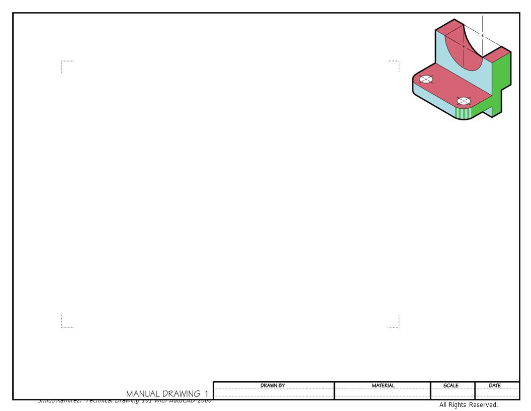
Unit 3 Traditional Drafting Projects Project 3-1 Traditional Drafting Project 1 (SI) Figure Traditional Drafting Project 1 Directions: On the sheet at the back of the text, draw the front, top, and right view of the object in Figure This drawing employs International Units (SI) so you will use the METRIC scale marked 1:100 (refer to Figure 3.18) to draw the object FULL size (1=1). Apply dimensions to the views as instructed by your teacher. Letter your name, material and scale in the guidelines provided. Refer to Figure 3.47. MATERIAL: MOLYBDENUM STEEL MATERIAL: MOLYBDENUM ALLOY STEEL
 Figure 3.47 Traditional Drafting Project 1. Directions: On the sheet at the back of the text, draw the front, top, and right view of the object in Figure This drawing employs International Units (SI) so you will use the METRIC scale marked 1:100 (refer to Figure 3.18) to draw the object FULL size (1=1). Apply dimensions to the views as instructed by your teacher. Letter your name, material and scale in the guidelines provided. Refer to Figure MATERIAL: MOLYBDENUM STEEL. MATERIAL: MOLYBDENUM ALLOY STEEL.")
50
Figure 3.48 Finished Project

51
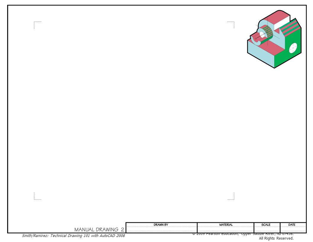
Traditional Drafting Project 2
Figure Traditional Drafting Project 2 Project 3-1 Traditional Drafting Project 2 Directions: On the sheet at the back of the text, draw the front, top and right view of the object in Figure Using the Engineer 10 scale (refer to Figure 3.16), draw the object FULL size (1=1). Apply dimensions to the views as instructed by your teacher. Letter your name, material and scale in the guidelines provided. Refer to Figure 3.49. MATERIAL: CAST IRON
, draw the object FULL size (1=1). Apply dimensions to the views as instructed by your teacher. Letter your name, material and scale in the guidelines provided. Refer to Figure MATERIAL: CAST IRON.")
53
Figure 3.50 Finished Project

54
Additional Traditional Drafting Projects
Directions: On the sheets provided by your instructor, draw the front, top and right view of the objects in Figures 3.50 through Use the appropriate scale for the units provided in the designer’s sketch. Apply dimensions to the views as instructed by your teacher. Letter your name, material and scale in the guidelines provided. Figure Traditional Drafting Project 3 Figure 3.52 Traditional Drafting Project 4 Figure 3.53 Traditional Drafting Project 5

55
Homework: Before beginning Unit 4, read Unit 4 in the text up to AutoCAD Exercise 4-1.

Similar presentations