Mohr’s circle represents a graphic technique which transforms stress from one plane to another. This graphical technique is what leads to the determining of maximum normal and shear stresses.
March 2, 2024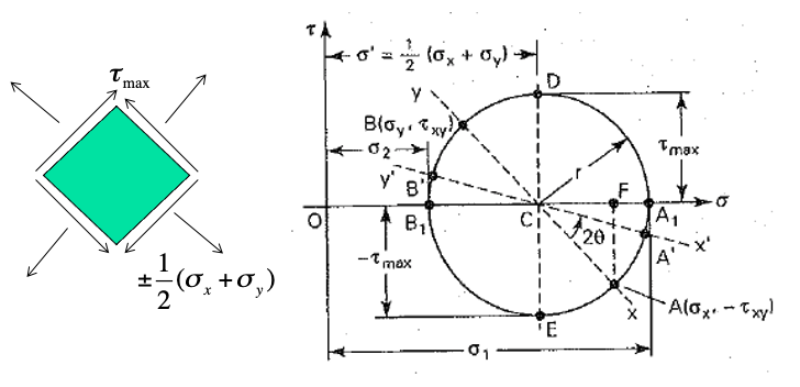
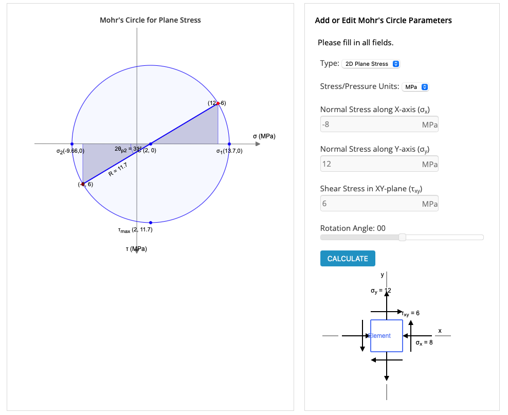
In the figure above, the right hand figure shows the circle relative to what the normal stress values are.
The left hand side shows the plane stress transformation with the shear stress and normal stress values.
What is Mohr’s Circle?
Mohr’s circle is a method used to for plane stress transformation and determines what the max normal and shear stresses are.
Moth’s Circle Equations
Let’s take into account a wedge noted as QAB cut from the loaded body in the below figure.
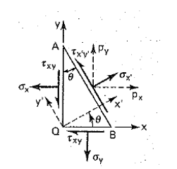
It is required to determine the stresses σ’x and τ’xy, which refer to axes x’, y’ making an angle θ with axes x, y as shown in figure above.
Mohr’s Circle stress transformation equations based on the wedge geometry will be:
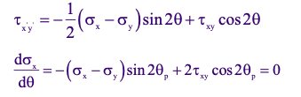
The stress σy’ may be obtained by substituting θ + π/2 in the theta expression for σ’x
Let’s recall the trigonometric identities, so that we can substitute in a later equation:
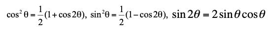
As a result of using the trig identities, stress transformation equations will be represented in the forms:
Stress Transformation Equations
In which both forms of the transformation equations are needed for different applications.
Principal Stresses
Let’s take a look at the x axis and determine what the principle stresses are in that respective axis.
To obtain the maximum or minimum value of σ’x , the necessary condition dσx’/dθ is applied
This results in the following set of equations:
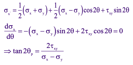
Due to trigonometry, since, tan2θ = tan(π + 2θ), two mutually perpendicular directions satisfy the above equation.
These are called the principal directions, along which the maximum and minimum normal stresses act.
The two values of θp , corresponding to σ1 and σ2 , are sometimes denoted by θ’p and θ”p = 90o + θ’p
Now let’s compare the set of equations in the figure above, we see that τx’y’ = 0 for θ = θp, i.e. on a principal plane
Thus a principal plane is represented by a plane of zero shear.
As a result, if we substitute the above set of equation within each other, we will get the principal stresses.
The principle stresses are represented by the following equation:
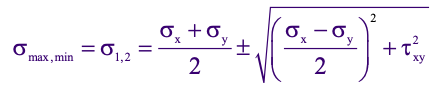
The larger stress will be the maximum principal stress, whereas the smaller stress value will be the minimum principal stress.
Maximum Shear Stress
If we take the same approach, we get what the maximum shear stress is by setting dτx’y’ /dθ = 0:
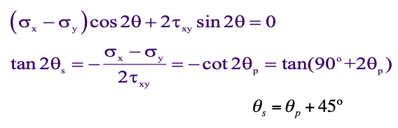
The above expression defines two values of θs that are 90° apart.
The planes of maximum shearing stresses are inclined at 45° with respect to the planes of the principal stresses.
As a result of substitution of the above equations and assumptions, we get the maximum values of shear stress.
The maximum shear stress equation is represented by the following equation:
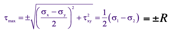
It is important to note that the maximum shear stress represents the radius R in Mohr’s circle.
How to draw Mohr’s Circle
- Establish a rectangular coordinate system, indicating +τ and +σ
- Locate the center C of the circle on the horizontal axis at a distance of ½(σx + σy) away from the origin
- Locate point A by coordinates σx and – τxy
- Draw a circle with center ct C and of radius equal to CA
- Draw line AB through C
- Use geometry to calculate σx‘, σy‘, and τxy‘
It is important to note that the Mohr’s circle gives a “bird’s eye” view of the important properties of the stresses.
However, it is a geometrical construct and the formulas derived earlier are more useful for the calculation of the transformed stresses
Mohr’s Circle Example
Hollow Shaft Application
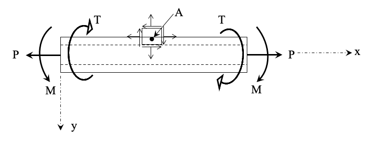
A Hollow shaft of 60-mm outer diameter and 30-mm inner diameter is acted by an axial tensile load of 50 kN, a torque of 500 N·m, and a bending moment of 200 N·m. Determine the principal stresses and their directions.
This example problem will use principles derived from the above Mohr’s circle equations.
The problem can also be solved graphically using a Mohr’s circle approach.
Solution
Let’s take into account an element on the surface of the hollow shaft and indicate all the stresses applied on the element.
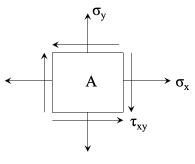
As a result, we get the following:
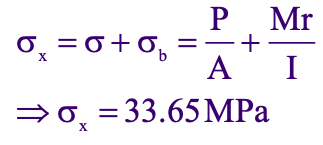
The normal Stress in the x direction is due to tensile loading and bending moment :
The normal Stress in the y direction is zero:

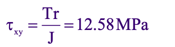
The shear stress is due to torsion:
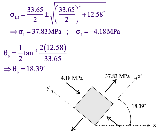
Using the principal stresses equations above, we get the following for principal stresses:
Mohr’s Circle Calculator
If you want a quick way to calculate and draw a Mohr’s circle, check out BendingMomentDiagram’s Calculator:
3D Mohr’s Circle
To look at a 3D representation of stresses, we need to look at linear algebra.
It can be shown that the principal stresses are given by the eigenvalues and the principal axes are along the corresponding eigenvectors of the stress matrix.
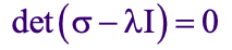
Thus to determine principal stresses, calculate the eigenvalues λ1, λ2 and λ3 of [σ], i.e. solve for λ from
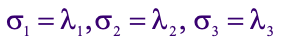
The principal stresses are then represented by the following Eigen values:
Principal Axes
To determine the principal axes, calculate the eigenvectors V(1), V(2), V(3) of[σ] corresponding to the eigenvalues λ1, λ2, λ3
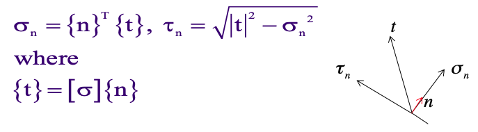
Normal stress
To calculate normal stress σn and shearing stress τn on an oblique plane with unit normal n (n1, n2, n3), use the following formulas
Closing Thoughts
Although Mohr’s circle is very heavily talked about in a Strength of Materials class, it is not talked about much in the industry.
The reason being that for stress or structural analysis, we use tools such as FEA software.
FEA software tools such as ANSYS, CREO, SolidWorks Simulator will perform these principal stress calculations for us.
The most important part regarding principal stresses and shear stresses are what they are and what the physical values you get mean.
It is important that for your analysis, that you set up your boundary conditions properly. As a result, this will give you accurate results in the real world in which you give to the customer.
Stress analysis from a business standpoint is making sure a system handles what it is capable for.
About the author

Kazuyoshi Fujimoto, PE
Founder | Engineering Career Coach | Principal Mechanical Engineer
Kazu oversees all of ultmeche’s engineering services. He provides consulting such as resume reviews, rewrites, mock interviews, and all services career related. Additionally, Kazu performs consulting work regarding Oil & Gas, Automotive, and Aerospace & Defense. Kazu is licensed as a professional engineer in the state of California and has 9+ years of experience in Oil & Gas, Automotive, and Aerospace & Defense.