Introduction
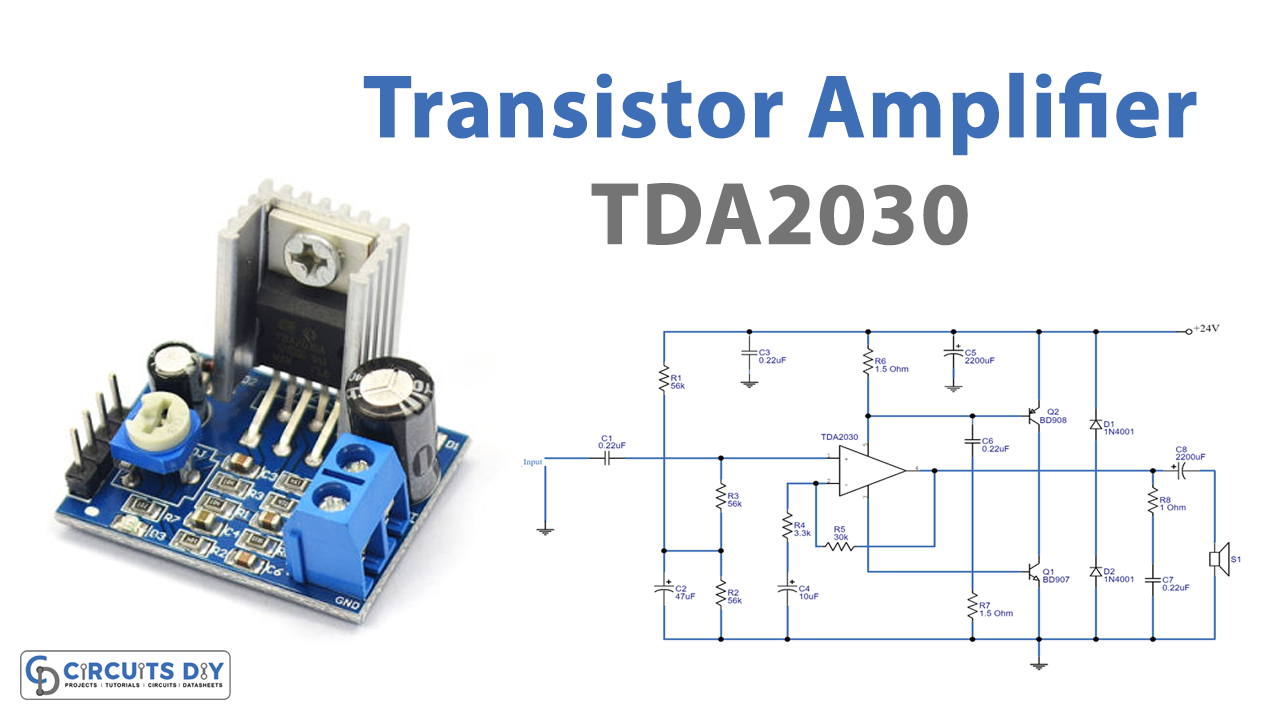
In this Tutorial, we are going to make a “TDA2030 transistor amplifier circuit”. The TDA2030 integrated circuit is the ideal choice for creating the amplifier circuit. Because it is a low-cost, simple-to-use integrated circuit, appropriate for electronic novices. This circuit is built with a variety of electronic components. Turning up the level on this circuit allows you to hear the sound.
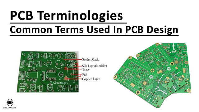
In the making of the circuit, we are using a PCB board instead of a breadboard or Vero board. Because, Over ordinary wiring, troubleshooting damaged components or connections on PCB is relatively simple. The failure components on the PCB can be easily tested with a multimeter during a short circuit or fault state. PCB boards are widely available on the market at reasonable prices.
Hardware Required
| S.no | Component | Value | Qty |
|---|---|---|---|
| 1 | Transistor | BD907 & BD908 | 1, 1 |
| 2 | Resistor | 56K, 3.3K, 30K, 1.5 ohms, 1 ohm | 3, 1, 1, 2, 1 |
| 3 | Capacitor | 0.22uF, 47uF, 10uF, 2200uF | 4, 1, 1, 2 |
| 4 | IC | TDA2030 | 1 |
| 5 | Diode | 1N4001 | 2 |
| 6 | Speaker | – | 1 |
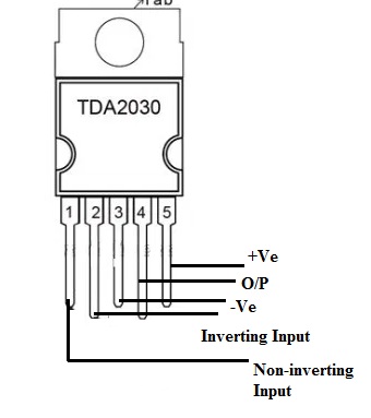
TDA2030 Pinout
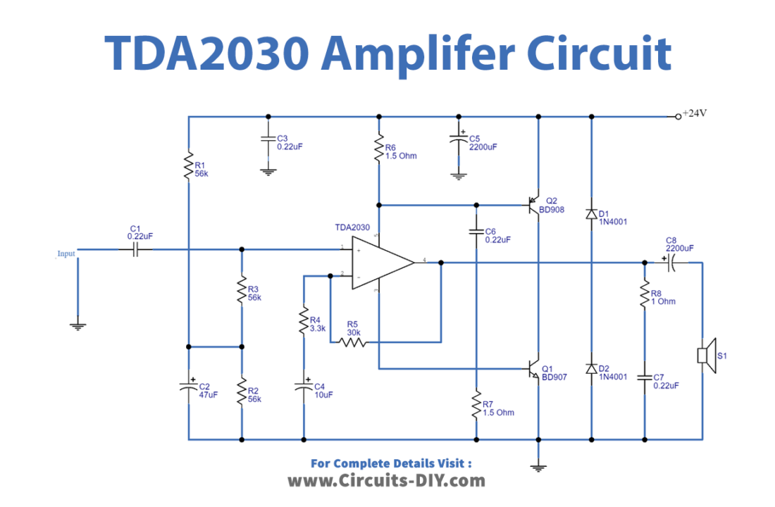
Circuit Diagram
Working Explanation
When we plug in the power supply and the audio signals in the TDA2030 transistor amplifier circuit, the capacitor C1 is there to prevent DC from entering the circuit. As a result, audio signals can readily enter IC1’s pin 1. Furthermore, this circuit employs a single power source with two terminals: positive and ground. To divide the voltage in half, connect two resistors R1, R2, and capacitor C2. Moreover, R3 corresponds to the input IC1. The gain of IC1 is set to 14 in the circuit. Because the pattern is a non-inverting amplifier.
Pin 4 sends the output signal. However, it remains low. We require assistance with the transistors. Q1 and Q2 transistors both boost the signal, The current is sent through resistor-R6 the positive terminal. In addition, Resistor R7 sends current to the negative terminal. When greater currents pass via R6 and R7., their voltage drop exceeds, which is bias voltage to transistors Q1 and Q2.
The higher output signal is sent to the speakers through capacitor C8. While R8 and C7 can prevent the loss of high-frequency output to the loudspeaker.
Both diodes D1 and D2 are employed to prevent the speaker’s return voltage from interfering with the IC1, Q1, and Q2. Furthermore, both filter capacitors C7 and C8 help smooth the power before it is given to the circuit.
Application Uses
- In audio speakers
- Headsets, microphones, speakers, and other audio equipment
- This circuit can set up home theatre systems, etc