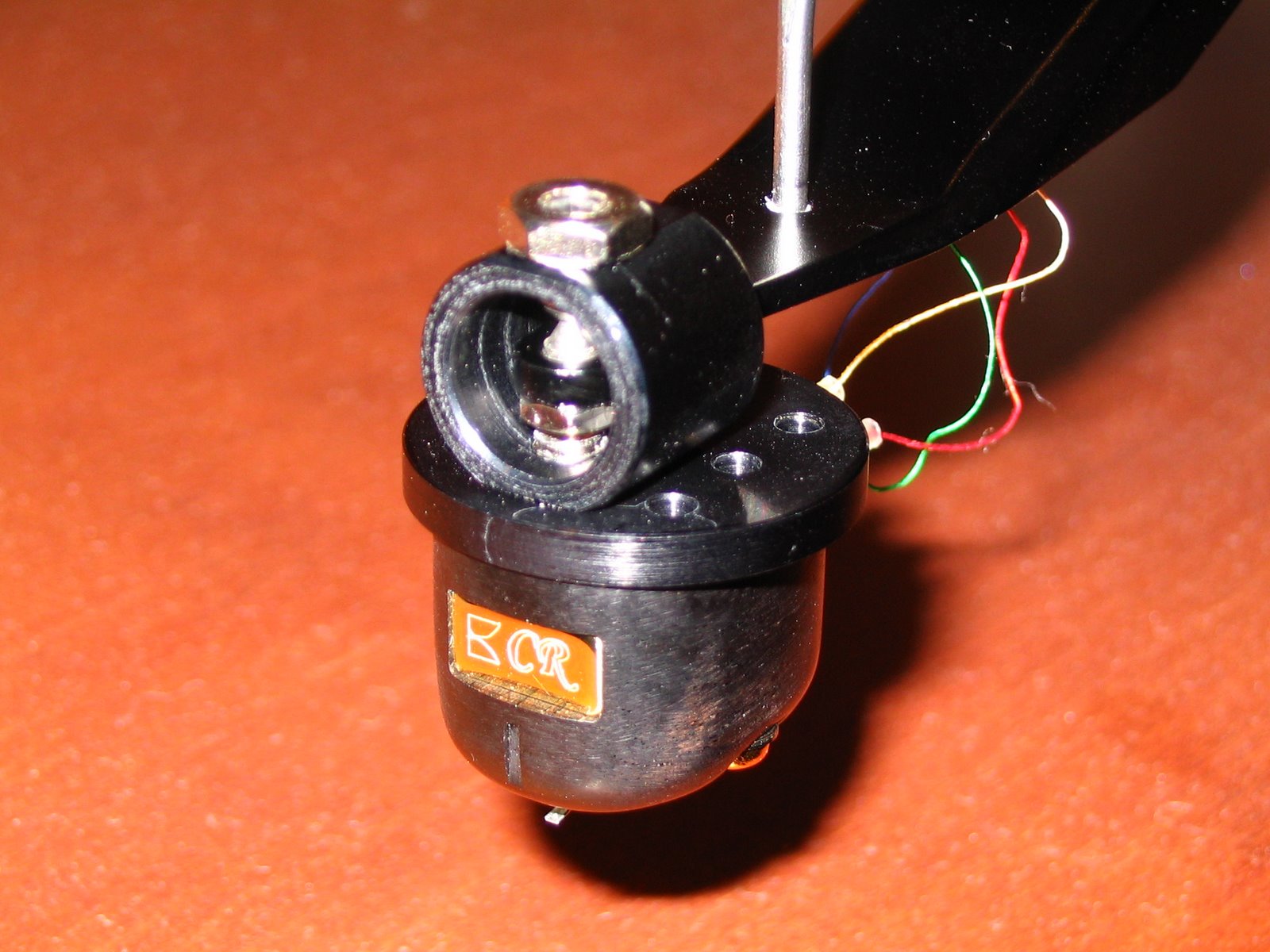
Did I murder my Philips CD303?

I got a Philips cd 303 with noisy outputs, so I replaced all the caps on the power supply and laser board, repaired broken soldier joints... And it worked fine.
Then I decided to change dac power supply caps, but when I was connecting dac board I misplaced two 3 cable connectors, the data and power supply I think.
Now only drawer works and mab8410p chip is getting really hot. I tried putting a chip from a cd 304, which is a little different, and with it it spins the disc but won't read, display doesn't work... but the chip is staying cool.
So, did I fry the mab8410p? Are there any replacements avalible?
Any help would be greatly appeciated.

ES9033Q Question...

Hello everyone,
I'm planning to design a DAC with the ES9033 chip. For this purpose, I read the ES9033 datasheet several times. I want to design a tiny and efficient board, for example I'm considering a low noise ldo like LP5907-33 for supply. The DAC will operate entirely in hardware mode and DSD will not be used.
I have solved all the other issues in my mind, but I am confused about the I2S input. Namely;
According to the ES9033 datasheet, the chip's I2S inputs for PCM are DATA1-DATA2-DATA_CLK and MCLK. It is clear that DATA_CLK = BCK and MCLK = MCLK. However, as far as I understand, DATA1 is the Left Channel Data, for example, while DATA2 is the Right Channel..
In this case, do I need to separate the DATA line as right and left with a simple logic and LRCK clock at the I2S input and enter these lines?
Or is there a system in the chip to use these two DATA lines with LRCK?

1707895117257.png

ScanSpeak 2.5 way TL exercise by Sasha

Big hello with Christmas 2023. Scan Speak project. :)

2.5 way tapered transmission line with Scan Speak units. Always wanted to build something with legendary 18W Revelators and this year two pairs landed in my workshop. One pair is from 2022 and bought 6 months ago. One pair produced in 2023 I bought now as a Christmas present from me to myself. All four look the same and I hope they will sing the same. Illuminators D3004/6600 will come in January and be installed in augerpro's waveguide to complement the package.

Revs 18W.jpg


Why TL? Because I would like to hear that deep dry bass :cool: and I don't want to build another too small 6+1 inch speaker whistling around 50 Hz through its too small port. I want to build something bigger and different. That's why double dose of 18Ws as a bare minimum with Sd surface of 10 inch driver. Later to overstuff it and test how too big aperiodic / sealed box with low Q would sound and would I like it or not - for my future projects.

Idea is for a longer time in my head, I went through Onley, Bailey, Augspurger and MJK and all available here on diyA. I have come to the level where I can produce TL in Hornresp in a few seconds :) and it was good course about behaviour, changes and important parameters in Tls. MJK made nice writings recently as an extension of his work from two decades ago. He is trying to demistify and make fair comparisons to various bass enclosures. It was a good guide for complete TL design from scratch.


So, few goals:


1. 2.5 way tapered TL towers with 2x SS 18W/8531G00 plus D3004/6600 in waveguide;
2. Internal volume around ~ 60 liters plus minus 3 dB;
3. Tuning not below 30 Hz and especially not above 35 Hz;
4. Bass quality above quantity and lowest minus 3dB point;
5. 5:1 taper as an optimum between length, width of the box, physical buildable size, Start and End cross sections and slow blow mouth velocity;
6. Low diffraction cabinet with thick rounded front baffle (I have CNC router) for directivity control of midbass for better match with waveguide;
7. Additional external curved sides to make elegant teardrop-ish cabinet, glued with CLD layer;
8. Simple minimal audiophile passive crossover :love:;
9.. High end sound of course;
10. Sexy look blink blink;

In next few posts drivers measurements with DATS, calculations of geometry according to MJK methodology and Hornresp simulations...

Goal for this Christmas vacation time is to cut and build-with-screws test boxes as a hardest part. If they pass initial measurements then will be glued and further developed into something serious...

folded profile.jpg
  • Like
Reactions: 6 users

Speaker Turn On Delay and DC Protector Board Set (V3)

This thread is for discussions about the new Speaker Turn-On Delay and DC Protector boards (V3). This is an updated version of the V2 boards, primarily to make them compatible with the 10x10 grid mounting pattern we've now standardized on so they can be easily mounted to Deluxe chassis baseplate, riser panels, front panels and/or heatsinks. Refer to the V2 discussion thread for additional information.

For more information on this product, please see the product page.

Change History
  • 2.0 First Production Release
  • 2.0.1 Added Board Dimensions
  • 3.0 New Layout
    • Double sided board
    • Added Keystone connectors as option
    • Conforms to 10mm mounting grid
  • For future changes
    • Add polarity markers for electrolytic capacitors

Information
  • Product Page
  • BOM - Attached below (Now updated to V3.0.2b) -- 3-paged BOM
  • Schematic - Coming soon
  • Dimensions - 100mm x 50mm

Attachments

  • Speaker Protection Board BOM V3.0.2b.xls.zip
    38.8 KB · Views: 1,654

JVC SP UX7000 mini speakers

I bought these to have a play with them having read some good things about the small driver. Didn't do much with them apart from quickly adding a 15uf cap to roll them off as I used them for a short time sat on top of a LF module. They really didn't like any bass!
£25 plus post
IMG20240407125416.jpg

Attachments

  • IMG20240407125402.jpg
    IMG20240407125402.jpg
    365.4 KB · Views: 25
  • IMG20240407125410.jpg
    IMG20240407125410.jpg
    270.6 KB · Views: 27
  • IMG20240407125429.jpg
    IMG20240407125429.jpg
    410.5 KB · Views: 22
  • IMG20240407125443.jpg
    IMG20240407125443.jpg
    483.3 KB · Views: 23
  • IMG20240407125455.jpg
    IMG20240407125455.jpg
    236.7 KB · Views: 26
  • IMG20240407125509.jpg
    IMG20240407125509.jpg
    385.2 KB · Views: 29

preamp for playback from reel to reel tape deck

I have a Sony reel-to-reel Tape Deck (1960s vintage) whose pre-amp has failed (the capacitors have fallen apart). Mechanically, the deck works OK. I no longer need to use the deck for recording but I'd like to play all my old tape recordings and convert the ones I want to keep into digital. To do this, I think all I need to do is take the 4 wires (2 each for the L and R stereo channels) from the playback head and feed them into my modern Marantz amplifier/receiver. However, I expect I'll need to feed them through a suitable preamp. If so, where can I get one?

SD Acoustics SD1

I'm new here and a new owner of a pair of sd1s (conventional tweeter). They're infinite baffle speakers with a nice functional look roughly the size of Celestion sl6s from I guess the late 80s.
They sound very good to me, timing through the mids and highs seems good, but I wondered if anyone had experience positioning these? I currently have them on Linn Kan stands—an open frame design about 53cms high, and about a foot out from shallow bays surrounding a chimney breast (a foot out from the breast that is). They're about 3 feet from either sidewall. If I push them back I seem to get a little more presence but slightly forward gives a little more information to string tone; but otherwise these seem curiously unresponsive to positioning in my high ceilinged largish, squarish and bare room (whilst basically still sounding good). Anybody else have a recommendation?
And thanks in advance.

I’d prefer a separate forum for Horn speakers

Over the years I’ve found myself trying to filter the Multiway thread into horn speakers and non horn speakers. I don’t know the history of these forums but multiway vs full range has never seemed like the best way to categorize projects of interest for me. I tend to think more in terms of horns, towers and OB. Anybody else feel there’s a better option than what we have now?
  • Like
Reactions: 1 users

The avatars…

There are some really cool avatars in use, and some really so-uncool-they‘re-cool-again avatars…

I confess: I „identify“ some of the fine folks who use a foto of somebody with these and this can be a bit disturbing. OTOH, some are just perfect, and they are biasing whatever is written under their name to the positive. (Looking at you, @Mark Johnson , @SRMcGee , @meldano , @ggetzoff )

A bit naive, isn’t it? 🙃🥳

DIY optical cartridge preamp

DS Audio recently decided to open up their optical phono stage details for the world to use in order to help optical cartridges become more widely used and compatible with more preamps, etc., rather than only being compatible with DS Audio phono stages.

My first thought was that this could open up the possibility of a DS Audio cartridge + DIY optical phono preamp :)

Some info is published here: https://www.ds-audio-w.biz/wp-content/uploads/2021/03/EQ-infover1.02.pdf

According to this article, DS Audio is open to technical enquiries about their technology, though this may apply to manufacturers only: DS Audio is sharing its optical phono cartridge secrets for free | What Hi-Fi?


Who wants to go first? :D

Salvaging a dimarson DM-R300 5.1 home theater speaker set.

Hello guys.
Forgive me if i have posted this in the wrong forum. Unfortunately my dvd player/home theater 5.1 system has died.
The 6 speakers are in perfect condition though. So rather than buying a new one i thought of getting an amp for it.
Mainly because it would be a lot cheaper ( i suppose), and there is no reason to let the 6 speaker collect dust.
I tried to find something for the specification, but i had no luck.
My computers motherboard has 6 rca output, so i am looking for a suitable (preferably cheap) amp/crossover that could utilize my speakers.
The 4 corner speakers+center are 15W 6 ohm , and the Sub is 30W 4 ohm.
Any help is appreciated, thank you all in advance!

AMC CD6 - looking for a Service Manual

A friend will shipping his fault device of this model, but I told him that I would first try to get a service manual with schematic diagram.
Maybe one of the member can upload this.
Thank you very much.
P.S.: On the portal from Elektrotanya I only find the CDM7 from the same Dutch company.

Attachments

  • AMC CD-6 front.jpg
    AMC CD-6 front.jpg
    74.6 KB · Views: 28
  • AMC CD-6 front-top.jpg
    AMC CD-6 front-top.jpg
    82.3 KB · Views: 31
  • AMC CD-6 rear+RC.jpg
    AMC CD-6 rear+RC.jpg
    75.1 KB · Views: 22
  • AMC CD-6 rear.jpg
    AMC CD-6 rear.jpg
    87.7 KB · Views: 30
  • AMC CD-6 ZC99685P servo proc.jpg
    AMC CD-6 ZC99685P servo proc.jpg
    146.8 KB · Views: 32
  • AMC CD-6 NE5534 from EXAR.jpg
    AMC CD-6 NE5534 from EXAR.jpg
    148.2 KB · Views: 26
  • AMC CD-6 main PCB.jpg
    AMC CD-6 main PCB.jpg
    107.4 KB · Views: 26
  • AMC CD-6 CDM-4.jpg
    AMC CD-6 CDM-4.jpg
    90.6 KB · Views: 23
  • AMC CD-6 botton.jpg
    AMC CD-6 botton.jpg
    72.7 KB · Views: 24

Found a couple of "LM1875T"

Hey people,

I found these "LM1875T" ( I assume the common, not so bad sounding, fakes as everywhere). I just forgot I have them, as I changed to LM3886 just because of the higher output power. I remember them as really good sounding chips, and it would be a pity to not put them to use.
I thought, maybe I could try two of them for my tweeters, which are powered by LM3886's atm. It's all fully active, so the different output power can be aligned easily.

best regards

For Sale Assembled B1 with Korg Triode - high end - +24V

I'm gauging interest, here.

I built an integrated amplifier with B1 as preamp, but I didn't like the amplifier section. So I tore it apart and sold the amplifier section. Now I'm debating what I should do with my assembled B1 with Korg Triode.

If I hold on to, it might sit for a while. It's only been for a couple of months and it's already covered in dust; sorry for the pics. So selling it might make sense. Let me know if you are interested.

This board is the OG. It's the Christmas board. It's been fitted with high end parts (Vishay Dale resistors and Nichicon audio capacitors) and spec'd out to handle up to 35V.

Attachments

  • IMG_0041.JPG
    IMG_0041.JPG
    502.9 KB · Views: 62
  • IMG_0040.JPG
    IMG_0040.JPG
    490.2 KB · Views: 57
  • IMG_0039.jpg
    IMG_0039.jpg
    516.4 KB · Views: 56
  • IMG_0038.jpg
    IMG_0038.jpg
    503 KB · Views: 57
  • IMG_0036.jpg
    IMG_0036.jpg
    615.2 KB · Views: 58

Sub box with Alpine drivers

I want to build a sub for the LFE channel for movies. I have good main speakers but I'm lacking rumble. After much digging around, I was able to find drivers with decent Q and low Fs in the local market (Argentina). The rest of the available drivers in the market are "car audio" drivers for SPL competitions with Fs all >40Hz.

The available drivers are Alpine 12" with the following specs

Series SSeries R2Series X
Qes.58.55.62
Qms4.686.55.63
Qts.52.51.56
Fs313027
Vas (L)46.432.856
Xmax (mm)152024
Price$$$ (2x series S)$$$ (4x series S)
Chart colorGREENBLUERED
Enclosure volume (L)10067130
Tuning freq242420
-3dB freq21.121.1417.5

I've simulated them in WinISD and got these curves:

1689596140906.png


Running environment:
  • The speakers will run in a 3x6 meter room where one of the corners is a bathroom, so the room is more L-shaped (I can provide a floorplan).
  • I ordered a UMIK-1 so I'll run REW here to characterize the room as soon as I get it
  • There will be DSP and EQ applied after characterization with REW.

The conclusions I arrived to were the following:

  • Vented box will be required for low freq (of course)
  • Series S will be the cheapest but requires a large box
  • Series R will perform the same as an S in a much smaller box
  • Series X will go much lower, in a box the same size as S
Now, the questions:

  • What's the required SPL for "feeling" LFE channel? If I'm watching a movie and I want to feel the explosion on my chest, how many decibels is that?
  • Do I want such a big-and-deep driver as the Series X which will go low , but will require a considerable box? Or will I get enough with a Series R that requires a fair bit smaller box and delivers very respectable -3dB of 21Hz in a 67L box?
  • I suppose the answers to the second question is actuall the first: if the required SPL is enough for a R-series with more power I'm willing to sacrifice efficiency for space. I guess it's fine to run the driver at 100W instead of the larger and more expensive one at 50W to compensate, if the required SPL dB is reached?
BONUS: closed box option

All 3 drivers in closed boxes will give a -3dB of 45Hz with pretty much the same curve. 20Hz will be at -16dB in all cases. I read about using room gain to take advantage of subwoofer rolloff. I'm all for using a small box but, is room gain predictable or reliable? Is it a curve or is it spikey depending on what's in the room and its layout, etc? I don't think it'll be very helpful if the room only gives me gains on a single frequency but the rest is the same.

I imagine it's always possible to tame down the excess bass with DSP, than trying to recreate it with DSP gain?

Need help selecting a DIY board for a pair of completed speakers...

Hello all! I just completed a pair of speakers with a set of Dayton RS-270-8s Tang Band W4-1337s, and a Vifa ring radiator mounted on a horn. I'm crossing them over using a Dayton DSP-408.

They sound pretty fantastic tonally-wise. Problem is, I'm powering them with 3 mono TPA3116d2 no-name boards from eBay and a 24v 16 amp power supply. They are extremely hissy (it's not the Dayton, I've removed it from the chain). Even after lowering the gain as much as possible, hiss is still there, probably exacerbated by the tweeter horn. Hiss can be clearly heard from the listening position. Also, power on pops are so strong they'll eventually damage the woofers.

I'm looking to replace the amps, but I've seen that most class-D amps prefer 4 Ohm loads and my woofers are 8 Ohm.

I've tried narrowing down boards, but all I can find are no-name units from eBay. I can't know if they will have hiss or pops.

I've been looking everywhere and I see that power output will be greatly diminished because of my 8 Ohm woofers.

My search has narrowed down to perhaps the TPA3250 or the TPA3251 chips. I've found some boards on eBay, but I don't know how good they are. I also know I'll need to change the power supply to a 32-36V one.

Any recommendations for a good board will be welcome. I'd love to stay with the 3116 chips, but I can't find any quality boards out there... all I've seen is this one but I don't know how good it may be.
https://www.amazon.com/TPA3116D2-Ta...12-spons&sp_csd=d2lkZ2V0TmFtZT1zcF9tdGY&psc=1

Building the Pete Millett Korg Nutube Balanced Preamp

Here I will detail some of the construction details and set up of the Pete Millett Korg Nu tube Balanced preamp that I have built. Schematic is reproduced for convenience.

Jfets- I chose to use the Toshiba 2SK170BL for Q1 thru Q4. However, I did not have 16 matched ones, so I used the lower Idss values for the followers Q1A thru Q4A and the higher ones for the CCS Q1B thru Q4B with small degenerating resistors typically around 5r to get 0VDC offset. My Jfets were mostly in the 7-9ma range. I asked Pete “Could you please explain to me why you have chosen 1k source degeneration resistors (R6/R8, etc) in the Jfet followers as opposed to self biasing them without any?” His reply “Adding a resistor helps to stabilize the stage current without requiring selecting FETs for a particular current (they can vary a lot, maybe 2:1, without it). If the FETs are matched, the resistor on the upper FET also will give an output voltage equal to the input voltage, as the voltage drop on the two resistors will match.”

Capacitors C6, C7 and C13, C14- I wanted to use film caps from the get go but they are large so I asked whether smaller value caps could be used. Pete responded “The coupling caps are big largely to avoid bias shifts with the signal. Since the tube is in A2 and draws some grid current, using a lower cap will increase distortion because at low frequency the cap will discharge more on positive peaks than negative. So I wouldn't recommend going any lower.” I chose Clarity Cap CSA 12uf for the caps before the Nutube and CDE 940C caps for the ones after the tube. I mounted them under the PCB, as shown in the attached pic.

Microphony- The Nutube was mounted on top of a piece of foam mounting tape attached to the PCB. Additionally, each PCB and cap assembly was mounted using 40mm standoffs onto a base plate which in turn was attached to the chassis bottom plate with foam tape. The PSU’s and the transformers and stepped attenuator were also attached similarly. I cannot hear any pinging when turning the volume knob but you can clearly see it on display as spikes around 5khz when doing the THD plots if you tap on the case. I used the Salas DCSTB Psu’s at 15v output. Nice!

Set up – It took me a very long time, mostly due to inexperience, to get the plate voltage settings where they sounded best to me. I used my Focusrite 2i2 in balanced mode and ARTA software for the FFT plotting and set up. I finally decided on a setting where I could null both H2 and H3. From these null points, R12 was turned ACW to increase plate voltage to get H3 just a bit off its null and R13 was turned CW to decrease the plate voltage of its respective tube section to get H2 up where I want it. This gave the sound I was looking for with the resultant THD plots shown. The plots were done at 0.42V output after 2 hours warm-up using 332k plate resistors.. Here are the plate voltage readings:

L channel TP3 4.07V TP5 6.85V
R channel TP3 4.14V TP5 6.76V

Measured gain was 12.89db Left channel and 12.73db Right channel.

The above settings also result in “negative phase H2” as defined by Nelson Pass. The XLR output connector is normally connected to the PCB outputs i.e. PCB output+ and output_ are connected to XLR pins 2 and 3 respectively. To verify negative phase H2, I temporarily reversed output XLR 2 and 3 and easily noticed the sound had shifted forward. I much prefer negative phase H2.

Sound- I use this preamp to feed my Sony Vfet power amps and Troel Gravesen OBL 15 speakers. Compared to my BA3 and DCG3 balanced preamps the difference I find most striking is that each musical note sounds fuller yet is extremely clear. The other two preamps also sound clear but seem thin in comparison. If you increase H2 further the sound becomes more euphonic but gets muddier. It sounds better to my ears with a very low H3 and a much higher H2 than with a somewhat higher H3 and lower H2. Mention must be made that the overall setting is tuned to perform best with the Sony VFET amps. All three of my preamps throw a very large soundstage but the Nutube preamp sounds the most realistic, especially with classical. Late night listening at lower volumes is also very satisfying. To my great surprise even large scale orchestral works sound excellent.

Thanks to Pete Millett for a well designed, easy to assemble PCB. I like it that all the lettering on the PCB is outside the part outlines so that they are not obscured once the parts are stuffed. Thanks to Nelson Pass for his very informative articles on H2 and to Salas for the excellent DCSTB Psu’s and his ever willingness to answer any and all questions.

Attachments

  • Millett Nutube balanced schematic.pdf
    50.9 KB · Views: 529
  • Millett Nutube#1.jpg
    Millett Nutube#1.jpg
    608.2 KB · Views: 1,521
  • Millett Nutube #2.jpg
    Millett Nutube #2.jpg
    978.5 KB · Views: 1,526
  • Detail of cap mounting.jpg
    Detail of cap mounting.jpg
    702.3 KB · Views: 1,469
  • Nutube Rch.png
    Nutube Rch.png
    56.5 KB · Views: 1,415
  • Nutube Lch.png
    Nutube Lch.png
    57.7 KB · Views: 1,350

ALFET MOSFET give away (ALF08P16V + ALF08N16V / 2 pairs)

I put some stuff on sale on Swap Meet, but forgot to say anything about these. So I guess it was meant to be that, following Codyt's example, I'll give these to someone here on the Pass Labs forum. This forum has been a huge aid and inspiration on my Audiophile journey. Also the kindness and willingness to help even us "not so into the knowledge", is beautiful. So it is only fitting to give something back. So here is a chance to get MOSFETs for the F7 - or other amp.

I really don't know if there are many people seeking after ALFETs, but we will see then.

Giveaway:
ALF08P16V x2
ALF08N16V x2

So the basic rules are the same as with Codyt (I trust it's okay to copy your text Codty? You said I better then I could):

Rules and conditions:
One entry per person. I'll pay for the shipping. As long as the Finnish post will ship to your country/address. Ideally these would go to someone who hasn't had the good fortune of winning other lotteries – but if you'll use them, you may sign up.

How it'll work:
To enter, just copy the list of entrants, paste into a new comment, add your DIYA username to the bottom of that list and post. At about 11pm (local time) on the January first 2024 (1.1.2024), I'll make a comment saying that entries are closed. I'll take the final list of entrants, have my daughter state a random number between 1-100 and we'll see who's name the count stops on - that will be the winner. From there, that person simply needs to PM me their mailing address and I'll get them posted.

Happy and blessed New Year everyone! :)


EDIT 28.1.2024

This original lottery for a quad of ALFETs is over and out. But now, since then, Nelson has offered to donate 50 more quads.
To get on track with the current situation, jump to post #63 – and then to post #101.


EDIT 2.2.2024
The original and also the secondary lottery are completed.
If you are reading this after 1.2.2024, you were too late. Sorry for that.
But have a nice day! :giggle:

Attachments

  • Alfet.jpg
    Alfet.jpg
    476.3 KB · Views: 230
  • Like
  • Thank You
Reactions: 13 users

Matching a MarkAudio Alpair with a woofer

Hi all diyers,

I have Alpair drivers in the pencil enclosure. I have no complaints. I would like more life out of it. I listen to a lot electric blues and old rock.

I found the https://www.speakerdesignworks.com/halcyon design, it seems very interesting as it adds two small woofers. So the enclosure is nice and small (9 inch face). Since I can control the WAF factor, would it be «better» to use one 12 inch driver of simiar value as the two SB Acoustics 6 inches ?

Does it impose more difficult blend for the sound of the two drivers ? Is it more difficult to make the crossover, it will be my first one.

Thanks for your advice,

Walter

MarkAudio CHP-90 mica + HBW-12.5 (for Wall Mount)

I made a wall-mounted Speaker with CHP90.
I used 9mm MDF to reduce the weight as much as possible, but it is strong enough and I don't feel any vibration of the box.

HBW-12.5-03.jpg


Login to view embedded media

Attachments

  • HBW-12.5-05.jpg
    HBW-12.5-05.jpg
    118.6 KB · Views: 158
  • HBW-12.5-01.jpg
    HBW-12.5-01.jpg
    178.5 KB · Views: 171
  • HBW-12.5-07.jpg
    HBW-12.5-07.jpg
    113.1 KB · Views: 165
  • HBW-12.5-08.jpg
    HBW-12.5-08.jpg
    56.3 KB · Views: 131
  • Like
  • Thank You
Reactions: 3 users

Transporting Video Signal Over Optical Fiber

Hello Everyone,


I have stumbled upon an issue while doing an application. In this application there is an existing multimode fiber which is installed. We will be using Sony PXW-Z90 and QuestTel's optical extenders. My application exceeds a one kilometer distance which is not supported by multimode fiber. Since changing multimode to singlemode fiber is not an option, I would like to know if there is an option that exists that doesn't require me to change the existing infrastructure to boost the optical signal.


I am truly looking forward to a good response,
John

OPA1656 + BUF634A Headphone amp

Hello diyAudio forum,
I was looking at the SE/SE Wire headphone amp recently but I found out that the LME49610/49600 buffer isn't in stock anymore so I looked at alternatives and found the BUF634A.
In it's datasheet there is an example headphone amp circuit using the OPA1656. I drew up a full schematic in Kicad of the circuit Login to view embedded media What are your thoughts on it? Should I change anyhting about the schematic before I go ahead and design a PCB for it so I can test it out? Also, would running it off of two buck boost converter modules to create a dual rail PSU be a good idea to power this? Kind of like how this person does it for his eurorack PSU.

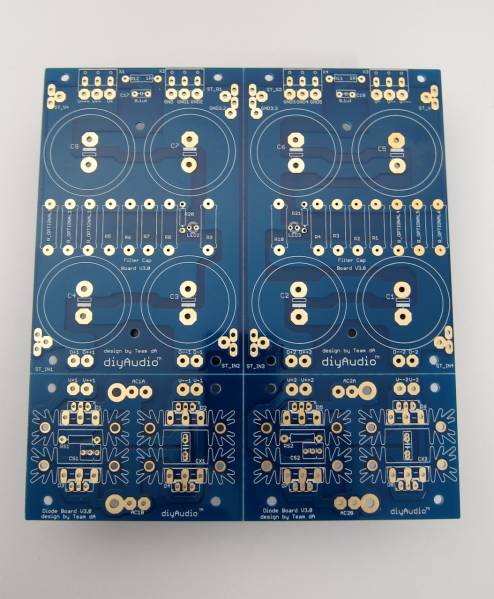
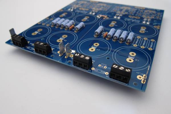
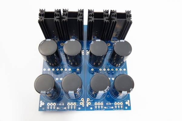
diyAudio Power Supply Circuit Board v3 illustrated build guide

diyAudio Universal Power Supply Circuit Board v3 illustrated build guide. (October 2013)

(Any photo with a link directly below will go to full-size file of the photo)

This build guide will show a typical use of the diyAudio PSU v3 circuit board. This specific build will be suitable for any of the Pass/Firstwatt amps that use a +/-25V supply. If you need a higher voltage make sure you use capacitors of a suitable voltage rating for your project. You may always have a higher voltage rating, but do not use a cap with a lower voltage rating than your rails.

Useful Links

BOM - https://www.diyaudio.com/forums/images/diy/store/board-documentation/P-PSU-1V30/P-PSU-1V30-bom.xls
Schematic - https://www.diyaudio.com/forums/ima...mentation/P-PSU-1V30/P-PSU-1V30-schematic.pdf

PSU18.jpg

PSU18 - My Photo Gallery


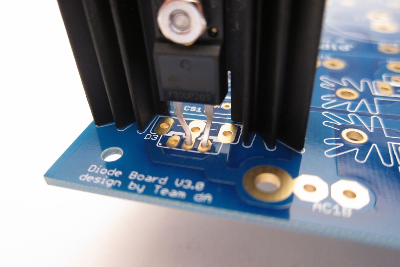
((Do not connect 2-leg TO-220 diodes as shown. See photos in 'heatsink' section.))
PSU36 - My Photo Gallery
Fully stuffed


PSU21.jpg

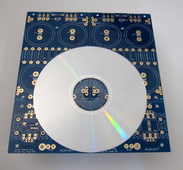
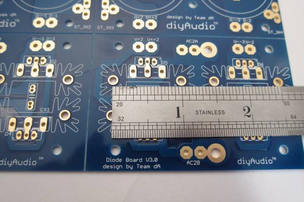
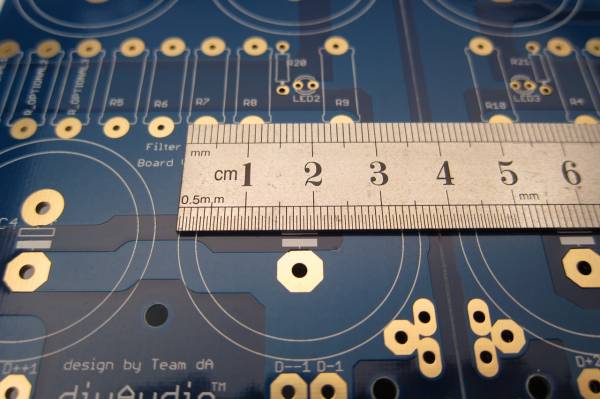
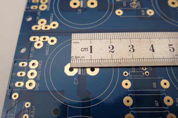
PCB scale

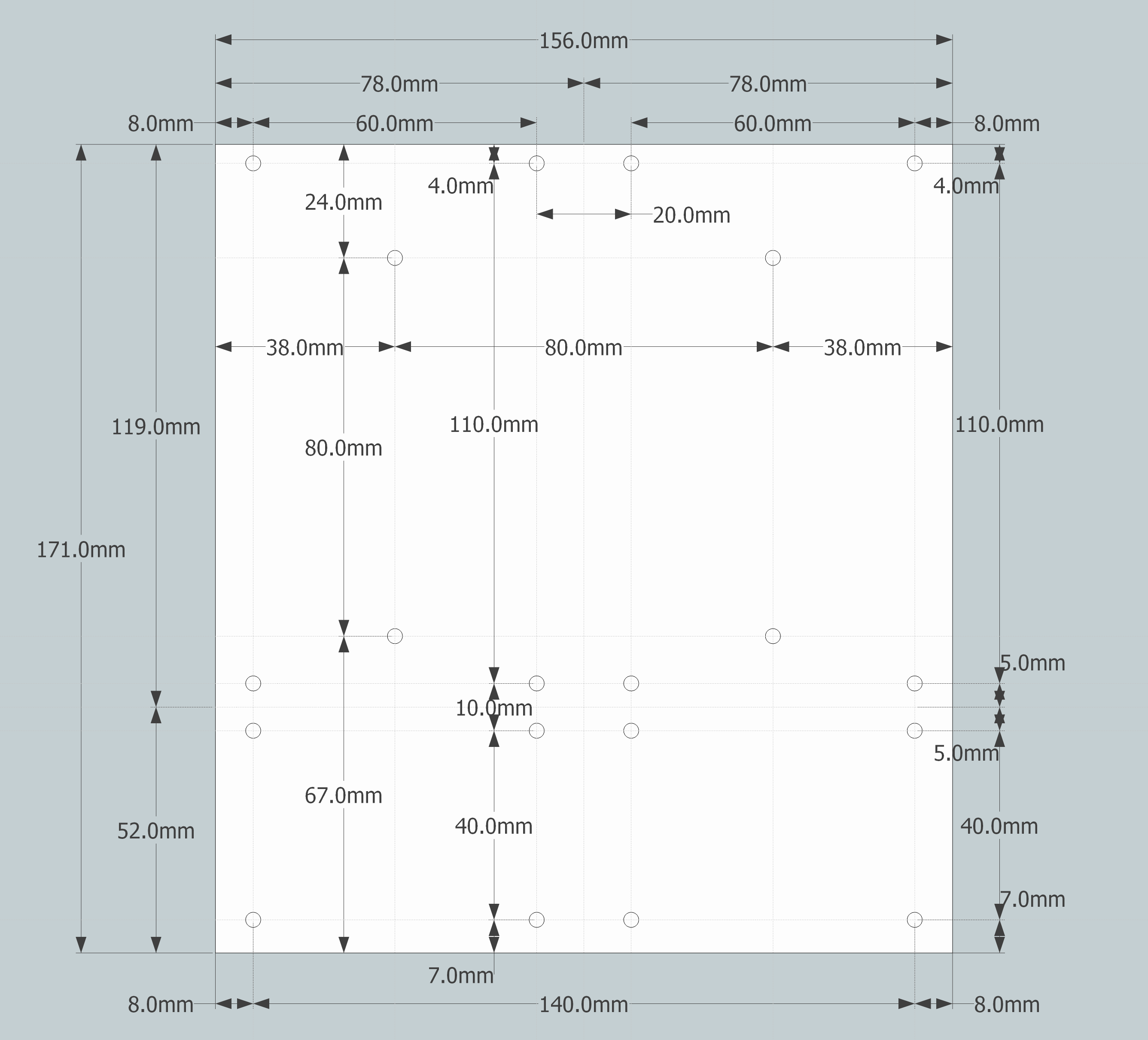
Dimensions -

P-PSU-1V30-dimensions.png

PCB dimensions

P-PSU-1V30-schematic.pdf


PSU14.jpg

PSU14 - My Photo Gallery
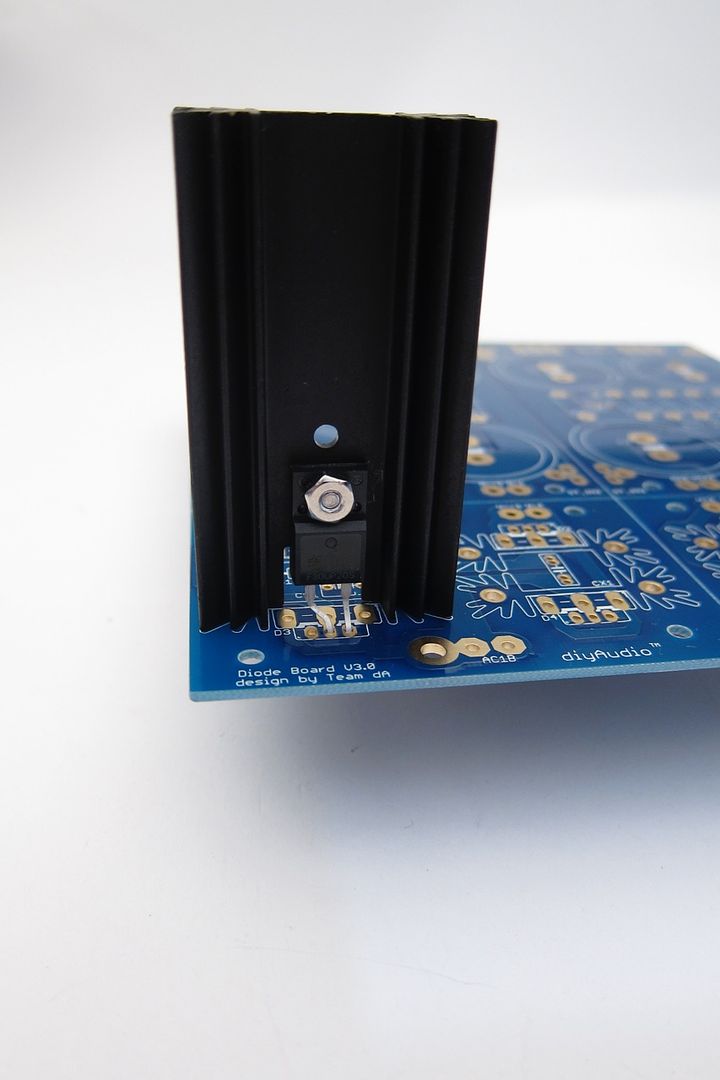
The heatsinks are one inch post spacing. Look at the BOM for a specific part suggestion and find something similar that you can use. The sinks I used in this guide are of the same outer profile, so they fit the pads perfectly, but are quite a bit taller. A number of parts will be available that will work.

IMG_2134.jpg

IMG_2134 - My Photo Gallery
This board can accept capacitors of up to 35mm diameter.

IMG_2136.jpg


Equally important is the lead spacing - the caps should be 10mm 'snap in'. 10mm radial leads will work as well, but usually the bigger diameter caps have the 'snap in' leads.

For more information on dimensions of the specific parts, please consult the BOM for suggested parts, and cross-reference from that part's datasheet. http://www.diyaudio.com/forums/images/diy/store/board-documentation/P-PSU-1V30/P-PSU-1V30-bom.xls

Board features -


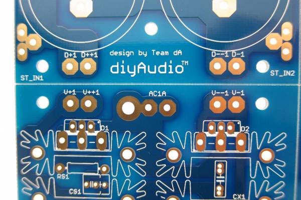
The bridge diode section of the board can utilize either TO-247/TO-3P (larger) package devices or TO-220 (smaller). If heat dissipation / heatsinking is not an issue, you could also use conventional axial-leaded diodes. (Not shown.)


IMG_2135 - My Photo Gallery
If you would like to use snubbers on the rectifier diodes you will find that there is room for them on the top of the PCB, and inside the heatsinks.


IMG_2141 - My Photo Gallery
If you don't find enough room there, or would like to try a different snubber layout, there is plenty of place to connect on the bottom of the PCB, as you will always have one of the d=sets of diode pads empty - you can only use one type of diode at a time, for example if you are using the TO-220, the TO-247 pads will be empty and you may make connections there.


IMG_2142 - My Photo Gallery
For designs that require one, there is also room for a snubber on the output. (Per rail)

Also worth noting, in this photo you can see the multiple solder pads for the output - the row towards the edge is for the euroblock connectors, and the inner row, with the larger pads, for wire. There is also a place for a blade terminal. (Near the board edge, on the outside. To be better illustrated in a later photo.)


Building / Stuffing


PSU41.jpg

PSU41 - My Photo Gallery
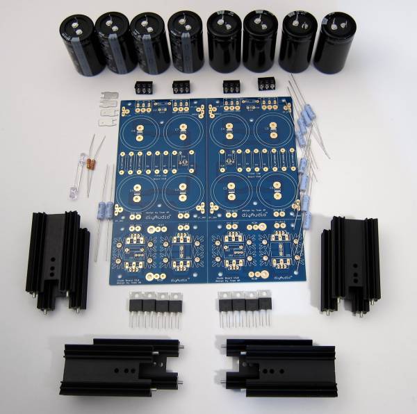
This photo shows all the parts that will be used in this guide.
Starting at top and circling clockwise -
Capacitors and 'euroblock' connectors
(8) filter or 'pi' resistors
Diode heatsinks and diodes (TO-220 package shown)
(2) bleeder resistors
LED and LED resistors
AMP terminal blades

As this board has the scoring to let you separate it if you so choose, you need to notice that there is no connection from the diodes to the first capacitors nor across GND. These must be connected.
PSU19.jpg

The PCB has no connection from diodes to capacitor.

PSU20.jpg

The PCB also has no connection to make GND.

Since I am planning on keeping this PCB intact for the amp I am building, I need to make a connection form the diodes to the capacitor bank, and a connection to establish ground.

PSU24.jpg

You can see all the links here (diode links not soldered in this photo)

PSU211.jpg

GND links. The pads on most of this PCB are all through-plated and big enough to solder from the top if you choose.


PSU28 - My Photo Gallery
In general stuffing should be from the smaller devices to the bigger devices, so the resistors and such should be first. The filter resistors are on the outside, then the LED and LED resistors (the small brown one) and inboard are the bleeder resistors.
The silkscreen markings at the LED pads are slightly obscured, and the break in the circle, indicating where the flat of the LED should go (cathode, negative, short leg) is a little bit confusing. The legs of the LED go as shown. You can also see another link at the top of the PCB where I joined GND together.

PSU26.jpg

The blades are actually taller than the euroblocks, so don't solder them first!


PSU27.jpg

PSU27 - My Photo Gallery
The output edge shown with all the connectors in place

Capacitors -


As mentioned before, this PCB can accept caps with 10mm lead spacing and up to 35mm diameter. This photo shows 35mm caps next to 30mm. You will also commonly find some appropriate values in 25mm diameter.

PSU32.jpg

PSU32 - My Photo Gallery
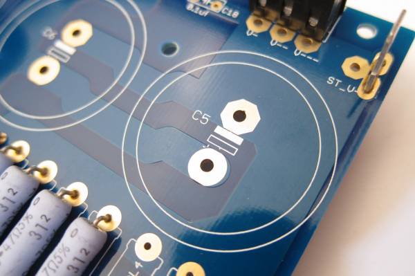
The addition of the large solder pads has obscured the markings on the PCB and the ' + ' mark is somewhat hard to make out. In each case the Positive side is marked with the open rectangle and the negative the white or filled-in rectangle. Remember that electrolytic capacitors are usually only marked on the Negative side.

PSU9.jpg

PSU9 - My Photo Gallery
Note capacitor direction - you can see the negative markings on each capacitor.

Heatsinks -

IMG_2178_zps9f0fe112.jpg


IMG_2177_zps3b3cb4a7.jpg


The heatsinks used in this guide were chosen as they were of proper dimension to fit the PCB, and in-stock at the time I ordered them. They are a little tall, but as Nelson Pass says, there is no such thing as too much heatsink… I do suggest you try to get something that will fit a TO-247/TO-3P package as it will also mount the TO-220, whereas the slightly narrower inner profile of this heatsink will only mount the smaller diode. Regardless, it's quite easy to get really nice, suitable diodes in whichever package - you want 20A, 200V minimum diodes.

PSU30.jpg

A little grease is helpful on the full-pack devices. Secure to the heatsink with a nut and screw. This is a 4-40 screw, about the same size as M3.

Please Read - If you use a conventional TO-220 diode or TO-247/TO-3P it's a very good idea to use an insulator between the device and the heatsink. But it's not necessary - although if you choose not to the heatsinks will probably be live. The heatsinks themselves solder to the PCB and are in holes that have no electrical connection, and aluminum anodize is actually not very conductive, but I would still suggest using an insulator. (Or a full-pack TO-220)


IMG_2182.jpg

Feel free to snap off the diode section and use bridges. They work and sound great!

NOTE - I strongly suggest not separating the capacitor board if at all possible. With it intact, you can run multiple jumpers (as shown) to tie GND together and have a low-impedance, and therefore quiet GND. Splitting it will complicate making a quiet circuit. FYI.

IMG_2180.jpg

Example wiring.
New Builder Looking for Crossover Design Help: 2 Way Bookshelf

I am looking for advice with crossover design. I am attempting to rebuild a set of Cerwin-Vega! L7 Bookshelf speakers. I have decided to use the following drivers:

Visaton SC5-8 Shielded 1/2" Polycarbonate Tweeter 8 Ohm.

Tang Band W5-2143 5" Paper Cone Full Range Driver 8 Ohm.

The enclosure volume is 0.44 cubic feet or 12.4 liters. I am reusing the existing port (1.69” x5" cut down to 3"). I am stuck with the 0.44 cubic feet as I don’t want to cut open the boxes.

I have been experimenting with Xsim for designing the crossover but have a couple concerns, mainly around the impedance curves. I am not sure what is going with the impedance curve for the Tang Band W5 driver, it has a massive spike at around 54 ohms. Nothing seems to smooth it out and I am wondering it this has any potential ramifications to harm my amp or the speaker itself.

Andy help would be greatly appreciated. I have attached a couple images from Xsim.

Attachments

  • Xsim-crossoverImage.jpg
    Xsim-crossoverImage.jpg
    17.6 KB · Views: 84
  • Xsim-crossoverImage-Freq.jpg
    Xsim-crossoverImage-Freq.jpg
    82.8 KB · Views: 82
  • Xsim-crossoverImage-Imp2.jpg
    Xsim-crossoverImage-Imp2.jpg
    88.7 KB · Views: 85

Building a TRS to 2x XLR adapter cable

Hello all.

I am planning on using an unbalanced 1/4” TRS output to send stereo line level to a balanced stereo amp with XLR inputs.

The cable will be Canare L-4E6S. In the middle of the cable I’d like to use a small box to do the actual splitting (i.e. 1 in, 2 out). Should this box be non-conductive, or metallic? If the latter, to which ground/shield should I bond it?

Sunfire Amplifier Fuse holder replacement

Hello, I have sunfire tga-7401 amplifier. The amp has three fuces. Two for current sources and one for ac line fuse. Unfortunately one of the fuce holder is broken and I couldn't find the replacement. Without the fuse holder, fuse does not stay in. Any advice would be greatly appreciated. I have attached the pictures of fuse holder and amplifier.

Attachments

  • PXL_20240405_152214187.jpg
    PXL_20240405_152214187.jpg
    750.3 KB · Views: 27
  • PXL_20240405_164047852.MP.jpg
    PXL_20240405_164047852.MP.jpg
    820.3 KB · Views: 27
  • PXL_20240405_164024412.MP.jpg
    PXL_20240405_164024412.MP.jpg
    796.7 KB · Views: 27
  • PXL_20240405_163507268.MP.jpg
    PXL_20240405_163507268.MP.jpg
    566 KB · Views: 31
  • PXL_20240405_164056834.jpg
    PXL_20240405_164056834.jpg
    789.6 KB · Views: 27

Having fun with JFET buffer and ChatGPT...

Hi,

With the help of ChatGPT I was trying to build the minimal JFET buffer.
The requirement for the buffer is to take high impedance preamp output and help to drive low impedance next stage.

So, ChatGPT has suggested the following circuit, claiming «the buffer will effectively isolate the preamp from the lower impedance load that follows».

1710975940625.png


I am not a real electrical engineer and the circuit kinda makes sense to me. I have tried to assemble it and I get completely no sound at the output. JFET doesn't seem to conduct any signal. I have tried it with J201 and with MPF102, no luck with both.

It is simple enough and I seem to have checked everything multiple times. And ChatGPT keeps insisting it should work and I am stupid.
Could somebody give me a hint? Is it a viable circuit? What is missing for it to work as intended?

Thanks.

2-way MEH with Celestion H1-9040P

I'm in the planning phase of a 2 way MEH with the Celestion H1-9040 horn. I have the H1-9040 and it looks feasible to add either 1 or 2, 3-4 inch midrange drivers on the top or bottom of the horn.

This will be my second MEH so I'm familiar with Hornresp. What I'm not familiar with is the exponential horn. Horn flare at the beginning (1" CD driver opening) is slow to expand. This appears to allow the mid range opening at S2 to be less dependent on close location to the CD driver opening?

I only had a few hours to play with HR last night so I don't have any graphs to post.

Anyone else try messing with MEH plus exponential horn who can offer advice?

John

Pioneer SX450 BUZZ

Hi all.
I´d like to get some help from you, if you could look at this.
A few years ago I bought this amp.
I replaced nearly all of the transistors+output transistors, diodes in power supply (except the 2 pieces of Zener diodes ), all the caps (except the one at MIC input),
many tantalum caps (except the TT and TUNER board).I cleaned all the switches and pots.
I measured resistance between grounding points and the chassis, everything seems OK.
I re-soldered everything again.
But still is some slight buzzing noise comming from the right channel (under the transformer), but the left channel is much better.
This buzz is there even when the volume pot is all the way down.
If I put some metal plate under the winding of the transformer, hum is gone but the buzz is still there.
I am sure, it is some bad grounding somewhere.
Idle current : 15 mV both channels
DC offset: R: 20mV. L: 2mV

The low noise level is still the same.
Could you help me please to find the reason?
Thank you very much.
Jan.

Attachments

  • P1010679.JPG
    P1010679.JPG
    246.8 KB · Views: 51
  • P1010680.JPG
    P1010680.JPG
    242.9 KB · Views: 44
  • P1010681.JPG
    P1010681.JPG
    240.9 KB · Views: 35
  • P1010682.JPG
    P1010682.JPG
    240.4 KB · Views: 40
  • P1010683.JPG
    P1010683.JPG
    230.8 KB · Views: 50

Angling for 90° - tangential pivot tonearms

There has to be a way to get that 90 degrees on a stylus without the damn air pump!!


I don't want to go off track in other tonearm threads so I decided to start a new thread focusing on the discussion and design ideas for pivot style tonearms that can attain tangential tracking, a pivot linear tracker if you will. Sounds like an oxymoron but it can be done.

To be brief, most tangential tracking tonearms are typically air-bearing tonearms that allows the stylus glide across the radius in almost frictionless manner to simulate how a record is cut on a lathe. Other means of this gliding action can be also achieve via linear bearings like rollers on a rod or bushing on a rod, etc... Some concept arms even suggest using floating opposing magnets. The flaw of such tonearm is that the horizontal mass is enormous regardless of bearing quality, low friction or no friction. It limits the choices of stylus, depending on its compliance. And the use of an air pump is not for everyone to say the least - a personal pet peeve of mine. The genre of electronic servo detection pseudo-tangential trackers like the Rabco tracking across the record in tiny little arcs constantly self correcting its way to the end of the record is not part of this discussion here. Anyway, this thread is NOT about the above tonearms. We want to talk about pivot tonearms that can track tangentially by changing stylus angle simultaneously.

The best examples are actually currently available in production. By now, many people have heard of the Thales tonearm from Switzerland. It is a pivot style tonearm with an extra pivot at the headshell area right above the stylus. The changing angle is always 90 degree to the radius because it is part of a triangle that is inside a semi-circle that adheres to the Thales theorem, that is, "Thales discovered that the circumferential angle subtended by a triangle in a semicircle is always a right angle. As a result, the half circle above the hypotenuse of a right-angled triangle is called the Thales Circle."

http://www.tonarm.ch/kommentare/thaleskreis_e.html

6moons industryfeatures: Thales

.

An externally hosted image should be here but it was not working when we last tested it.


.

With the basis of the Thales Circle, the designer Micha Huber devised a tonearm that can track any point inside the semi-circle always 90 degrees to the center of the record, voila a linear tracking tonearm that pivots without any linear motion. Genius! The tonearm appears to be executed with quality construction and precise worthy of a Swiss watch. So far it is the ONLY tonearm on the market that is capable of 100% geometric accuracy in maintaining tangency, at a price,of course, as it sells for, I believe, 6000 €.

.

An externally hosted image should be here but it was not working when we last tested it.


.

Visually, it has the look of a Rube Goldberg device but looking closely, everything seems to have its specific function for good reason. I don't want to write a white paper on the Thales design but for those who are interested in examining it more closely, feel free to explore its website. But this tonearm does give a good example of the objective here.

.

Thales will introduce a new tonearm named "Simplicity" that looks simpler and elegant and even though it is not 100% accurate in geometry but it reduces the tracking error to a maximum of 0.008°! Pretty damn good in my book.

.

An externally hosted image should be here but it was not working when we last tested it.


.

There are historical predecessors of such design and one can find that in the classic Garrard Zero 100.

.

DSC05205.jpg


.

tonearm.gif


.

And the Burne-Jones arms.

.

An externally hosted image should be here but it was not working when we last tested it.


.

BJ_Super_90_Tangential_Tonearm_for_sale_collage.jpg


.

One can also find examples in contemporary designs like the RS Labs RS-A1 arm with a pivoting headshell.

.

Shilabe%2BMiyajima%2Bcart%2Band%2BKimura%2BRS-1A%2Barm%2B002.jpg


.

Shilabe%2BMiyajima%2Bcart%2Band%2BKimura%2BRS-1A%2Barm%2B008.jpg


.

"Prototype of the 'Bajulaz' tonearm on a TD-124. It was designed by Ing. Bajulaz to overcome the geometry problems of the conventional tonearms, but allegedly it wasn't so good for the new stereo cartridges and therefore never went in production."

.

An externally hosted image should be here but it was not working when we last tested it.


.

I will continue to upload more pictures and present ideas to stimulate discussions and, hopefully, inspire the DIY spirit.


.

Tubes for sale (841, 814, GM70 & Aa)

I have a few tubes for sale. Each pair sold separately, or discounted as a bulk sale.

2 tubes each below

GE vt-52 / 841. (pair $425)
Philips 814 (pair $325)
GM70 Russian Graphite Plate (pair $250)
Valvo Aa ($299)

Reasonable offers accepted.

All tubes are NOS. 5-day money back guarantee (less shipping).

Happy to provide photos upon request.

Thanks!
Pat
banpuku@mac.com

6P3S-E push pull amp build log

Hello felllow audio DIY-ers!
I'm just starting to build a 25 year old project...a stereo push pull tube amplifier I "started" to build when I was in highschool...but never got to finish....I guess it's about time :)
Back then there was no chance to get a good output transformer...for me anyway..and the internet was not what it is today...some had dialup I didn't...so I gathered the chunkiest transformers I could find planning to open them up and rewind them, all local magazines with tube amplifier articles...found old electronic engineers in my town to source schematics datasheets and..the tubes of course. Things stopped when I tried to open up and rewind the output transformers ...good luck with that!..and highschool finished priorities changed...
I the meantime I occasionally "light up" about tube amps or other things while browsing the internet so at some point I purchased toroidal output transformers, all components for a linear regulator and an old grundig tv set transformer
So having basically all components sitting for the amplifier...I got this "urge" a few days ago to build it and I started putting together a chassis with all the components.
I don't know what's gotten into me I'm not even into tube amps anymore...or am I? I find myself salivating when I see nice tube amps or full boxes of interesting NOS tubes and wish to have them :)
I'll post some pictures and later I'll have some questions for sure...

Depinning an audio connector... tools and parts?

Hi all, I have this 8-pin audio connector for my Alpine amplifier. The yellow power cable wiggled loose from its pin, and I have been unable to remove the pin from the connector, despite my best efforts filing paperclip ends into a flat profile to make a depinning tool.

How can I remove the pin, and where could I order new pins (or reuse this one) ? Thanks!

I am located in the UK. Thanks!

Attachments

  • PXL_20240406_113538088.jpg
    PXL_20240406_113538088.jpg
    225.9 KB · Views: 27
  • PXL_20240406_114115529.jpg
    PXL_20240406_114115529.jpg
    162.9 KB · Views: 21
  • PXL_20240406_140608400.jpg
    PXL_20240406_140608400.jpg
    329.1 KB · Views: 26

4PDT Switch question

This is possibly self-answering, but I‘m looking for confirmation:

4PDT „ON-ON“ is the same as
4PDT „ON-NONE-ON“?

https://eu.mouser.com/ProductDetail/NKK-Switches/M2042SS4W01

https://eu.mouser.com/ProductDetail/NKK-Switches/M2042SS4W03

I‘m asking because I used something that looked liked a „4P3T“ (?) but it had continuity to an outer channel when it was in the center position. Removed it and want to avoid further glitches…

Why don't people build more coaxial systems?

I have the parts together for a quick and dirty 2 way open baffle system. One of the uses I have for them would be as studio monitors and the desk has the center of the 12" bass driver basically at ear level. I would be using a DSP amp so I can mess with delay and other parameters.... but I was thinking about mounting the full range driver coaxially. I don't think I've seen such a setup here outside of pre-made coaxial drivers.... am I missing something?

LM1875 XY board

First post to the forum...

I recently purchased a few of the LM1875 XY boards from Ali Express, but there was no schematic included to compare with the data sheets for the chips, and as a relative newbie to DIY Amplifiers and I am confused by a few items.

I was initially confused by J3, but after a few hrs of research online, I found some photos of a KBL04 bridge rectifier in its place. I was also confused by C1 and C4, as there were numerous holes supplied and it only called for a 1uf capacitor. I have since realized that the extra holes were to be able to choose different sized capacitors perhaps?

Anyway, after scouring some threads, it appears that there are some issues with the power supply being inadequate... So I was wondering if anyone has used these boards to build either a LM1875 or TD 2030/2050 "decent" sounding amplifier, if they wouldn't mind sharing their build ideas or links to threads that I can explore, or any other recommendations before I start soldering... I'm basically just looking to build a decent sounding power amp to power some YAMAHA S115V PA speakers that I had laying around....

Thanks in advance!

XY LM1875 board.png
LM1875.jpg

4 x Peerless SLS-P830668 or 1 x SB34NRXL75-8 for musical sub?

Hello i want to build a music subwoofer ( bass reflex ) with tight articulate bass with good instrument separation and reasonable extension ( 35 hz ) and i can choose 1 x sb acoustics woofer or for the same price 4 x peerless ( sort of like Tekton 4-10 SUB , they will be 2 x 2 driver modules but stacked onto eachother ) . Will the sba be bested by 4 x cheaper drivers ? Are any downsides to using multiple bass drivers with slightly different parameters than one driver ? Looking at dibirama THD measurements the peerless sub starts to distort heavily below 60 hz compared to even SB34NRX75-6 which is worse driver than NRXL-08. Are there any alternative drivers for cheap multiple drivers sub ?

Low Power Balanced Mono-Block Tube Amplifier

I will be posting information about my new design balanced amplifier.
Today, the amplifier schematic, and a picture of the amplifier.

Soon, the power supply schematic, another picture, and my discussion of the design decisions I made.

Later, measurements of the amplifier performance.

Attachments

  • DSC00153.JPG
    DSC00153.JPG
    363.2 KB · Views: 649
  • 6A3-balanced-amp.png
    6A3-balanced-amp.png
    28.4 KB · Views: 375
  • Like
Reactions: 9 users

For Sale R-Theta 65340 heatsinks (4)

Hi,

Member from many years ago returning with some unused goodies to sell.

Took part in the 2003 group buy of the 11x11 R-Theta 65340 heatsinks and never quite got around to building the project. At this stage, it's better that someone else have some enjoyment from them.
1712268947791.png

If you can believe it, one of the boxes had been sealed since 2003. Here's a quick pic of one of heatsinks out of the packaging:
1712269316102.png

I'll sell them all for $240 Canadian plus shipping, on inflation alone they'd sell for $316 now. They are heavy and there are two (original) boxes to be shipped, so I expect the shipping quote to be sizeable.

I'm in Halifax, Nova Scotia, if there is anyone nearby interested. Can provide more pics if necessary.

Thanks for reading, and I hope there is someone out there that can turn these into a decent project.

Robt

Help, cheapish power amp wanted

I am looking for a good sounding power amp for an active system.

To drive a pair of 5" drivers per channel, 8ohm Celestion TF0510MR closed back, wired in parallel.
The drivers have no crossovers hi or lo pass, and operate with acoustic frequency limits / horn loaded through taps in a band pass, between around 325Hz to 954Hz.
What's below that and above that is killed off with EQ.

I've been using a little 5W EL84 SET amp and recently trying a Topping TP-60 (I know😀), just to try.
I wonder if the damping factor of the SET is too low for the drivers. It operates but...
The TP-60 seems to work okay but I want to up the game if possible, within a reasonable budget.

All help gratefully received.

Puzzling Set of Output Transformers

I have a set of potted output transformers, purportedly from a Sansui amplifier/receiver. They were touted by the Ebay seller as transformers compatible with EL84/6BQ5 outputs, which would place them at 8K optimum plate-plate impedance. As I usually do, I scoped out the primary leads (~400 ohms plate-plate, with a tap at 200 ohms - smells like a P-P transformer). I drove the 2 plate leads with a sine source at 50VAC, 300Hz, and got 0.905V out. This has me scratching my hard, as this indicates a turns ratio of 55:1, and a bona-fide 8k transformer would have a turns ratio of 31.6:1, and an output of 1.6 V or so when driven with 50V P-P. The turns ratio indicates 24k load at primary side with 8 ohm load. What were these transformers intended to do? They look good for about 15W apiece from the standpoint of size. Higher voltage input? Lower output impedance.? I hunted around on the secondary taps, and 0.9V or so is the most I can get out of them with 50V plate-plate drive on the primary side. Both transformers measure the same - head-scratching time...

Voice coil rewinding newbie questions

I'm looking to get into voice coil rewinding.
I have a few questions.

Where can I get some supplies?
Like a winder that can count turns?
Those metal cylinders of various sizes you use to build a new coil around? Not sure how to find these because I don't know what to call them.
Material to build the formers out of?
Is there anything I need to be aware of when buying magnet wire, other than gauge?

What do I use to hold the windings together? Epoxy? Varnish? Youtube videos showed epoxy. Slow cure?

I can replace voice coil assemblies and do reconing and refoaming already.

Kenwood KX-50 service manual

Hey guys, I'm inexperienced in the realm of tape decks, walkman, etc. I recently bought a Kenwood KX-50 tape deck. The tape deck turns on, however, it doesn't play anything. So I opened it up and a lot of the belts had melted. The ones which were still intact were very stretched... So I went onto ebay and bought a 'kit', only to later realise upon the arrival of the kit, that the kit only contained 2 belts - I needed all 5...
I see that HifiEngine has the service manual which - I hope - may contain the measurements for the belts. I figured that I could buy some cheap belts from AliExpress which are similar in size to the originals. I just can't find the measurements of the orignals, so my plan is being halted. HifiEngine's registerations seem to be closed as well which I find quite bizarre... I was wondering if there's a kind person out there which can help me get a hold of the measurements or service manual from HifiEngine or any other site which can provide either. I also tried ElectroTanya but to no avail... Thank you very much in advance!

For Sale NAGRA IV-S

I am selling my NAGRA IV-S professional reel to reel broadcast recorder. Offer includes the NAGRA IV-S plus ANT-2 power supply as well as a genuine Nagra leather carrying case/bag.

It is in excellent technical and cosmetic condition, a true collector's item.

Location: Budapest

Asking price: EUR 4.690 + shipping

I am happy to send more photos for serious buyers.

Attachments

  • DSC03632.JPG
    DSC03632.JPG
    431.6 KB · Views: 109
  • DSC03635.JPG
    DSC03635.JPG
    431.8 KB · Views: 105
  • DSC03636.JPG
    DSC03636.JPG
    396.6 KB · Views: 98
  • DSC03648.JPG
    DSC03648.JPG
    428.3 KB · Views: 96
  • DSC03649.JPG
    DSC03649.JPG
    371.9 KB · Views: 93
  • DSC03730.JPG
    DSC03730.JPG
    417.1 KB · Views: 90
  • DSC03735.JPG
    DSC03735.JPG
    496.3 KB · Views: 96

For Sale Lyra Dorian

I am selling my Lyra Dorian, which has been checked and updated with a new boron cantilever and Micro Ridge stylus by Ana Mighty Sound. Since the retip it has been only used 10-20 hours.

Frequency range : 10Hz - 50kHz
Cantilever system : Boron rod cantilever, natural diamond, Namiki MicroRidge line-contact stylus (2.5 x 75 micrometers profile)
Channel separation : 30dB or better at 1kHz
Internal impedance : 9.5 ohms
Output voltage : 0.6mV (5.0cm/sec., zero to peak, 45 degrees)
Cartridge weight (without stylus cover) : 6.4g
Compliance : Approx. 12 x 10-6 cm/dyne at 100Hz
Centerline through mounting holes to stylus tip : 9.5 mm
Recommended tracking force : 1.8 - 2.0g
Recommended impedance : 100 ohms to 47 kohms

Tracking ability: 80 micron / 315 Hz / lateral / 18mN

Location: Budapest
Asking price: EUR 790 + shipping

I can pack it very safe, I shipped many cartridges in the past.

Attachments

  • DSC03376.JPG
    DSC03376.JPG
    276.9 KB · Views: 71
  • DSC03377.JPG
    DSC03377.JPG
    238.3 KB · Views: 66
  • DSC03380.JPG
    DSC03380.JPG
    234.6 KB · Views: 71
  • DSC03382.JPG
    DSC03382.JPG
    236.9 KB · Views: 66
  • DSC03461.JPG
    DSC03461.JPG
    526.5 KB · Views: 69
  • DSC03464.JPG
    DSC03464.JPG
    304 KB · Views: 67
  • Like
Reactions: 1 user

For Sale Shinon Red Ruby

Condition: used, but with new silicone damper in excellent condition and low playback hours. Silicone damper has been installed by Ana Mighty Sound.

Specifications
Stylus: Shibata
Cantilever: Ruby
Colis: copper
Coil imp.: 6,5 Ohms/ch/DC
Tracking ability: 70 micron / 315 Hz / lateral / 21mN

(Tested in an IKEDA IT-407 tonearm with DIN 45549 test record.)

Location: Budapest
Asking price: EUR 1390 + shipping

Attachments

  • DSC02506.JPG
    DSC02506.JPG
    112.3 KB · Views: 51
  • DSC02515.JPG
    DSC02515.JPG
    110.9 KB · Views: 50
  • DSC02841.JPG
    DSC02841.JPG
    262.6 KB · Views: 51
  • DSC02849.JPG
    DSC02849.JPG
    293.6 KB · Views: 55
  • DSC02850.JPG
    DSC02850.JPG
    238.7 KB · Views: 59
  • DSC02853.JPG
    DSC02853.JPG
    131.6 KB · Views: 57
  • DSC02514.JPG
    DSC02514.JPG
    132.4 KB · Views: 51

For Sale Roksan Shiraz

Condition: used, in excellent condition and very low playback hours. New silicone damper has been installed by Ana Mighty Sound.

Tested in an IKEDA IT-407 tonearm with DIN 45549 test record.
Tracking ability: 120 micron / 315 Hz / lateral / 22mN.

Specifications:
Type : Moving coil
Output: 0.21 mV/cm/sec (RMS), 1.05 mV @ 5cm/sec recorded velocity
Stylus: Super fine line - F. Gyger II ( 6 x 40 micron ) nude diamond
Cantilever: Aluminium Tube
Tracking weight: 2.2 -2.5 (2.4 grams recommended)
Cartridge body: 5 axis machined solid aluminium alloy
Generator fixing: Unique 3- point rigid fixing, spiked to body (without adhesive)
Cartridge fixing : Standard 0.5 inch centres (12.7mm)
Recommended load: 30-1000Ω (100Ω recommended)
Coil impedance: 24Ω
Frequency response: 5Hz - 30kHz
Channel balance: Within 1dB
Channel separation: 0dB/ 1 kHz
F I M: < 0.5%, 19μ
Cartridge weight: 8.2 g

Location: Budapest
Asking price: EUR 1800 + shipping

Attachments

  • DSC02373.JPG
    DSC02373.JPG
    174.2 KB · Views: 51
  • DSC02375.JPG
    DSC02375.JPG
    311.4 KB · Views: 52
  • DSC02382.JPG
    DSC02382.JPG
    92.9 KB · Views: 46
  • DSC02383.JPG
    DSC02383.JPG
    43.4 KB · Views: 51
  • DSC02385.JPG
    DSC02385.JPG
    199.3 KB · Views: 47
  • DSC02389.JPG
    DSC02389.JPG
    271.9 KB · Views: 48

For Sale Ortofon Rohmann

Condition: used, but in very good technical and comsetic condition, with low usage hours.
It has been checked by Ana Mighty Sound.

Tested in SME V tonearm with DIN 45549 test record.
Tracking ability: 80 micron / 315 Hz / lateral / 25mN.


More information about the cartridge can be found here: http://ortofon.com/hifi/products/historical-products/mc-rohmann

Location: Budapest
Asking price: EUR 800 + shipping

Attachments

  • DSC03464.JPG
    DSC03464.JPG
    304 KB · Views: 57
  • DSC03467.JPG
    DSC03467.JPG
    373.8 KB · Views: 48
  • DSC03468.JPG
    DSC03468.JPG
    209.7 KB · Views: 49
  • DSC03471.JPG
    DSC03471.JPG
    166.7 KB · Views: 52
  • DSC03489.JPG
    DSC03489.JPG
    44.3 KB · Views: 50

PSU Schematic advice needed for 6SN7 line stage preamp

Hello friends,

Many years in ago, in 2006, I built this 6SN7 preamp. I sourced the schematic from the late Wim Bouwman (Mr Valve) in South Africa. I used the preamp with a solid state power amplifier, and it sounded really good. The gain was somewhat high though.

I have lost my notes on the project, and cannot seem to find satisfying info on a simple yet effective power supply design for this build.

Below is are pictures of the schematic.

Could any of you tube aficionados point me in the right direction? It would be much appreciated.

Thank you in advance,
Christian


6sn7 schematic Mr Valve.jpg

5.1 input Sony MHC GN88D

I want to connect 5.1 audio to sony gn88d from my pc.But sony gn88d does not have 5.1 channel aux input.On its main board,There is an FPC connector named FR,FL,SL,SR,C,SW etc.

I connected phone audio there.Audio is not clear and broken audio. In schematics PCM1609KPTR (Digital to analog converter ic)> circuit ( filter or something)>M61530FP-D60G(surround volume control).


When I connect phone audio to the circuit(filter ?) before the surround volume controller ic, the audio is clear but 90% volume is decrease.

Any solution?

Or

Is it possible to convert the phone audio signal with the same characteristics analog audio coming from the PCM1609 ic?


Sorry my English is bad.

Attachments

  • hcdgn88d (1)(1).pdf
    8.4 MB · Views: 35
  • IMG_20240406_165207.jpg
    IMG_20240406_165207.jpg
    273.7 KB · Views: 27
  • _storage_emulated_0_Android_data_com.adobe.reader_files_Pictures_Adobe Acrobat Exports_hcdgn88...jpg
    _storage_emulated_0_Android_data_com.adobe.reader_files_Pictures_Adobe Acrobat Exports_hcdgn88...jpg
    257.3 KB · Views: 23
  • pcm.jpg
    pcm.jpg
    191.8 KB · Views: 25

Using different class amps for a better top end

I recently did a test running one of my class D PA amps against my hifi (cambridge audio azure power amp). This was done through my hifi speakers (focal aria 926). PA amp drove the left speaker whilst the cambridge drove the right. When sat at a distance with not great room acoustics it sounded like the same amplifier driving both speakers. But putting your head right next to the drivers and moving going back and forth between the left and right speaker there was a noticeable difference. The cambridge amp just had greater high end detail and better separation of the midrange elements. Id say the difference was comparable to testing a 500 quid integrated hifi amp versus my a mid / higher end power amp.
It got me thinking that maybe for my PA system I could move away from the high power class D amps for the top end (dual diaphram coaxial compression drivers - 700hz up) and perhaps go with a much lower powered class AB amp instead. I believe these are inherrently much cleaner at the top end than class D. I'd need a 2 channel amp per driver / stack and ideally with the ability to set rms / peak limiters via DSP.
There was one unit I found which does seem to fit the bill, the QSC XTi 1002. Has all the attributes and isnt too expensive per unit, but the question is would I be wasting my time even obtaining and trying this amp. Will it actually have a cleaner top end more on par with my hifi power amp? Or should I just get saving and go with a higher end class D amp instead ( powersoft, mc2, linear research etc). Any thoughts appreciated.

Linear PSU for NA ATX PC

Hi, I have a Home Theater PC that I use to feed my DAC from the USB. To get a better signal, I have a SoTM pci to USB card. For the streaming Imhave etither JRiver or Roon. My question is I know that a PC is a very noisy environnement. Does anyone know a way to at least replace the PSU and put a linear PSU for ATX. In my research, I have found the Teradak system but it’s way over priced. More then $2k just for a power supply. Or am I better go to a NUC pc and add a good linear psu. In this case I won’t be able to use my SoTM USB card…

thanks

CKT-TF1525e System build

I'm about to start making a pair of celestion TF1525e speaker boxes (https://celestion.com/wp-content/uploads/2019/10/188.pdf) and was wondering if anyone had attempted making these before and had any specific tips on making them, or if anyone had more general advice on speaker cab construction.

For the panels, I'm going to get them cut on a cnc machine to keep the edges nice and straight. I'm either going to use the recommended 15mm birch plywood, or an alternative to birch as its quite expensive at the moment. To secure the panels together I was thinking of using wood glue and countersunk screws to increase the grip between the panels (is this nesacery or will just standard brad nails work instead?). I'm going to leave the finish as exposed wood instead of painting so will need to apply some hard wearing varnish on them so that they don't get banged up as easily. I might look to make some stands for them as well as this is the recommend positioning for them (but I might also jsut use them on a table depends how lazy I'm feeling).

For making the crossover I'm going to use the plan shown on the link above, although one part of it has confused me a little. On the design C1 and C2 are shown next to each other but with a "/" in between. Does this mean that the values are interchangeable or will I need two capacitors for the low pass filter? Also on the diagram for C2 the value is in uH instead of uF, I'm guessing this is just a typo though and I'm just going to use a uF value instead. For the inductors I haven't really been able to find ones of the exact values so I may have to buy some larger ones and uncoil them to get the right value, does anyone have any experience of doing this and know how to get the best results? I've also drafted up a components list of what I'll need for the crossover:
LF:
L1: https://www.bluearan.co.uk/index.php?id=CNVACLD180 - potentially use a core from willys hifi -https://willys-hifi.com/
C1: https://willys-hifi.com/products/mkp-polypropylene-hifi-crossover-capacitor-10uf-250v
C2: https://willys-hifi.com/products/mkp-polypropylene-hifi-crossover-capacitor-2-2uf-250v
R1: https://uk.farnell.com/arcol/hs25-1r-j/resistor-wirewound-1ohm-5-axial/dp/2478173?st=1ohm resistor - more on https://willys-hifi.com/collections/resistors-20-watt

HF:
L2: https://www.bluearan.co.uk/index.php?id=CNVACMC072 - will need to uncoil to give desired value - potentially use a core from willys hifi -https://willys-hifi.com/
R2: 12 Ohm 20 Watt 5% Ceramic Wirewound Resistor - Willys-Hifi Ltd - more on https://willys-hifi.com/collections/resistors-20-watt
R3: Jantzen Superes 10W 100 Ohm 1% Crossover Resistor - Willys-Hifi Ltd - more on https://willys-hifi.com/collections/resistors-20-watt
C3: https://willys-hifi.com/collections...lypropylene-hifi-crossover-capacitor-1uf-250v
C4: https://willys-hifi.com/collections...propylene-hifi-crossover-capacitor-6-8uf-250v
P1: https://cpc.farnell.com/raychem-te-...-radial-1-35a/dp/FF02433?ost=1.35a+polyswitch

Please refer to the link at the top if the component acronyms don't make any sense.


I think this post covers my basic prebuild understanding of the design and how I will execute the build, if anyone has any tips to add or things that I should be considering which I haven't mentioned then please let me know. Otherwise just wait for more posts to show progress updates on the build!

Sanyo/B&O Icepower 200AC Rev.D, schematic about rev. engin., not complete finished

Sanyo/B&O Icepower 200AC Rev.D, schematic about rev. engin., not complete finished

some time ago I had make trobleshooting and repair by a ICEPOWER module from B&O. Therefore I must create a schematic, that was not available by the manufacturer. But the schematic was difficult to reconstuct, because the PCB use multilayer technology. So any connections are not to see and some other are unknown, where do they go (at whole four or five wires - I think).

Nevertheless this schematic could be of interest for one or the other.

Perhaps one of the members this can complete.
  • Like
Reactions: 1 user

Micromega Duo CD3.1 schematic?

hi,

does anyone have a schematic for a micromega duo cd3.1?
the power transformer has died and i need to know the rating/voltages so i can get some kind of replacement.

it started to hum, then over time developed a slight buzz until it started really vibrate almost like a mobile on silent, then it suddenly stopped and then i noticed the player was off. tried the fuse, cable and then i opened up the cd player and could see that the top of the transformer has gone a brown colour like it was giving off loads of heat

how does this kind of thing happen? am i right to think that with age and heat that it has somehow 'de-laminated' itself which caused it to vibrate? the micromega has a circuit which is always powered up unless you unplug it, mabey thats why it died?

i have searched the web and found what i think are suitable replacements but without knowing the specs im stuck.

any info would be much appreciated
thanks

FH9HVX - Budget Conscious 100w Class AB for Lean Times

Edit June 5, 2020: Here is my completed FH9HVX in dual mono using a cast iron griddle heatsink:
848644d1590823434-fh9hvx-budget-conscious-100w-class-ab-lean-times-griddle-fh9hvx-mosfets-setup-closeup2-09-jpg


849180d1591003996-cast-iron-griddle-amp-budget-conscious-heatsink-solution-griddle-amp-final-02-jpg

More info on the Griddle Amp here.

There was a very nice little Class AB amplifier I worked on years ago based off of Apex Audio's wonderful little FX-8 lateral FET amp. Back then I did not want to use the lateral FETs because they were pricey. So I set off to make a hexFET based version. It was called the FH9, and it sounded very good. If one used generic resistors and caps, you could build the whole amp for under $10. The layout was done by several people, Sonal K and Prasi, but the one that caught on was the Sonal K layout.
Here was the Sonal K layout:
838214d1587945663-fh9hvx-budget-conscious-100w-class-ab-lean-times-fh9-sonal-jpg


Many people have built this amp since then and it has been a favorite. At one point, I swapped out the transistors for some high voltage ones and hooked it up to a $20 Abletec +/52v SMPS. Running a pair of IRFP240/9240's I was able to eek 150w into 8ohms with it.
558782d1467949449-100w-ultimate-fidelity-amplifier-fh9-hv-heatsink.png


That's 34.5Vrms into fan cooled 8ohm load:
558783d1467949449-100w-ultimate-fidelity-amplifier-fh9-hv-stress-test.png


Over the years, I continually get requests for help with this amp or people asking for a PCB etc. I have noticed that lately with the Covid19 quarantine going on, many people are not having as much cash on hand for premium parts. So I thought it might be neat to revisit this amp and see if we can make a nice performing budget 100w amplifier. Naturally, I have enlisted the help of JPS64 to do the layout, and Vunce to help with the beta testing. Vunce has since gotten the original FH9 to work and is about to get stereo sound any minute now. In the meantime, I have put the circuit back on LTspice (it was on Tina in the early days). And I have tweaked it for 52v rails and nominal output up to 100w into 8ohms. No fancy parts and not even four MOSFETs. Just 1 pair per amp if you use Fairchild with a higher power rating, should be fine. No matching to do. The amp is super simple and very pleasant to build in one evening. If you happen to have an old Abletec 225w SMPS, dust it off and you can have one of these amps playing. It has a very powerful bass and nice overall presentation. One of my favorite simple amps to make and listen to. Many people can vouch for its sound if you check on the Apex thread.

On this amp, one can use nice Dale resistors, boutique input coupling caps, or you can use no name Aliexpress resistors - it won't matter. I just ask that you get either genuine Vishay IRFP240/9240 or genuine Fairchild FQA40N25/FQA36P15's (about $7/pair). You can run it at +/-35v of course as a 50w amp, but I suggest going for the +/-52v version and getting it to crank to 100w without a sweat. THD predicted at 100w is only 0.005% and at 25w is less than 0.003%. Dominant second/third order harmonic distortion, and a semi-monotonic descending higher orders (ok, so it's no SE Class A amp in profile...) But what it has is some great bass dynamics, and killer foot tapping immediacy. A very fun amp to listen to and play with. Cheap fun.

If you don't want to go with a cheap +/-52v SMPS, a single 300VA 38v trafo will work nicely or dual 200VA 38v trafos and a simple CRC PSU with four 10,000uF caps each will work fine.

Here is the LTspice schematic (in JPS64 part notation):
838205d1587944992-fh9hvx-budget-conscious-100w-class-ab-lean-times-fh9hvx-schematic-v001-jpg


Here is the LTspice file for the simulation.

Here is the predicted distortion at 25w into 8ohms of 0.0027%:
Harmonic Frequency Fourier Normalized Phase Normalized
Number [Hz] Component Component [degree] Phase [deg]
1 1.000e+03 1.984e+01 1.000e+00 -0.72° 0.00°
2 2.000e+03 3.797e-04 1.913e-05 134.57° 135.29°
3 3.000e+03 2.438e-04 1.228e-05 -115.92° -115.21°
4 4.000e+03 1.048e-04 5.279e-06 173.49° 174.21°
5 5.000e+03 1.811e-04 9.124e-06 -110.61° -109.89°
6 6.000e+03 8.789e-05 4.429e-06 173.30° 174.02°
7 7.000e+03 9.443e-05 4.758e-06 -114.64° -113.92°
8 8.000e+03 7.359e-05 3.708e-06 172.29° 173.00°
9 9.000e+03 4.741e-05 2.389e-06 -123.30° -122.58°
10 1.000e+04 6.369e-05 3.209e-06 170.96° 171.68°
11 1.100e+04 1.842e-05 9.282e-07 -149.71° -148.99°
12 1.200e+04 5.589e-05 2.816e-06 169.47° 170.19°
13 1.300e+04 1.325e-05 6.676e-07 127.79° 128.50°
14 1.400e+04 4.934e-05 2.486e-06 167.92° 168.64°
15 1.500e+04 2.346e-05 1.182e-06 94.55° 95.26°
Total Harmonic Distortion: 0.002677%(0.008486%)

FFT for 25w into 8ohms:
838206d1587944993-fh9hvx-budget-conscious-100w-class-ab-lean-times-fh9hvx-fft-25w-8ohms-jpg


Here is a sneak preview at the 100mm x 100mm PCB that JPS64 is working on. We will have optional flying leads with quick connects for the MOSFETs.
838215d1587945663-fh9hvx-budget-conscious-100w-class-ab-lean-times-fh9hvx-pcb-top-v001-jpg


The pre-proto FH9HVX built by Vunce is working very nicely. Here it is in an old donated chassis and powered by the Abletec SMPS. There is not much to this amp. But it packs a punch.

839187d1588236461-fh9hvx-budget-conscious-100w-class-ab-lean-times-6a61a91e-64bb-49b1-b631-61882fabb0fc-jpeg


Here is the pre-proto FH9HVX all buttoned up:
840003d1588438460-fh9hvx-budget-conscious-100w-class-ab-lean-times-fbe748cb-859b-45ab-bff9-748ec85e4ba7-jpeg


Edit May 9, 2020: Vunce has made Mouser shopping carts for this project here. There is a basic version for $32 and the premium version for $56.
FH9HVX - Budget Conscious 100w Class AB for Lean Times

BOM in Excel format v01a here:

FH9HVX - Budget Conscious 100w Class AB for Lean Times

The prototype schematic is here:
842132d1588999708-fh9hvx-budget-conscious-100w-class-ab-lean-times-fh9hvx-v001a-schematic-jpg


Here is the All Cee's PSU that is recommended for use with the FH9HV:
FH9HVX - Budget Conscious 100w Class AB for Lean Times
850135d1591375406-fh9hvx-budget-conscious-100w-class-ab-lean-times-cees-psu-3d-render-v001-jpg


Edit Aug 2, 2020: please be careful of the orientation of the LED in the input stage CCS. The Anode goes to ground - not cathode.

Attachments

  • FH9HVX-Schematic-v001.jpg
    FH9HVX-Schematic-v001.jpg
    307.9 KB · Views: 15,556
  • FH9HVX-FFT-25w-8ohms.jpg
    FH9HVX-FFT-25w-8ohms.jpg
    141.9 KB · Views: 14,273
  • FH9-Sonal-K.jpg
    FH9-Sonal-K.jpg
    384.9 KB · Views: 15,190
  • FH9HVX-PCB-Top-v001.jpg
    FH9HVX-PCB-Top-v001.jpg
    238.1 KB · Views: 14,252
  • Like
Reactions: 3 users

"Le bouledogue" (The bulldog) a very fun project with the SLS P830945 and SB26STCN

Hello to All !
This project started because I have a 7L small box and not to know what to do with it.
Looking for small driver which can fit in this and can make bass. The SLS P830945 seems to be a good candidate, It is a subwoofer and can handle a tweeter till 3KHz :)
For the tweeter, the Peerless DX20 was a good candidate but it is a 3/4", go to 2Khz could not be its cup of tea. SB acoustics have the sb26 in small form factor ! Good ! and don't know how this series works, I would like discover. The project was on the way ! Peerless has made a passive radiator, the SDS P830880 (Thanks to @wolf_teeth for the TS parameters, publish on Part-express forum). After some simulations of the box with this passive, it was OK.
Not a lot project with this tiny subwoofer SLS 5.25 only one, 3 ways, high end project, goes further in definition : Purveyor; a dynamite small 3-way with concussive tendencies....
After some hard work, measurements, simulations, found a good solution, a crossover ~2400Hz LR4 with good phase tracking. The sound is great and this speaker can play loud, and goes low ! For the price it is a bargain.
Pleased to shared this project. I think this 5.525 subwoofer can have a lot of application to make high quality system in HC, HIFI with two in MTM/MMTMM to make center and floor standing speaker. The sensitivity is low but not a problem with modern amplifier.
The speaker :
photo_hq_bouledogue.JPG

The name bulldog is coming from the Peerless 5.25 with it big roll surround. It remind me this dog. Can play loud in a small box.

The technical details :
Project-bouledogue-v1.gif


The price : 160€ drivers, 100€ crossover parts, 100€ for a pretty box. Total 360€ (~400$) for a pair !

It was a pleasure to discover this small woofer. I have used the 10" and 12", they work well in open baffle design with low distortion.

Have fun !

Edit : I forgot to mention this option if the rear panel permits you can add a second passive P830880, it is cheap and +3dB in the bass (60Hz). The box resonance rises from 40 to 50Hz. The binding post should be small. I don't test this option but I suppose the level of bass becomes terrific, useful in large room.
  • Like
  • Thank You
Reactions: 6 users

Naim Audio OLED Display Panel Fading

By a friend occurs an issue at the display on this device:
Naim | All-in-one-Player | Uniti-Serie | SuperUniti

Obviously there are several other models with the same technology and the same basic deficiency.

You can find a lot about this on the web, but no helpful information:
Naim Audio Forum Archive
NaimUniti Mk.1 display panel fading - Hi-Fi Corner - Naim Audio - Community
Naim Unitiqute -- repair or cut my losses? | Audiogon Discussion Forum
Naim gebraucht, Geräte mit Display - Langzeiterfahrungen, Kaufberatung Stereo - HIFI-FORUM (in German)
http://www.hifi-forum.de/viewthread-33-1036-678.html#34185 (in German, #34185-#34213)

The actually question is, what is the exact reason therefore and whether sustainable self-repair is possible by replacing the associated parts (Naim Audio unfortunately recommends - like many others - always urgently not to lend a hand and invest the 300 to 400 € costs for genuine repair service).
Thank you for your advice

Suitable soldering iron for crossover work?

Hi Members.

Hoping to get advice regarding suitable Soldering Irons for Loudspeaker crossover builds
I suspect I'm using unsuitable tools.

Currently I have 2 Scope 25 watt MH25 Soldering Irons.
Are these suitable?

If not which models/specifications should I be looking for?
As a non professional I'd be looking for something not only suitable but also affordable.

Thanks.

Cliff

Micromega Solo CD Player - help!!

I have a Micromega Solo CD player which is not working. When turned on, it will start to rotate counter clockwise at first hesitantly and then faster. It happens with the lid open or closed ( a top loader) and also with a CD in place

I noted there is some slight vertical movement in the lens when it is turned on - but I cannot see the normal red glow on the laser when viewed from the side. Sometimes the laser assembly swings back and forth with CD in place.

I have noticed there is about 2-3 mm of vertical play in the spindle

It has a CDM4/25 transport fitted - I have tried cleaning the lens and checking all of the contacts. The 33uf cap on the servo board has been replaced - still it runs backwards!


I would greatly appreciate and advice and suggestions for sorting it out!

Regards Dave
Projects by fanatics, for fanatics
Get answers and advice for everyone wanting to learn the art of audio.
Join the Community
501,231
Members
7,552,307
Messages

Filter

Forum Statistics

Threads
391,376
Messages
7,552,307
Members
501,231
Latest member
RicWal