MV & HV Cable Termination to Equipment & Joints
Medium & High Voltage (MV & HV) Cable Termination & Joints
General Problems & Factors for Termination
Terminations to indoor switchgears, electric motors, power transformers, instrument transformers and other electrical MV and HV (MV: Medium Voltage; 1 kV < V < 60 kV. HV: High Voltage: V ≥ 60 kV) equipment issues arising for multiple terminations design, namely for switchgears, and a straight coordination with manufacturer is required.
The factors to be considered at the time of electrical machine termination are:
- Bus and supporting structures
- Circuit breaker insulation structure
- PD (partial discharge) analysis
- Insulation material (oil, SF6 or vacuum)
- Wedging system condition
- Cooling gas type
- Points where a grounded component is located close to a high voltage conductor
Termination for Transition of Underground Cables to Overhead Lines
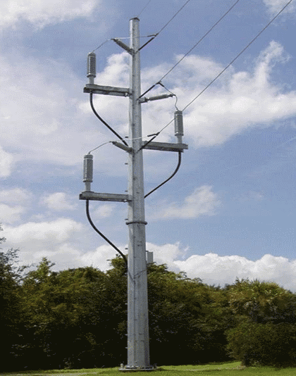
Terminations for transition of underground cables to overhead lines ( known as OH/OG ) are usually constructed for distribution networks with rated voltages up to 36 kV, for the connection of the distribution system at indoors or outdoors pre-assembled switchgears and also to avoid that overhead lines go through urban areas.
OH/OG are suitable for oil-paper and XLPE (Cross linked polyethylene) insulated cables (single core or 3-core) and are installed outdoors in a metallic structure anchored to the overhead line pole (wood, concrete or metal), as shown in Figure 1.
Metallic structures of OH/OG must be grounded.
Also Read: Overhead Lines Protection – Faults & Protection Devices
The height of the OH/OG metallic structure must be in accordance with the minimum insulation safety distance to ground defined by standards.
The cables shall be erected on the side of the pole away from oncoming traffic and they shall not be bent tighter than the manufacturer’s specified minimum internal bending radius, both during installation and after it has been set in position, what may require taller poles to ensure the minimum bending radius of the cable is not compromised. OH/OG shall be animal proofing.
Elbow Terminations
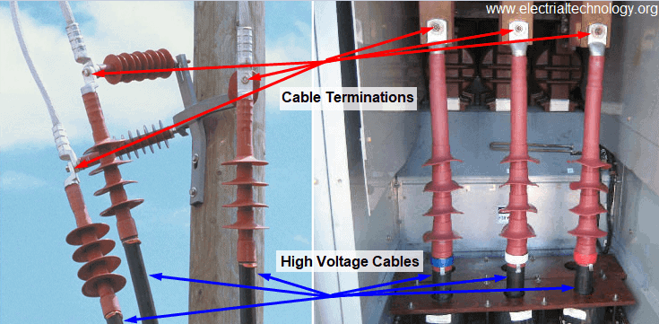
Connection of cables to equipment (transformers, motors or pre-assembled switchgears) terminals mostly uses cable terminations.
However particular conditions of the electrical installation or the equipment terminals may require that cable connection to the bushings shall be sealed.
For that purpose elbow terminations, like is shown in Figure 2 must be used.
A particular application of elbow terminations is cable connection to bushings of Ring Main Units (RMU).
RMU is a compact self-contained and totally insulated switchgear (SF6), normally used in secondary distribution networks.
The equipment is designed for internal arc withstand, has maintenance free live parts and can be easily extended at site.
Switching function and protection functions are achieved by switch-disconnetors associated to fuses or circuit breakers.
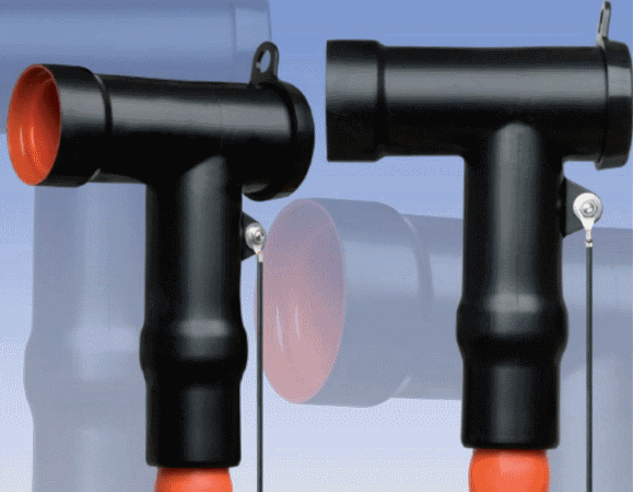
Elbow terminations are also used when more than one cable is required to be connected to the same bushing of equipment, and at Figure 3 it can be seen an example of an elbow termination for this situation.

Also Read: Choice Of Wiring System & Types Of Cables Used In Internal Wiring
Elastimold Cable Joints & Terminations
Elastimold is a very common trade mark of equipments and accessories for cable splicing and termination, for rated voltages up to 36 kV.
Elastimold cable terminations are available in single piece or modular designs, and models are suitable for transition from underground cable to bare overhead conductors, live-front equipment and elbow connections, both for indoor and outdoor applications.
They are suitable for use in oil, SF6 and air insulated high voltage switchgear, transformers, motors and capacitors.
Designs use advanced silicone rubber insulating materials to provide necessary creep, strike, weather sealing and contamination resistance, assuring proper performance in the most severe conditions.
Ferrite Bead: Tiny Cylinder in Power Cords & Cable. Why?
Units are compact and lightweight, allowing installation in restricted spaces and free-hanging applications.
Elastimold devices are also ATEX (derives from the French title of the 94/9/EC (European Comission) directive: “Appareils destinés à être utilisés enATmosphères Explosibles” ( Equipments to be installed in explosive atmospheres ) certified HV bushings for use within oil or air insulated switchgear and transformers installed in hazardous areas (potentially explosive atmospheres) including the oil, gas and petrochemical industries.
Equipment is manufactured according to IEC, ANSI/IEEE and CENELEC (IEC: International Electrical Commission. ANSI: American National Standards Institute. IEEE: Institute of Electrical and Electronic Engineers. CENELEC: European Commitee for Electrotechnical Standardization) standards.
Elastimold presents some special devices for particular applications:
Separable elbow connectors and their related accessories are load break connectors that provide a convenient method to connect/disconnect cable and equipment on power distribution systems.
Load break elbows include provisions for energized operation using standard hot stick tools, allowing load make/break operation and a visible disconnect.
Also Read: Submarine Cables – Construction, Characteristics, Cables Laying & Joints
Components can be isolated with insulated caps, plugs and parking bushings.
Metal Oxide Varistor (MOV) surge arresters are fully shielded, fully-submersible are constructed for overvoltage protection and 200 A separable connector interfaces for attachment to other Elastimold accessories.
Elastimold arresters provide high voltage lightning and switching surge protection of transformers, cable, equipment and other components typically located on underground power distribution systems.
Proper placement, voltage selection and coordination with riser pole arresters minimize damaging surge voltages by improving protective margins.
Typical applications include installing an arrester at the end of a radial system or at both ends of an open point on a loop system.
Additional arresters can be added at strategic locations upstream from the end point for optimum protection.
Fused elbows combine replaceable current-limiting fuses for OH/OG cable termination current protection and 200 A separable connector interfaces for attachment to other Elastimold accessories.
Another trade mark commonly used for cable splicing and termination equipment is Raychem.
Also Read: Why Power Transmission Cables & Lines are Loose on Electric Poles & Transmission Towers?
Terminations to GIS
When the space available for the installation of the substation is short or when the environmental conditions are extremely severe the usual solution is to install a GIS (Gas Insulated Substation).
This kind of equipment is a compact multi-component assembly, enclosed in a ground metallic housing where bus bars, circuit breakers, isolators and instrument transformers are installed , having as primary insulation medium a compressed gas – sulfur hexafluoride (SF6) – that assure the phase to ground insulation.
GIS are usually installed indoors, but models for outdoors installation also exist.
GIS are provided with cable termination enclosures where cable terminations will be installed.
Both enclosures and cable terminations are required in IEC Standard 60859 to meet specified dimension requirements in order to be interchangeable.
Cable terminations for GIS are suitable for gas, oil-paper and XLPE cable insulated and basically they have the same components that cable joints previously discussed.
Also Read: Cables Feeder Protection & Faults Types, Causes & Differential Protection
Features of GIS Cable termination
Main features of GIS cable terminations are:
- Cable lug
- Box body (aluminium alloy or similar).
- Reliable support insulator – High grade, non-tracking, epoxy insulators provide excellent mechanical and electrical characteristics. The insulators are compatible with SF6 gas by-products, ensuring long life of the termination. Design of the insulators also allows for an optional cable shield break.
- Filling compound (transformer oil, polybutene oil or similar).
- Stress control cone with bundle tape.
- Rigid cable support – The connector is locked in position by a threaded hood at the top of the support insulator. Electrical connection between the GIS and termination should not be subjected to the mechanical forces from the cable.
- Positive sealing system – A double “O” ring sealing system is used to seal between the termination oil compartment and the GIS SF6 compartment. Fully retained gaskets are compressed to seal the interior of the termination from the atmosphere.
- Earthing clamp.
Figure 4 shows a scheme of GIS cable termination; some models on the market do not require oil use and so no oil housing is required.
- Also Read: Types of Control & Communication Cables
Sealing system must be designed to prevent oil or gas from leaking into GIS.
A mating connection piece, which has to be fitted to the cable end, shall be made available by the GIS supplier.
Facilities to safely isolate a feeder cable and to connect a high-voltage test cable to GIS or the cable shall be provided.
Proper tools and accessories are required for termination for GIS installation:
- Panduit pliers – for installation of bundle tape around stress cone.
- Circlip pliers – for installation of top fitting.
- Adapter flange.
- Top fitting removal kit.
- Re-assembly kit
- Earthing kit.
- Screen connection.
Also Read: Electric Stress Control in Cable, Joints & Terminations
![]()