Rainwater Harvesting System Integrated With Sensors for Attic Temperature Reduction
 Ming Chian Yew
 Song Wei Wong1
 - 1Department of Mechanical and Material Engineering, Lee Kong Chian Faculty of Engineering and Science, Universiti Tunku Abdul Rahman, Cheras, Malaysia
- 2Department of Civil Engineering, Lee Kong Chian Faculty of Engineering and Science, Universiti Tunku Abdul Rahman, Cheras, Malaysia
This cool roof system focuses on utilization of rainwater harvesting systems by integrating the smart sensor to cool the roof and attic temperatures for the improvement of comfort level of building occupants. An ideal cool roof technology system is basically made up of these three components: (1) moving-air-cavity (MAC) ventilation, (2) solar-powered fan and (3) rainwater harvesting system. These three main components integrate to perform and control the cool roof system. Four small-scale cool roof models were designed and constructed to inspect the performance of the rooftop and attic temperatures. The experimental work was carried out indoors by employing the halogen lamp as the replacement for solar irradiation, while the ambient temperature is monitored to be around 29.8 °C throughout the test. The temperatures of the rooftop surface, MAC aluminum tube, and attic region were measured by K-type thermocouples to evaluate the performance of the cool roof designs. The solar-powered fans were incorporated into the MAC, which accelerated the airflow rate within the cavity and rejected the hot air out before transferring it to the attic region. Meanwhile, an innovative rainwater harvesting system was executed to cool the rooftop temperature rapidly by reducing the rate of heat transfer to the attic region. The result of this inventive cool roof system (Design Z) has successfully reduced the attic temperature by 10.8 °C compared to the normal metal deck roof model (Design W). The findings of the project revealed that the integrated cool roofing technology system comprises the ability to enhance the comfortability of building occupants toward a long-term sustainable development for a better world.
Introduction
A cool roof system is considered as a roofing system that has the capability to reduce the rate of heat transfer through the roof and attic, resulting in the reduction of the room temperature to provide the comfort level of occupants inside the buildings (Gupta and Tiwari, 2016). By introducing this cool roofing technology system with the combination of Moving-Air-Cavity (MAC) ventilation, solar-powered fan and rainwater harvesting system in the tropical country, it will enhance the comfortability inside the buildings, which acted as a low-cost method to save energy. Besides that, the MAC ventilation plays a vital role in preventing the heat transfer directly to the attic region. Therefore, the heat gained by the ceiling of the building was tremendously decreased, which also greatly reduced the need for mechanical cooling systems such as air conditioners.
A comparison between the roof and the wall of the landed buildings, most of the heat was gained by the roof due to its exposure area and the rate from the sun is higher during the daytime. In general, most of the rooftop design in Malaysia was constructed by the uppermost rooftop and a gypsum ceiling board underneath it. The roofing materials commonly used in Malaysia for factories and warehouses are metal deck roofing (Akbari and Kolokotsa, 2016; Yew et al., 2018). This study is mainly focusing on the metal deck roofing system. Furthermore, most of the ventilations in factories is poor and fairly airtight, mostly due to the lack of air circulation. As a result, the heat transmitted through the roof will keep circulating in the attic region, which generates the heat to the ambient air inside the building. Therefore, many research have been conducted to investigate and evaluate the performance of the cool roof systems in cooling the buildings (Yew et al., 2013; Stavrakakis et al., 2016; Pisello, 2017; José Manuel and Pablo, 2019; Yew and Yew, 2021).
In Malaysia, the average electricity consumption rises rapidly annually which shows a figure around 2,533 GWh per year. By 2020, electricity consumption is expected to increase about 30% while the present value is about 124,677 GWh (Tan et al., 2013). The issue of high energy consumption occurred when heat from solar radiation is transmitted and absorbed by the roof surface. This heat will further transmit through the roof tile and trapped in the attic which results in a hot ceiling. The heat will radiate and transfer from the hot ceiling to the occupants inside the building which results in an increase of temperature inside the indoor space. Furthermore, the level of discomfort ability will increase due to the temperature increase generally in both the surface building and the ambient air inside the building. The demand for cooling and ventilation systems will greatly increase which implies that more air conditioning systems will be used resulting in the increase of utility bills. Based on technical data recorded, the typical temperatures for a house on the sunny day (with an outdoor temperature of 32°C) and with no attic ventilation, the temperature at the roof sheath may reach as high as 77°C while the temperature at the attic floor can potentially achieved to 60°C. With this sunny condition, it further produces an uncomfortable environment in rooms which directly beneath the attic region (Air Vent Inc, 2013).
From all these indications that had been mentioned, an alternative design technique is needed to overcome these issues and it is found that the cool roof system is an appropriate method. A systematic cool roof design is the primary step taken in the cool roof system to reduce the heat gain from the sun. While minimizing the heat transfer into the attic, the MAC ventilation integrated with solar-powered fans system is essential to transfer the hot air before entering the ceiling. The rainwater harvesting system integrated with sensors is an alternative option to control the heat transfer to the MAC and attic region by using the thermostat-controlled system. Therefore, an active and smart cooling technology system is required for sustainable development in buildings.
The contribution of this project would help to reduce the attic temperature in the roof configuration with nearly zero energy consumption. A solar-powered fan acted as a renewable energy was utilized as an energy source for the active cool roof system, which enrolled in the practices of sustainable buildings development. Hence, implementing both active and passive approaches in cool roofing systems would improve occupants’ comfort level by minimizing the effect of heat penetrating into the buildings.
Experimental Design
The basic model of the cool roof system is the attic section. The basic model was built by using Perspex of thickness 5 mm. The dimensions of the basic model were 340 mm (L) × 360 mm (W) × 290 mm (H) and 490 mm (H), respectively. Supplementary Figure S1 shows the dimensions of the basic model with a roof area of 412 mm (L) and 340 mm (W) inclined at an angle 30° (Ong, 2011).
Figure 1 shows the entire design of the rainwater harvesting system with the combination of cooling tower, water tank and submersible pump to monitor the rooftop temperature.
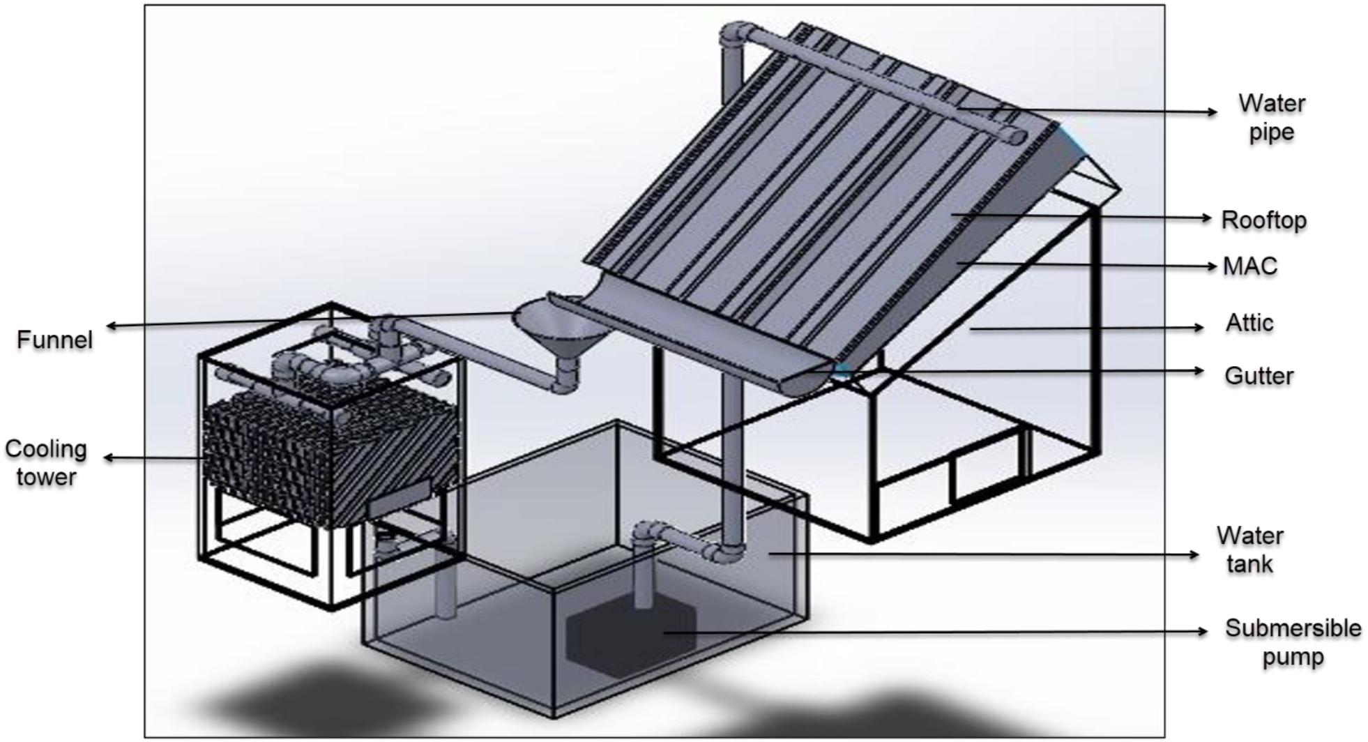
Figure 1. Experimental setup for the rainwater harvesting system.
Moving-Air-Cavity
The moving air cavity channel was construed by aluminum foil and steel rod as shown in Figure 2. Aluminum was used as the material for this design due to its high thermal transitivity characteristic. The inlet dimension of the MAC channel is designed to be smaller than the outlet dimension. In other words, a cubical cone shape was formed by gradually increasing the size of the cavity from the inlet dimension to the outlet dimension.
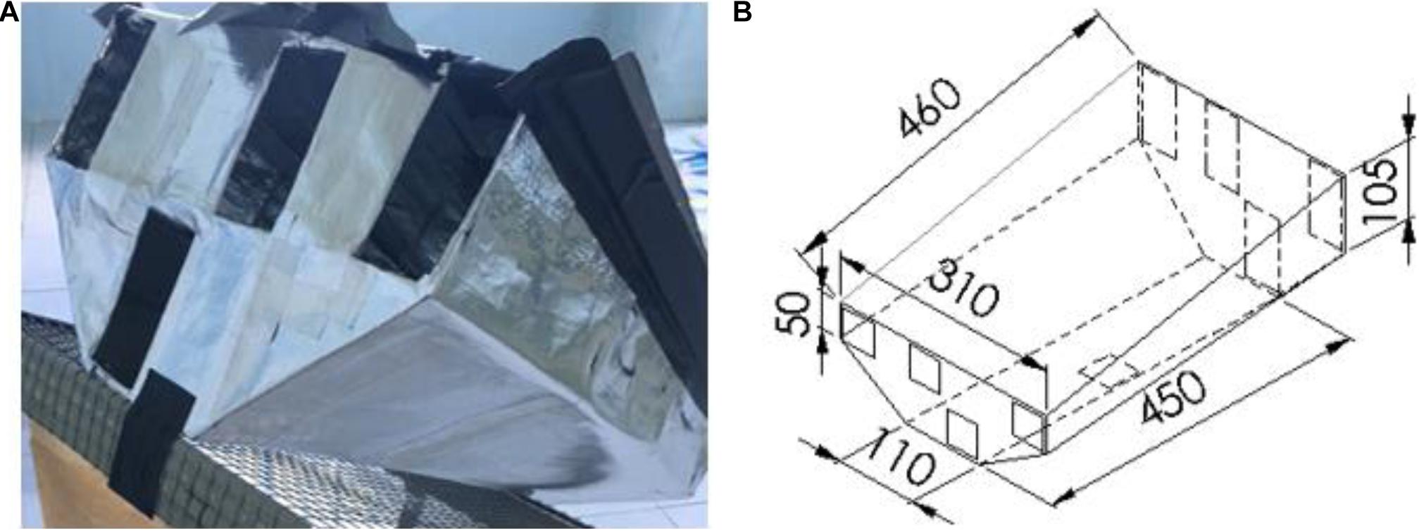
Figure 2. The diagram of MAC (A) experimental (B) AutoCAD drawing.
Furthermore, the bottom area of the cavity is also designed to be smaller than the area of the top cavity which with the dimension of 450 mm (length) × 110 mm (width) and 460 mm (length) × 310 mm (width), respectively (refer Figure 2B). The structure of the MAC was designed based on the buoyancy effect which enhances the removal rate of the hot air through the cavity outlet. The density of the hot air is lower than the cool air and it tends to flow upward according to the buoyancy effect. This design decreased the number of solar powered fans installed by providing a smooth path which directs the hot air to the high removal rate channel that directly interacts with the solar powered fan.
Solar-Powered Fans
Five solar-powered fans of dimensions: 4.5 cm 4.5 cm were connected horizontally and tied to a plastic mesh as presented in Figure 3A. This solar panel provides 12 V and 250 mA with a maximum power of 3 W. The airflow of each solar-powered fan was measured by using the hot wire thermo-anemometer airflow meter with telescoping probe, which is designed to fit into the center of the small openings. The MAC accommodated four channels to place four solar-powered fans that were tilted 30° from the vertical axis to align with the channel direction. The fifth solar-powered fan was attached underneath the center of MAC as shown in Figure 3B. The fans were then connected to the solar panel for obtaining the power source from the halogen spotlights.
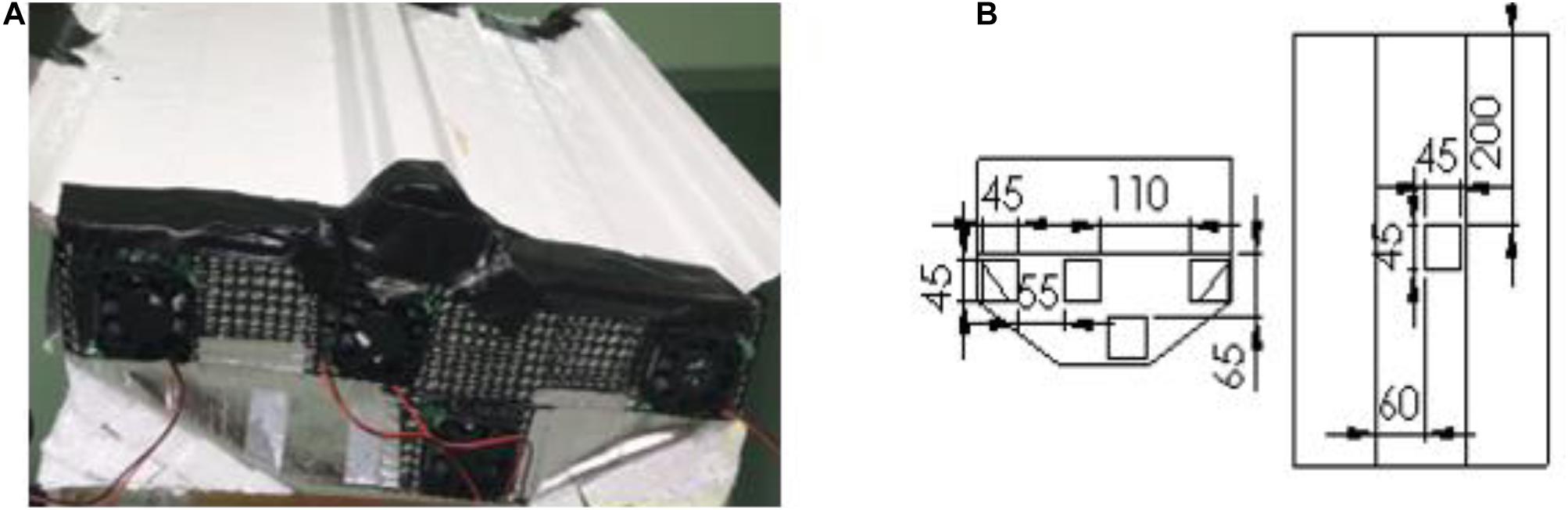
Figure 3. The solar-powered fans attached with MAC (A) experimental (B) AutoCAD drawing.
The air channel with uniform parallel design maximized the amount of air in the MAC. Air can act as a thermal insulation element to stop the heat conducted through the roof from transferring downward to the attic. The departmentalized design of MAC followed the dimension of solar-powered fans. It is to ensure that all the cool air induced by the solar-powered fans enter the MAC completely. Each solar-powered fan had an air channel to prevent the flow interruption from the other solar-powered fans, which slowed down the rate of airflow and the heat transfer.
Water Pump Integrated With Thermostat
A submersible water pump (DC-12V/4W, 3.33 liter/min flow rate) was used as an actuator that transfers the cool water from the water storage tank to the rooftop. The maximum pressure head of this pump is 1.3 meter which is energized by an AC current as shown in Figure 4. As mentioned, the water pump will be triggered by the thermostat when the desired temperature is achieved in the setting of the temperature sensor. For this experimental work, the temperature sensing for this thermostat was set to trigger the water pump at 60°C for the rooftop temperature.
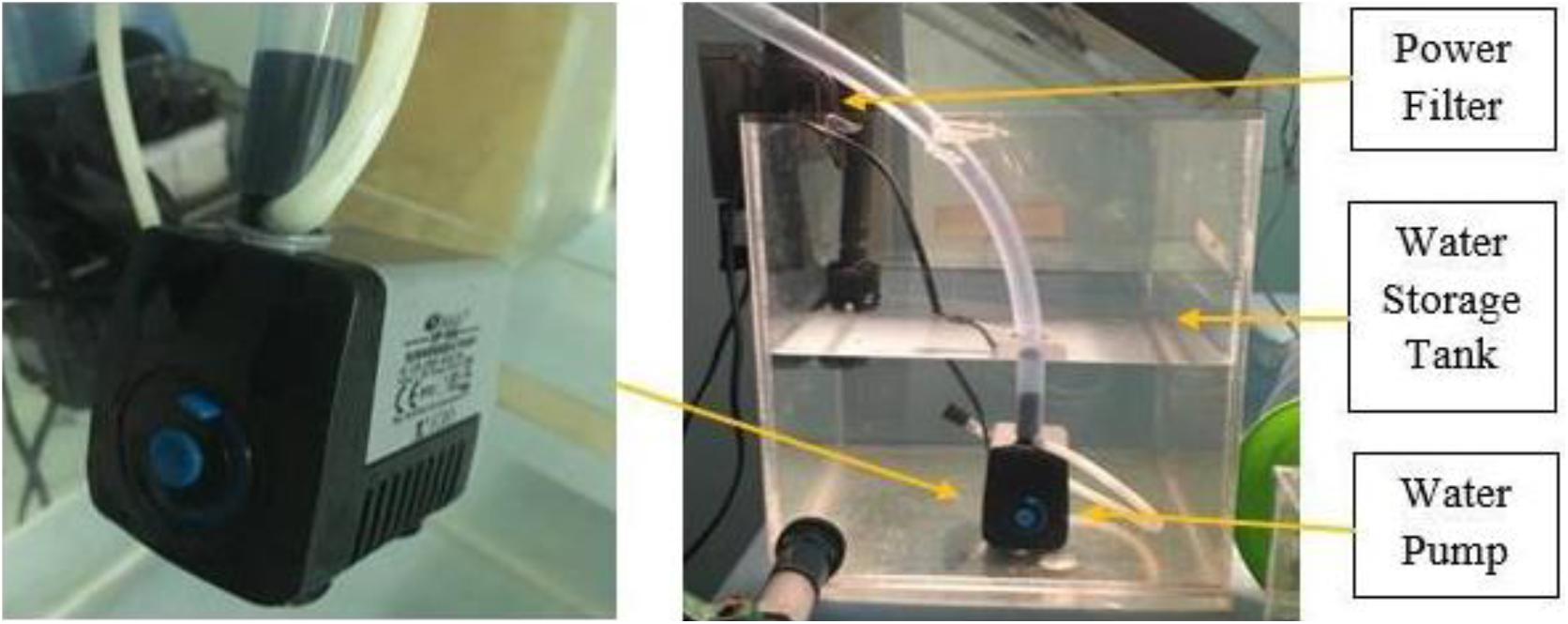
Figure 4. Water pump set up.
This water pump was specially designed and modified with the thermostat that performed as an automation control or smart sensor. Thermostat was used as a regulator that triggered the water pump based on the temperature value pre-set in the data. It has one connected temperature sensor and four connectors which are labeled as “1,” “2,” “C,” and “E” (earth). The live wires of the water pump and power filter were connected to the connector “C” which indicated the output of the thermostat. Meanwhile, the neutral wires of the three pin plug (power source) was connected with the water pump and power filter. The connector “E” which indicated as the earth of the circuit was connected to the earth wire from the power source as illustrated in Figure 5. In addition, the live wire from the three pin plug was connected to the connector “2” that completes the circuit design for this thermal sensing triggered pump (Yew et al., 2020).
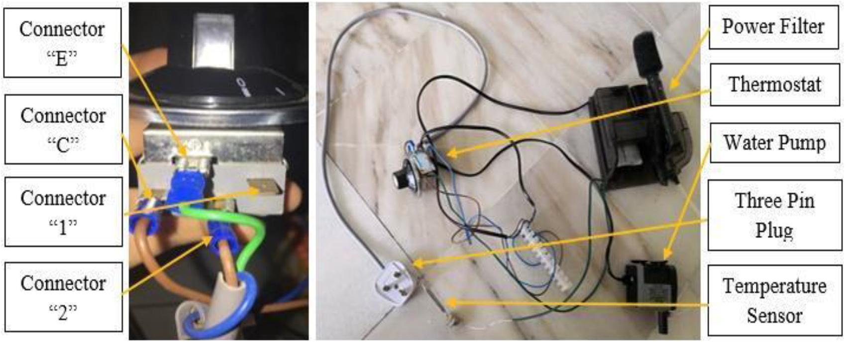
Figure 5. Circuit connection of thermal sensing triggered pump.
Cooling Tower
The cooling tower was designed to reduce the temperature of the heated water which flowed from the rooftop. The heat of the rooftop was absorbed by the cool water and released at the cooling tower to ensure the water temperature (about 28°C) in the storage tank is feasible for the cooling system. The design concept is based on the commercial cooling tower which is installed in current industrial.
The cooling tower in this model was constructed by the acyclic with dimensions of 210 mm (length) × 210 mm (width) × 410 mm (height). The heated water will flow through a bunch of cooling fill from the top of the cooling tower to the bottom pipe connection. The main objective of this cooling fill is to increase the total contact area of the heated water that enhances the effect of convection. A honeycomb shape was designed as the cooling fill that further increased the contact area. Each fill was cut and arranged in a stepped structure which directs the flow of the heated water as shown in Figure 6.
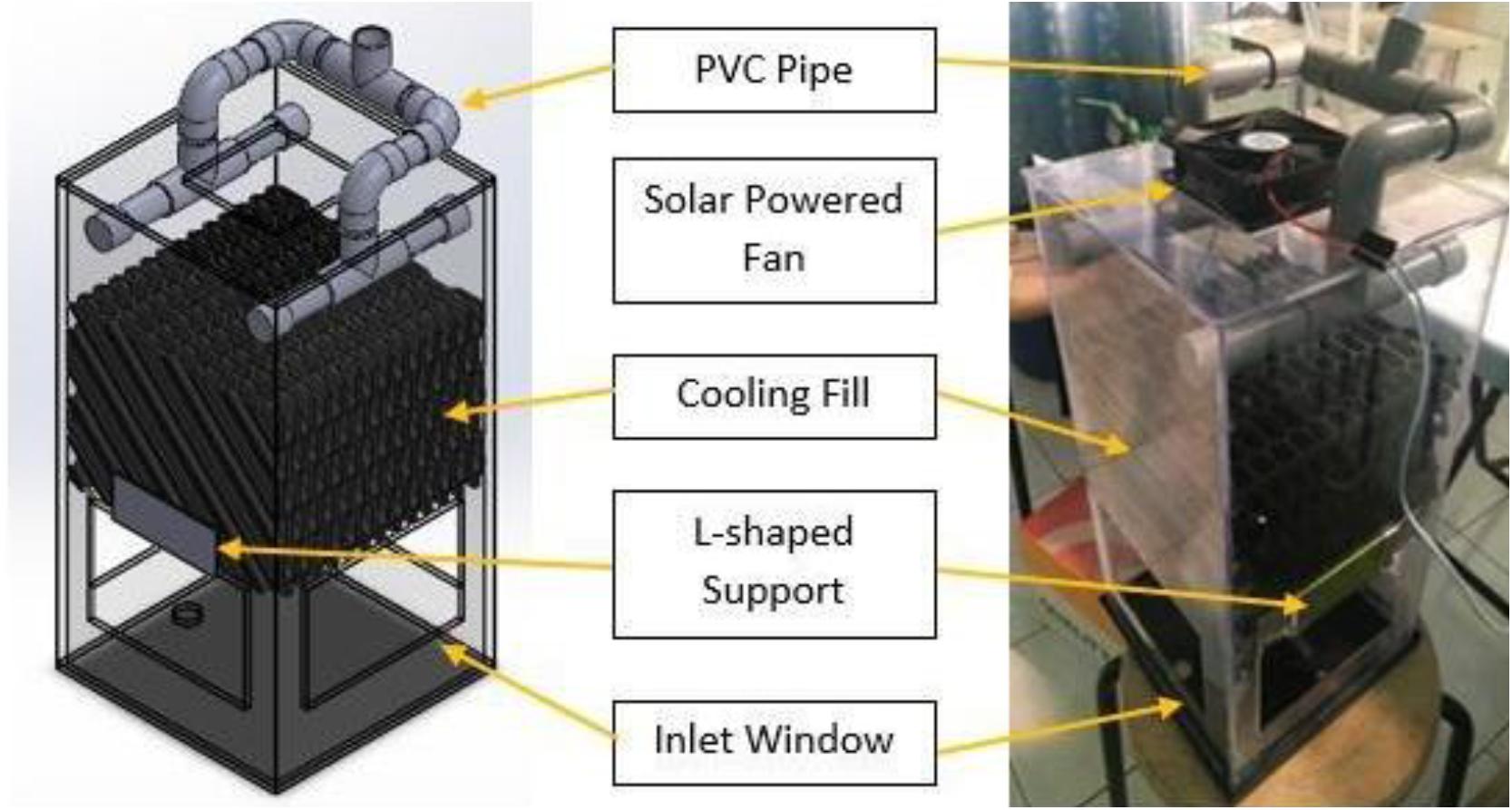
Figure 6. Cooling tower set up.
Furthermore, a solar powered fan was installed at the top of the cooling tower in order to induce the bulk movement of the air inside the tower. In this case, ambient cool air will enter the cooling tower through the inlet window (dimensions: 100 mm × 150 mm) opened at the side panel. The heated air will exit the cooling tower through the suction of the solar powered fan. Heat transfer was performed during the cooling fill that successfully released the heat energy from the water. In addition, a halogen lamp was used to provide irradiation to the solar panel that energized the solar fan to cool the heated water in the cooling tower.
Thermocouple Sensor Set Up
The data logger was set up to record the measured temperature form the thermocouple. Four K-type thermocouples with the measurement accuracy ± 0.75°C were used to measure the rooftop temperature, attic temperature, MAC aluminum tube, and ambient temperature. In this case, a data logger was used to provide four channel data monitoring throughout the experiment. The position of the thermocouple was fixed throughout the four model testing in order to compare the cooling efficiency of each roof configuration as shown in Figure 7. The thermocouple sensor 1 was directly attached to the roof top surface whereas the sensor 2 was positioned inside the MAC channel which is 30 mm below the sensor 1. The thermocouple sensor 3 was installed at the attic region. It was positioned 150 mm below the second sensor in the MAC channel. All data was recorded at 1 min interval throughout the 25 min cool roof testing.
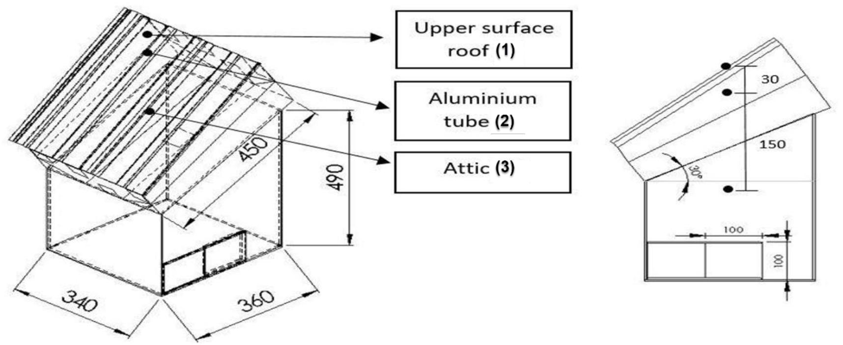
Figure 7. The thermocouple sensors location.
Halogen Lamps Set Up
Halogen Lamp was used as a heat emitter in this project in order to heat up the roof top model. Halogen lamps create light by heating the filament inside the bulb that generate a lot of heat during operation. As a result, 90% of the energy was wasted to generate heat that makes the efficiency much lower than the fluorescent lamp which only wasted 30% energy in heat. In other ways, halogen lamps were considered as a good heating agent that provide irradiation and heat radiation during operation.
In this project, two 500 W halogen lamps were set up according to an incident angle of 10° and 15°, respectively with the model rooftop. The maximum temperature of the metal deck rooftop can be reached is about 80 °C when exposed to daily solar radiation (4,000–5,000 Wh/m2) in Malaysia (Yew et al., 2018). The distance of the halogen lamps from the roof center was 45 cm and 47 cm, respectively. Additionally, the third 500 W halogen lamp was used to supply the solar power to the solar-powered fans.
Roof Models Set Up
This project had constructed four roof models, the normal metal deck roofing (Design W), MAC integrated with metal deck roofing (Design X), MAC integrated with metal deck roofing and solar powered fans (Design Y) and MAC integrated with metal deck roofing, solar-powered fans and rain harvesting system (Design Z) are shown in Figure 8. The four roof models were tested and compared their performances in terms of roof and attic temperatures.
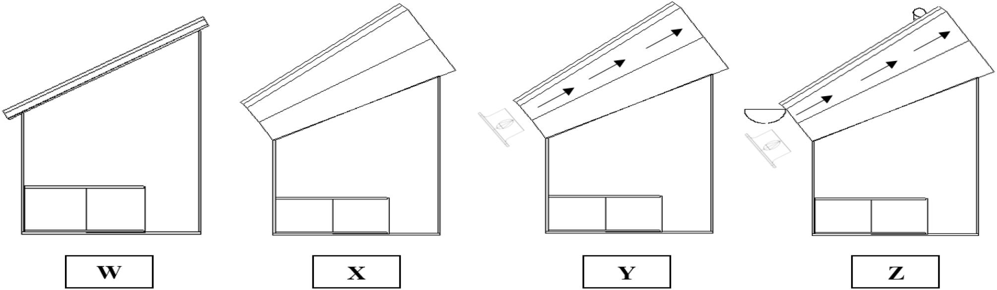
Figure 8. The roof model designs W, X, Y, and Z.
Results and Discussion
Metal Deck Roof (Design W)
The experiment was started with a controlled experiment roof model composed solely of a conventional metal deck roofing (Design W). Figure 9 shows the results obtained and presented in a graph of temperature versus time for a total experiment duration of 25 min. In this roof configuration, the rooftop temperature and attic temperature reached a maximum of 78.6 °C and 40.7°C, respectively. The experiment was carried out in a stable ambient temperature condition, which begins with 29.4°C and ends with 30.5°C throughout the 25 min of heating process. The rate of increase in ambient temperature was about 0.044°C/min due to the heat generated by the halogen lamp being transferred to the surrounding ambient air of the roof models.
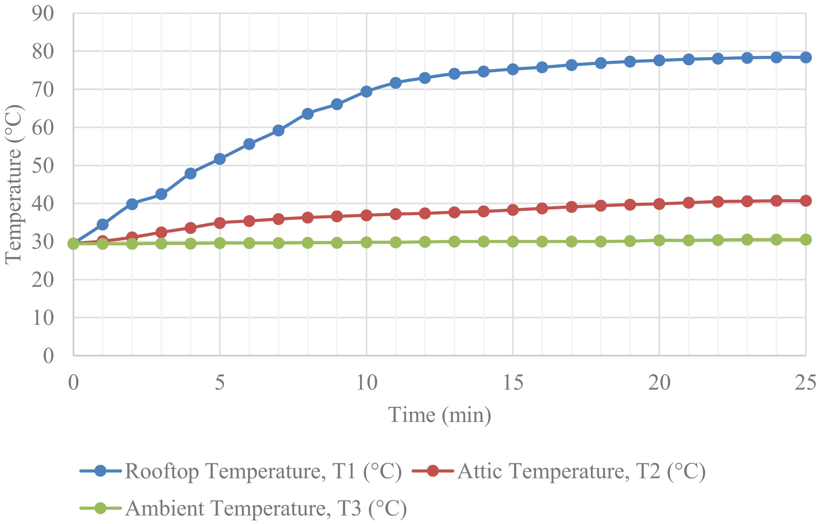
Figure 9. Performance of metal deck roof (Design W).
The gradient of the curve for rooftop temperature was about 3.99°C/min in the first 10 min, which was direct exposure to the halogen lamps. The curve became constant and stable after 15 min of heating process until the end of the test. Meanwhile, 40.7°C is the maximum attic temperature. The heating rate of attic temperature was about 0.586°C/min in the first 15 min and became constant after 20 min of testing.
MAC Ventilation (Design X)
The rooftop temperature increased dramatically from 29.6 to 78.6°C throughout the 25 min of the test, it is slightly higher than the roof Design X due to the heat reflected back to the underneath of the roof by the aluminum tubes. The gradient of the curve for rooftop temperature was about 4.25 °C/min in the first 8 min (as shown in Figure 10).
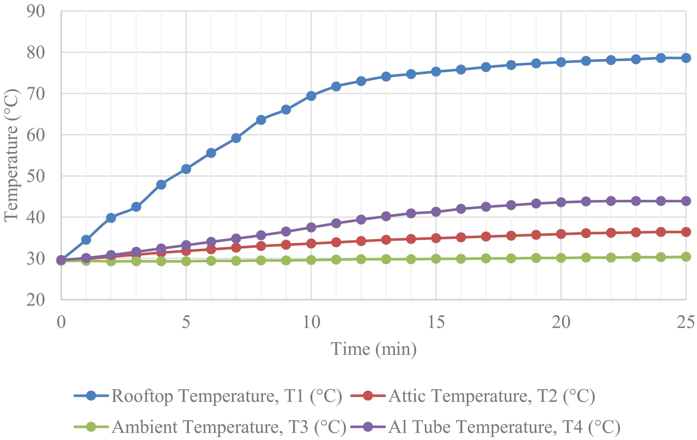
Figure 10. Performance of metal deck roof with MAC (Design X).
The rate of temperature increase in aluminum tube and attic in the first 5 min was 0.56°C/min and 0.40 °C/min, respectively. Based on the results, the rate of temperature increase in the aluminum tube was higher than the rate in the attic region due to the MAC being directly attached below the rooftop that received much higher heat transmitted. Both the temperature of aluminum tube and attic reached a constant temperature after 20 min of testing. The maximum attic temperature of roof Design X was 36.4 °C. In this roof configuration, the maximum temperature difference between the rooftop surface and attic region was 42 °C. This temperature variance was much higher than the maximum temperature difference between the aluminum tube and attic region, which measured to be 7.5 °C only. In this case, the maximum temperature variance between the aluminum tube and rooftop surface was 34.7°C. The attic temperature increased about 7°C throughout the 25 min of heating process. The implementation of MAC ventilation created the buoyancy effect to transfer the hot air out by natural means. The MAC ventilation was inclined with an angle 30° that was designed based on the characteristic of fluid thermal expansion, which enhanced the convective velocity of the air inside the cavity. The convective velocity of the heated surface will increase as the angle of inclination increases (Abhijit et al., 2019). The thermal effect creates a natural circulation of air, because as warm air rises, cooler air enters. It can be indicated that the implementation of MAC played an important role for attic temperature reduction.
MAC With Solar-Powered Fan (Design Y)
The result of roof model Design Y was plotted in graph as shown in Figure 11. For this cool roof system, the rooftop and aluminum tube reached a maximum temperature of 77.8°C and 36.3°C, respectively. The graph obtained showing that the peak temperature for the enclosed attic region was 30.9°C. The rate of increase in ambient temperature was 0.036°C/min due to the heat generated by the halogen lamp transferred to the ambient air surrounding the testing model. In this case, a condition of constant ambient temperature was provided during the testing operation that started and finished with a temperature of 29.4 and 30.3°C, respectively.
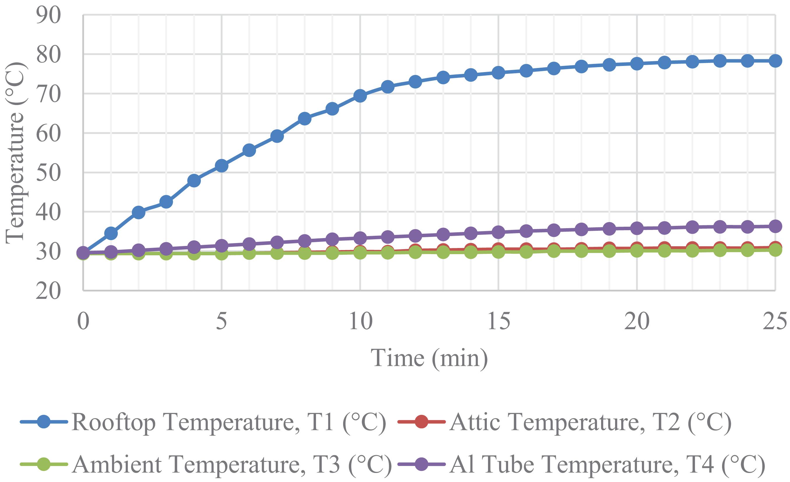
Figure 11. Performance of MAC-solar powered fan (Design Y).
Meanwhile, the rate of temperature increase in aluminum tube and attic in the first 3 min was 0.21 and 0°C/min, respectively. As a result, the attic temperature remained constant at 29.4°C in the first 5 min of the heating process due to the heat transmitted from rooftop was executed by the MAC-solar powered fan before transferring it to the attic region. The temperature of aluminum tube and attic both became constant after 20 min of testing.
For this cool roof system (Design Y), the maximum temperature difference between the rooftop surface and the attic region was 46.9°C. This temperature variance was larger than the maximum temperature difference which measured to be 41.5°C between the rooftop surface and MAC aluminum tube with solar-power fan. In addition, the maximum temperature variance between the aluminum tube with solar-powered fan and attic region was 5.4°C. The attic temperature increased only about 1.5°C throughout the entire testing (25 min heating process) from 29.4 to 30.9°C. By itself, the thermal effect cannot create the high volume of air movement needed for effective ventilation. That is why the influence of wind speed by installing the solar-powered fan is the key element in the design of an effective powered ventilation system (Zhao et al., 2019). This positive result is due to the 5 solar-powered fans having transferred the hot air from the aluminum tubes efficiently. The airflow of each solar-powered fan is about 0.68 m/s as measured by using the hot wire thermo-anemometer airflow meter with telescoping probe, which is designed to fit into the center of the small openings.
MAC and Solar-Powered Fan Integrated With Rainwater Harvesting System (Design Z)
The result obtained from the innovative cool roofing technology system with the integration of MAC-solar powered fan and rainwater harvesting system was plotted in graph as shown in Figure 12. The rooftop temperature fluctuates throughout the entire heating process due to the cooling effect provided by the rainwater harvesting system with the controlled approach. The ambient temperature increased at a rate of 0.056°C/min due to the ambient air surrounding the model being heated by the halogen lamp. As a result, a condition of constant ambient temperature was provided during the testing operation that started and finished with a temperature of 29.4 °C and 30.8°C, respectively. For this experimental work, the rooftop temperatures for Designs W, X and Y are about the same. A slight difference in the rooftop temperature for Designs X and Y as compared to Design W is due to the heat reflected back to the underneath of the roof. However, the rooftop temperature for Design Z is controlled by using the thermostat trigger point at 60°C for cooling the rooftop before transferring the hot air to the attic region.
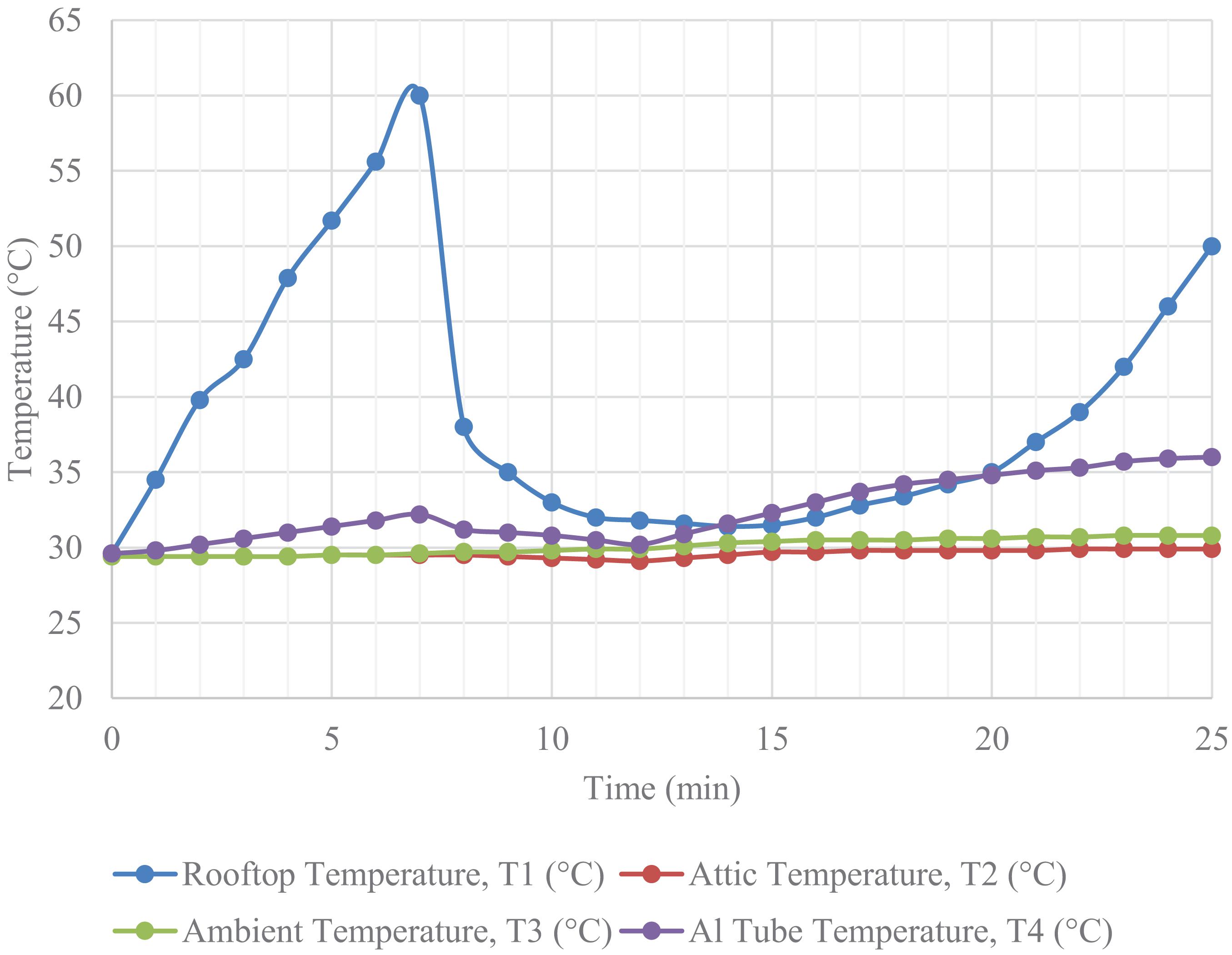
Figure 12. The water flow cycle of the rainwater harvesting system.
For this roof configuration, the maximum temperature of the rooftop and MAC aluminum tube was 60 and 36.0°C, respectively in the first 7 min before triggering the thermostat to cool the rooftop surface with cool water. In this experimental work, the thermostat was set to trigger the thermocouple sensor on the rooftop at 60°C by switching on the submersible water pump for watering and cooling the rooftop for the duration of 5 min. The process of the water flow cycle (cool > hot > cool) of the rainwater harvesting system as shown in Figure 13.
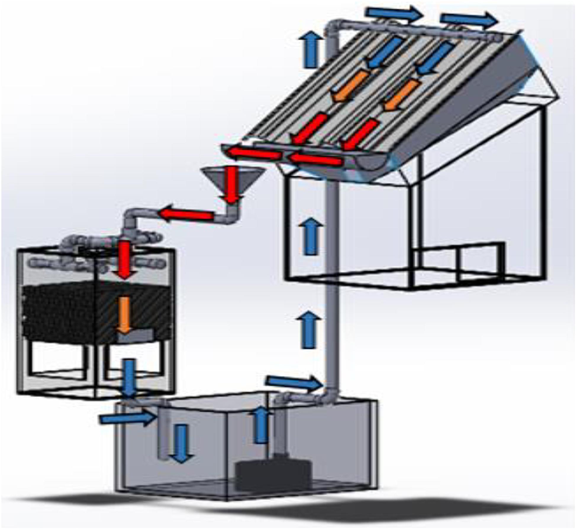
Figure 13. Performance of MAC-solar powered fan with rainwater harvesting system (Design Z).
The rooftop temperature dropped rapidly for the duration of 5 min (from 60 to 31.8°C) when the rooftop temperature reached at 60°C by triggering the thermostat for cooling as shown in the graph. It can be indicated that this temperature was considered as a turning point for this cool roof system with the integration of rainwater harvesting system, which showed an alternative and smart option for users to cool the rooftop temperature significantly. At the same time, the temperatures of MAC aluminum tube and attic region could reduce directly due to this smart cool roofing technology system.
Based on the graph obtained, the two peak temperatures of the rooftop surface were 60 and 50°C at 7 and 25 min, respectively. The maximum rooftop temperature was controlled by the thermostat sensor, which was set at the temperature of 60°C measured by the thermocouple sensor. This phenomena analyzed that the reduction of rooftop surface temperature is due to the implementation of rainwater harvesting systems. Furthermore, the rate of temperature increase in aluminum tube and attic in the first 3 min was 0.3°C/min and 0°C/min, respectively. As a result, the attic temperature remained constant at 29.4°C in the first 5 min of the heating process due to the heat transmitted from rooftop being executed by the MAC-solar powered fan before it transferred to the attic region.
For this roof Design Z, the MAC-solar powered fan incorporated with controlled rainwater harvesting system increased the comfort level of building occupants by reducing the temperatures of rooftop surface, aluminum tube ventilation and attic temperature drastically. In order to save the energy of the rainwater harvesting system, the water pump was set to water the rooftop surface for the duration of 5 min. The step will be repeated when the rooftop surface is heated up to 60°C after cooling. This can be explained and linked to our sweating body during a hot day. It is a surprisingly effective method of returning our body to its core temperature by natural means. As the droplets on our skin transition from liquid to gas, their evaporation pulls warmth away from our body, cooling the blood underneath our skin, which goes back to our body’s core, reducing our overall body temperature or building temperature with the water cooling (Han et al., 2017).
Comparison of Attic Temperature
The comparison of attic temperature for the four cool roof designs were plotted in a graph as shown in Figure 14. Based on the results obtained from roof Design W, the attic temperature increases rapidly from 29.5 to 34.9°C in the first 5 min and gradually increases at a rate of 0.24 °C/min throughout the 25 min of heating process. However, the roof Design X also increased from 29.4 to 36.4°C throughout the 25 min of testing with a heating rate of 0.28 °C/min. In contrast, the attic temperatures of the other two cool roof design models remained constant in the first 5 min and slightly increased until it reached an equilibrium after 25 min of heating process. As a result, the cool roof system implemented in design W has the highest attic temperature which reached a maximum of 40.7°C as compared to the other three cool roof designs.
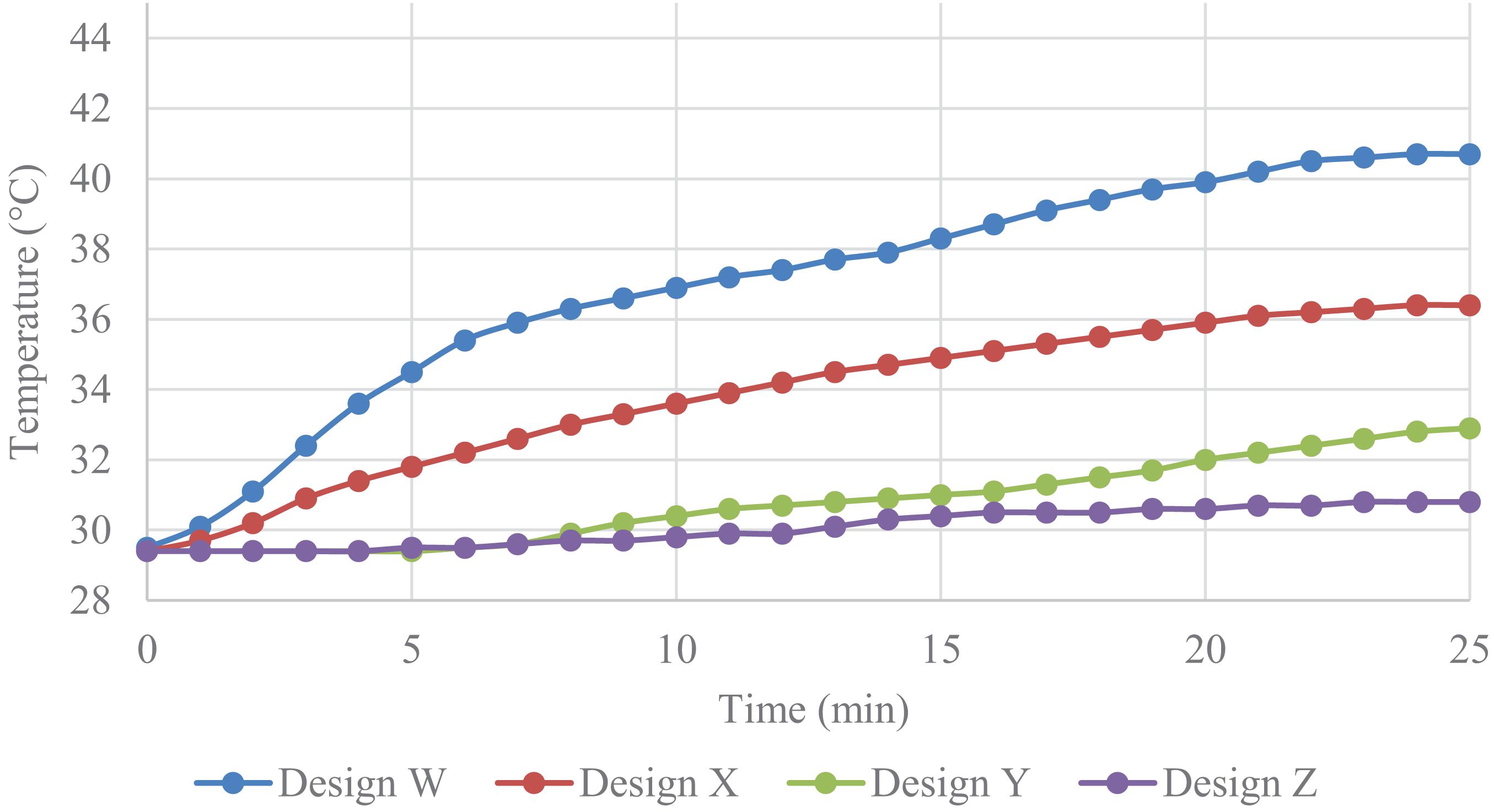
Figure 14. Performances of attic temperature of roof Designs W, X, Y and Z.
The maximum attic temperature different between the cool roof Design W and Design X was 4.3°C. This result indicates the effect of applying MAC between the rooftop and attic region in the reduction of attic temperature. The MAC was inclined with an angle that was designed based on the characteristic of fluid thermal expansion which enhanced the convective velocity of the air inside the cavity. According to the researcher Pradhan, the convective velocity of the heated surface will increase as the angle of inclination increases (Abhijit et al., 2019; Chen and Lu, 2020). In this case, the heat energy trapped in the attic region will be transferred to the MAC which reduces the temperature inside the attic region.
The cool roof system in Design Y additionally decreased the attic temperature of Design X by up to 7.8°C with the integration of MAC with solar-powered fans. In other words, the solar powered fans had reduced about 3.5°C of attic temperature as compared with the normal MAC system in Design X. As a result, the solar powered fans had increased the convective velocity of the fluid which accelerates the hot air removal rate inside the MAC. Figure 14 shows the performance of attic temperature reduction in Design Y (MAC-solar powered fan).
Design Z has achieved the lowest attic temperature at about 29.9°C among the other cool roof design models. The maximum attic temperature different between the Design Z and Design X was 10.8°C. This result indicates that the integration of MAC-solar powered fans and rainwater harvesting systems have significantly reduced the attic temperature. The rainwater harvesting system that was implemented in this design directly and indirectly cooled the attic temperature by decreasing the rooftop temperature. The heated water was transferred to the water tank by this system to reduce the heat energy transfer into the enclosed attic region.
Summary of the Performances of the Different Roof Model Designs
The conventional metal deck roof was compared with a new cool roof system. The cool roofing system with the integration of MAC, solar-powered fans and rainwater harvesting system had led to the best performance in the reduction of roof and attic temperatures. The MAC aluminum tube implemented a highly reflectivity surface which promoted the radiative cooling and buoyancy effect. The solar-powered fans had improved the mass flow of air for better heat transfer between ambient air and heat trapped in the MAC. An innovative rainwater harvesting system shows a substantial improvement in reducing the rooftop temperature rapidly. The performance of each roof design is summarized in Table 1. The roof Design Z had the lowest attic temperature and maintained the coolest attic among all roof models. This invention indicates that the combination of MAC-solar powered fan and rainwater harvesting system played an important role in the reduction of attic temperature.
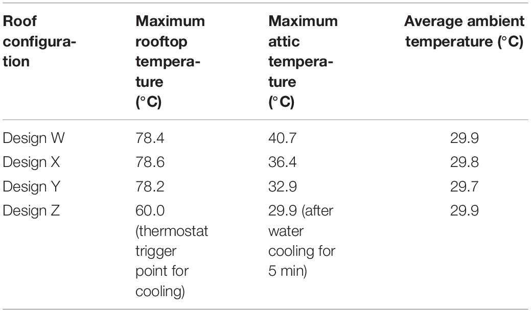
Table 1. The cooling effect of four cool roof designs.
Conclusion
In this research project, an active cool roof system that integrated with different roof configuration was investigated to enhance the attic temperature reduction. Four cool roof prototypes were fabricated and tested indoors with a solar simulation by halogen lamp. The combination of MAC solar powered fan and rainwater harvesting system (Design Z) performed the best cooling effect among the other cool roof designs. A temperature reduction of up to 10.8°C in the attic region was achieved as compared with the metal deck roof system (Design W).
Incorporation of solar powered fan (Design Y) into the cool roof system that additionally reduces about 3.5°C of attic temperature as compared to the normal MAC system in roof Design X. A force convection was introduced by the solar powered fan that increased the convective velocity of the air inside the cavity. As a result, the removal rate of the hot air will be accelerated by this configuration to reduce the heat transfer into the attic region.
The rainwater harvesting system showed a significant reduction in rooftop temperature from 60°C to 31.4°C as the cooling duration was set to be 5 min by the system. The heat radiated by the halogen lamp was directly absorbed and insulated by the cooling agent in this system that resulted in a temperature reduction rapidly. The rate of temperature increase in the attic region was reduced by the reduction of heat energy transferred from the rooftop to the attic region.
In conclusion, this eco-friendly cool roof system is able to reduce the attic temperature that enhances the comfortability inside the building occupants toward clean and sustainable energy utilization.
Data Availability Statement
The original contributions presented in the study are included in the article/supplementary material, further inquiries can be directed to the corresponding author/s.
Author Contributions
MCY supervised the project. SW wrote the original manuscript and conducted the experimental work. MCY, MKY, and LS analyzed, edited, and proofread the manuscript. All authors contributed to the manuscript revision and approved the submitted version of the manuscript.
Funding
We gratefully acknowledge the laboratory facilities support from Lee Kong Chian, Faculty of Engineering and Science, Universiti Tunku Abdul Rahman.
Conflict of Interest
The authors declare that the research was conducted in the absence of any commercial or financial relationships that could be construed as a potential conflict of interest.
Supplementary Material
The Supplementary Material for this article can be found online at: https://www.frontiersin.org/articles/10.3389/fbuil.2021.647594/full#supplementary-material
Supplementary Figure 1 | The dimensions of basic cool roof model (all units in mm).
References
Abhijit, G., Akshat, J., and Kaustav, P. (2019). Computation and physical explanation of the thermo-fluid-dynamics of natural convection around heated inclined plates with inclination varying from horizontal to vertical. Int. J. Heat Mass Transfer 135, 1130–1151. doi: 10.1016/j.ijheatmasstransfer.2019.01.054
Air Vent Inc (2013). Principles of Attic Ventilation A comprehensive course for Understanding and Planning attic Ventilation Systems. Buffalo, NY: AIR VENT INC.
Akbari, H., and Kolokotsa, D. (2016). Three decades of urban heat islands and mitigation technologies research. Energy Build. 133, 834–842. doi: 10.1016/j.enbuild.2016.09.067
Chen, J., and Lu, L. (2020). Comprehensive evaluation of thermal and energy performance of radiative roof cooling in buildings. J. Build. Eng. 33:101631. doi: 10.1016/j.jobe.2020.101631
Gupta, N., and Tiwari, G. (2016). Review of passive heating/cooling systems of buildings. Energy Sci. Eng. 4, 305–333.
Han, R., Xu, Z., and Qing, Y. (2017). Study of passive evaporative cooling technique on water-retaining roof brick. Proc. Eng. 180, 986–992. doi: 10.1016/j.proeng.2017.04.258
José Manuel, A., and Pablo, L. R. (2019). Roof ponds combined with a water-to-air heat exchanger as a passive cooling system: experimental comparison of two system variants. Renew. Energy 141, 195–208. doi: 10.1016/j.renene.2019.03.148
Ong, K. S. (2011). Temperature reduction in attic and ceiling via insulation of several passive roof designs. Energy Conv. Manag. 52, 2405–2411. doi: 10.1016/j.enconman.2010.12.044
Pisello, A. L. (2017). State of the art on the development of cool coatings for buildings and cities. Solar Energy 144, 660–680. doi: 10.1016/j.solener.2017.01.068
Stavrakakis, G. M., Androutsopoulos, A. V., and Vyörykkä, J. (2016). Experimental and numerical assessment of cool-roof impact on thermal and energy performance of a school building in Greece. Energy Build. 130, 64–84. doi: 10.1016/j.enbuild.2016.08.047
Tan, C. S., Maragatham, K., and Leong, Y. P. (2013). Electricity energy Outlook in Malaysia. IOP Conf. Ser. Earth Environ. Sci. 16:012126.
Yew, M. C., Ramli Sulong, N. H., Chong, W. T., Poh, S. C., Ang, B. C., and Tan, K. H. (2013). Integration of thermal insulation coating and moving-air-cavity in a cool roof system for attic temperature reduction. Energy Conv. Manag. 75, 241–248. doi: 10.1016/j.enconman.2013.06.024
Yew, M. C., and Yew, M. K. (2021). “Chapter: 12 – active and passive systems for cool roofs,” in Woodhead Publishing Series in Civil and Structural Engineering. Eco-efficient Materials for Reducing Cooling Needs in Buildings and Construction, eds F. Pacheco-Torgal, L. Czarnecki, A. L. Pisello, L. F. Cabeza, and C. Granqvist (Sawston: Woodhead Publishing), 275–288. doi: 10.1016/B978-0-12-820791-8.00012-2
Yew, M. C., Yew, M. K., Saw, L. H., and Beh, J. H. (2020). Active cool roof system for attic temperature reduction. IOP Conf. Ser. Earth Environ. Sci. 476:012131. doi: 10.1088/1755-1315/476/1/012131
Yew, M. C., Yew, M. K., Saw, L. H., Ng, T. C., Chen, K. P., Rajkumar, D., et al. (2018). Experimental analysis on the active and passive cool roof systems for industrial buildings in Malaysia. J. Build. Eng. 19, 134–141. doi: 10.1016/j.jobe.2018.05.001
Keywords: cool roof, rainwater harvesting, active system, sensor, sustainable buildings
Citation: Yew MC, Wong SW, Yew MK and Saw LH (2021) Rainwater Harvesting System Integrated With Sensors for Attic Temperature Reduction. Front. Built Environ. 7:647594. doi: 10.3389/fbuil.2021.647594
Received: 30 December 2020; Accepted: 22 March 2021;
Published: 23 April 2021.
Edited by:
Yaolin Lin, University of Shanghai for Science and Technology, ChinaReviewed by:
Faming Wang, Central South University, ChinaHaoshan Ren, City University of Hong Kong, China
Copyright © 2021 Yew, Wong, Yew and Saw. This is an open-access article distributed under the terms of the Creative Commons Attribution License (CC BY). The use, distribution or reproduction in other forums is permitted, provided the original author(s) and the copyright owner(s) are credited and that the original publication in this journal is cited, in accordance with accepted academic practice. No use, distribution or reproduction is permitted which does not comply with these terms.
*Correspondence: Ming Chian Yew, yewmc@utar.edu.my; yewmingchian@gmail.com