Determination Method of Excavation Damage Zone Based on Surrounding Rock Damage-Fracture Ratio in Underground Engineering
 Haosen Guo
 Jiaqi Tong
 Qiancheng Sun
 Xu Yang
 Wenjun Luo1,2
 - 1Jiangxi Key Laboratory of Disaster Prevention-mitigation and Emergency Management, Nanchang, China
- 2School of Civil Engineering and Architecture, East China Jiaotong University, Nanchang, China
- 3National Field Observation and Research Station of Landslides in Three Gorges Reservoir Area of Yangtze River, Yichang, China
- 4College of Civil Engineering and Architecture, China Three Gorges University, Yichang, China
The depth of the excavation damage zone in the surrounding rock mass is an important parameter to determine the support design scheme, and is also of great reference significance to evaluate the stability of the surrounding rock. An acoustic test is the most commonly used method to obtain the depth of the excavation damage zone in surrounding rock. However, under high stress conditions, the surrounding rock is seriously broken and the internal structural planes are significantly developed, leading to the test error reaching meter-level. This paper, based on dimensional analysis, proposed the surrounding rock damage-fracture ratio R, which was defined as the depth of excavation damage zone to the depth of highly damaged zone, to characterize the relationship between the excavation damage zone and highly damaged zone. The established indicator considered the stress condition of the engineering zone, rock integrity, tunnel excavation span, and rock fracture zone depth and was verified with allowable error in engineering practice. The results show that the model can overcome the limitations of the acoustic wave testing method in surrounding rock testing of deep underground caverns, and the method of determining the depth of the surrounding rock damage zone based on the damage-fracture ratio R provides a practical and alternative method for determining the damage zone of surrounding rock excavation.
Introduction
In the early 1980s, a large number of verification and promotion work on the supporting theory of loose circle, based on the excavation damage zone (EDZ) in domestic mines, was carried out. Kelsall et al. (1984) put forward the importance of the excavation damage zone of the surrounding rock. The academic seminars, 1988 in Winnipeg, Canada, 1998 in Paris, and 2003 in Luxembourg, are based on the excavation damage zone (EDZ) and safe storage of the waste issues related to the theme, and greatly promoted the scholars in the research of the excavation damage zone (EDZ). Harrison, et al. (2000) hold the opinion that the damage in the surrounding rock can be divided into inevitable damage during excavation and extra damage caused by the excavation method. Zou and Xiao, (2010); Zhou and Qian, (2007), according to some engineering examples, put forward the theory of zonal disintegration in the excavation damage zone. Eberhardt and Diederichs, (2012) further distinguished the excavation damage from construction damage zone (CDZ)and stress-induced excavation damage zone, (EDZSI). Siren, et al. (2015) proposed the concept of excavation disturbed zone (EdZ), which is in essence the same as the excavation disturbed zone (EDZ) proposed by Malmgren, (2007). Yang et al. (2020) estimated the rock mass properties of the excavated damage area (EDZ) based on the generalized Hoek-Brown damage criteria. Fan et al. (2021) and Feng et al. (2022) also analyzed the influences of stress unloading path induced by blasting excavation and tunnel boring machine (TBM) excavation on the EDZ using theoretical calculation and numerical simulation. The study of rock burst is also involved in the energy change of the excavation damage zone (Fan et al., 2015; Feng et al., 2015; Yu et al., 2022).
In fact, whatever the causes of damage, construction personnel are more focused on the depth of rock damage in the surrounding rock, which is vital to determine the economic and reasonable supporting scheme. Therefore, the surrounding rock can be divided into two major categories: excavation damage zone and the original rock zone (Figure 1).
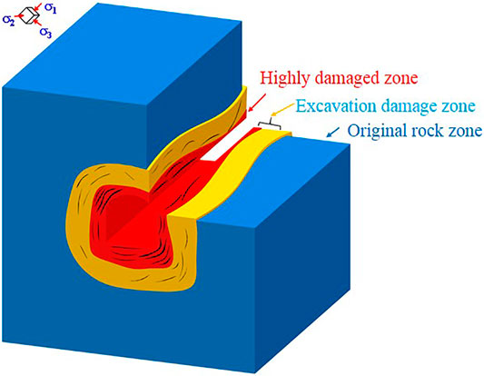
FIGURE 1. Two major categories in surrounding rock.
The original rock zone refers to the area not affected by excavation. The excavation damage zone (EDZ) is characterized by internal fissure expansion and the acoustic wave velocity falling; it is partially connected to isolated damage and is invisible, in which the observed interconnected macro-fractures are defined as the highly damaged zone (HDZ). Scholars have studied the influence of different factors on the damage of rock mass, such as the burial depth and the cross section shape (Pusch and Stanfors, 1992), surrounding rock support (Jing, 1999), the excavation blasting (Sato et al., 2000), stress field (Baechler et al., 2011), and the joint in rock mass (Sun et al., 2019).
There are two main ways to achieve the depth of excavation damage zone in the surrounding rock: theoretical calculation and field measurement method. Wu et al. (2009) established the quantitative relation of damage zone of the surrounding rock according to the unloading strain energy released in the process of the rock mass excavation. Zou and Xiao, (2010) nonlinearly fitted the damage depth considering the uniaxial strength and stress field. Also, Huang et al. (2016) derived the elastic-plastic theory for the damage zone of surrounding rock based on D—P criterion. However deep underground excavation engineering practice shows essential difference in the mechanical behavior of surrounding rock compared with shallow buried rock mass (Xie et al., 2015); the theoretical calculation method on the premise of simplified assumption of the surrounding rock is of inadequate applicability to deep underground engineering. Therefore, the evaluation of the actual measured data is accepted as the most intuitive and reasonable method to determine the excavation damage zone. The acoustic test method has the advantages of being simple to cost-effective to operate and is the most commonly used method in current engineering practice.
It is essential for construction safety to determine the depth of the excavation damaged zone (EDZ) and highly damaged zone (HDZ) in rock masses around a tunnel. Sun et al. (2021) found there is a certain relationship between the excavation damage zone and highly damaged zone for columnar jointed rock mass in Baihetan based on field test data.
In this paper, the in situ test data of the excavation damage zone from a deep buried engineering case was further analyzed. In combination with field excavation condition, in-situ stress testing, acoustic test, and test results of borehole camera, the dimensional analysis method is employed to generate an expression for surrounding rock damage-fracture ratio (R), which was defined as the depth of excavation damage zone to the depth of highly damaged zone. The method was verified as being reliable. Moreover, the idea behind the proposal of this evaluation method, and some relevant problems facing its application, were also discussed.
Limitations of Acoustic Test in Determining Excavation Damage Zone
Acoustic testing is to excite the ultrasonic wave to propagate in the rock mass medium, and the propagation speed of the wave depends on the integrity of the rock mass. The wave velocity of intact rock mass is generally high, but it decreases relatively in the loose zone where the stress drops and the fracture expands. Therefore, there is an obvious change of wave velocity in rock mass with different damage degrees. In the highly damaged zone, there are visible cracks in the rock mass, which can be obtained by borehole television test. In the minor damaged zone, although there is no visible fissures, the propagation of sonic wave velocity in this area still drops significantly compared with that of the original rock mass. Moreover, there is obvious uncertainty in the excavation disturbed zone, part of which becomes the original rock zone as the elastic deformation recovers, while the other part of rock mass produces damage during stress dissipation (a crest in the curve due to stress adjustment) and becomes part of the excavation damaged zone (minor or highly damaged zone). The curve of wave velocity at different lengths of drilling from the surface of the surrounding rock can be obtained by using the propagation characteristics of ultrasonic wave, and then the EDZ depth of the surrounding rock can be inferred according to the variation curve (V-L curve) and relevant geological data.
The acoustic test method is restricted in the following conditions as shown in Figure 2. When sound waves spread in the fractured rock mass, the test result is significantly lower because of ultrasonic propagation in air. When the test is carried out in an upward borehole with great inclination, the coupling water creates instability, leading to the low acoustic wave velocity and inability to obtain valid test data. In addition, site construction, vehicles, and other drilling vibrations will also cause inaccuracy in acoustic test results. Thus, the applicability of the acoustic test method in deep underground engineering is limited, and errors caused by severe test conditions may exceed meter-level.
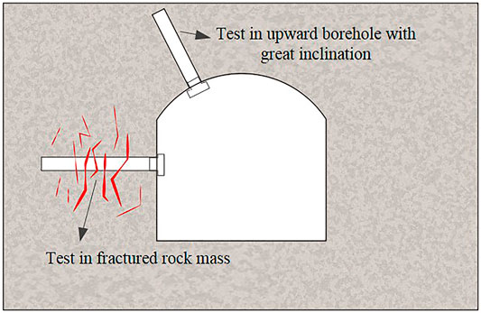
FIGURE 2. Limitations of acoustic test in determining excavation damage zone.
Digital borehole televiewers can intuitively reflect the drilling geological characteristics of surrounding rock from borehole, and more importantly, the test method has strong anti-interference immunity from the influence of environmental change. As shown in the engineering case, the position of crack initiation and expansion obtained from digital borehole televiewers corresponds with acoustic wave velocity descent (Figure 3), even in some visible fractures of rock mass, where the results of the acoustic test are unable to accurately determine the location of the crack (Figure 4).
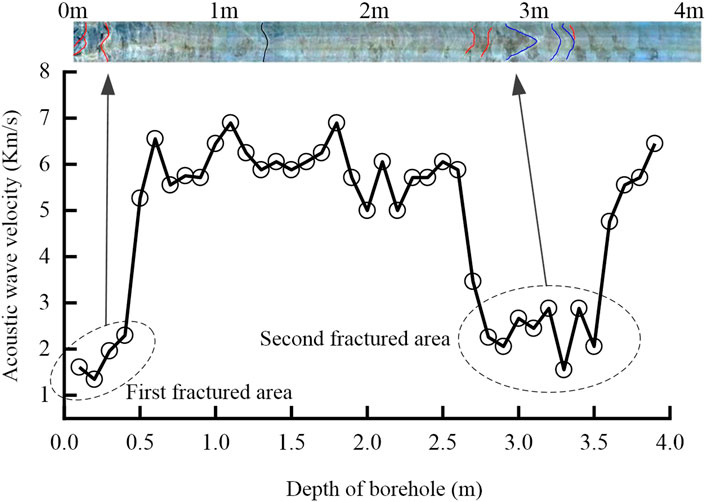
FIGURE 3. Test in area with several fractured zone.
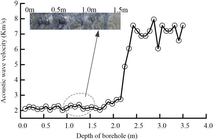
FIGURE 4. Visible fracture of rock mass from digital borehole televiewers.
Evaluation Method of Rock Mass Damage Based on Surrounding Rock Damage-Fracture Ratio
3.1 Definition and parameters of surrounding rock damage-fracture ratio
Testing practices in deep underground engineering show that there is local similarity in the depth of the excavation damage zone and highly damaged zone (Sun et al., 2021). Surrounding rock damage-fracture ratio (R) is defined as the depth of excavation damage zone to the depth of the highly damaged zone. That is,
Obviously, R is a dimensionless quantity and directly related to the excavation damage zone and highly damaged zone of the surrounding rock. Guo et al. (2017) put forward the rock mass integrity index (RMIBT) (by measuring the proportion of rock mass without macroscopic fissures in the borehole wall) based on digital borehole televiewer; it can be used to characterize the relation of the rock mass integrity and damage or fracture state of rock mass. It was applied in multiple deep rock excavations and proved to be useful. In addition, the RMIBT can be used to dynamically assess the integrity of macroscopic rock masses and the evolution of fractures in the excavation damaged zone.
The most common damage zone theoretical model showed the damage area affected by the stress conditions in the deep surrounding rock mass (Martin et al., 1999). Richards and Bjorkman, (1978) emphasized the influence of excavation shape and size on the development of the surrounding rock damage. Given the test data, we considered the excavation span along the damaged direction without the effect of shape.
Mathematical Model for R
Dimensional analysis, which is often used in the mathematical model of complex engineering problems, is adopted to determine the mathematical expression of R affected by multiple factors.
It involves the principal stress difference of stress field σ1-σ3, the rock mass integrity index RMIBT, the excavation span along the damaged direction B, the depth of excavation damage zone HEDZ, and the highly damaged zone HHDZ, then,
Dimensions for each control variable are:
K as the objective function of the dimensional matrix, and,
Solving zero space for matrix K,
Therefore, the dimensionless factors are
Determination of the Parameters in R
With better integrity of the surrounding rock, the depth of the excavation damage zone (HEDZ) and the highly damaged zone (HHDZ)can be obtained by acoustic test and digital borehole televiewers. The established model should meet the requirement that there is a very small difference between the calculated value and the measured value:
The test data were shown in Table 1; the appropriate relation and suitable parameters can be derived from the engineering practice.

TABLE 1. Test data in Baihetan engineering practice.
Using a hybrid explicit and implicit algorithm, the expression of R can be shown in the following form:
In which R is the surrounding rock damage-fracture ratio, HHDZ is the depth of highly damaged zone, RMIBT is the rock mass integrity index, and they can be determined by digital borehole televiewer. B is the excavation span along the damaged direction. According to the test data from the engineering practice, the parameters bi are b1 = 1.7015, b2 = −0.1532, b3 = −0.1419.
The Error Analysis
Comparing the measured R from different rock mass integrity conditions with the calculated value, the error analysis is shown in Figure 5. The error between measured data and calculated data is relatively small both in good or bad integrity conditions. However, in the area with low strength or with already released stress, the depth of excavation damage zone and highly damaged zone are close to each other, and the calculated EDZ is obtained from calculated R of greater safety reserves.
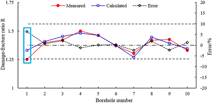
FIGURE 5. Error analysis of the proposed method.
Compared with the acoustic test, the proposed method, considering the integrity of rock mass and excavation span of surrounding rock, is only dependent on the results of borehole camera which has strong anti-interference and applicability.
Engineering Practice
The test data were obtained from famous deep underground engineering. After evaluating the integrity of the surrounding rock mass using the RMIBT method proposed by Guo et al. (2017), the surrounding rock masses were divided into intact rock (RMIBT≥0.5) and broken rock (RMIBT<0.5), as shown in Figure 6. Twenty randomly selected boreholes in the cavern with 14 m excavation spans were used as training samples to solve the coefficient in the model, and two boreholes, T4-2 and T7-4, were used as test samples to validate the calculation model.
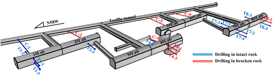
FIGURE 6. Drilling arrangement in engineering case.
The lithology of the surrounding rock mass in T4-2 is polychromatic marble. The observation results in Figure 7 showed that the depth of the highly damaged zone is 1.8 m with an integrity index RMIBT 0.568. The acoustic test showed 2.6 m for the excavation damage zone, so the test surrounding rock damage-fracture ratio of the surrounding rock is 1.4, while the calculated damage-fracture ratio of the surrounding rock is 1.45.
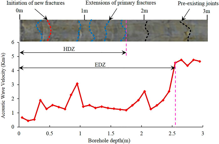
FIGURE 7. Test result in borehole T4-2.
The lithology of the surrounding rock mass in T7-4 is grey marble. The observation results in Figure 8 showed that the depth of the highly damaged zone is 0.6 m with an integrity index RMIBT of 0.75. The acoustic test showed 1.2 m for the excavation damage zone, so the test damage-fracture ratio of the surrounding rock is 2.0 while the calculated ratio is 2.07, and there is little difference between the calculated value and the measured value.
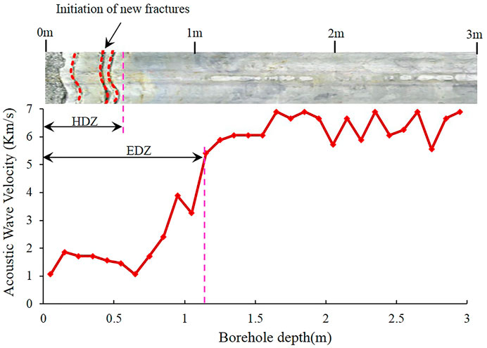
FIGURE 8. Test result in borehole T7-4.
The calculated values of the T4-2 and T7-4 are basically consistent with the acoustic test values, which indicates that the established model of the surrounding rock damage-fracture ratio R can be used to evaluate the depth of EDZ under different surrounding rock integrity conditions.
Discussion
The applicability of this method has been verified to be good. It is worth noting that when the method is used independently, as several parameters involved in the calculation model are obtained from field tests, the values of the parameters are highly susceptible to affecting the accuracy of the calculation results, and in order to clearly understand the influence of these parameters on the calculated value, a parameter sensitivity analysis was performed on the recommended surrounding rock damage-fracture ratio model.
Variance-based sensitivity analysis, often referred to as the Sobol method (Sobol, 2001), is a form of global sensitivity analysis that can handle nonlinear effects. The calculation results are relatively robust and reliable. It has been widely used in sensitivity analysis of large nonlinear models in environmental and economic fields. In this method, the total variance of the model can be decomposed into a combination of individual parameters and multiple parameter interactions.
Where D is the total variance of the model.
Normalizing the above equation, the sensitivity of the model to each parameter and the correlation of each parameter can be achieved.
Then the Total-effect index of the model can be expressed as,
First-order index
Total-effect index
The global sensitivity analysis of the damage-fracture ratio R of the surrounding rock was carried out, and the sampling was carried out according to the range of the independent variables, and the sampling method was adopted by the Monte Carlo method. 40,000 sets of model parameters were randomly selected, and the calculation results tended to converge after the calculation. The results of the first-order index and total-effect index of the parameters are shown in Table 2 below.
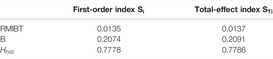
TABLE 2. Results of the sensitivity analysis.
The results showed that the damage-fracture ratio R is more influenced by the depth of the highly damaged zone than the integrity of rock mass. And the total sensitivity of the parameters does not differ much from the first-order sensitivity, which indicates that the model is immune from the multiple parameter interactions.
In this model, several parameters were obtained from the engineering practice based on the available data. In fact, it is also feasible to select other characteristic parameters, such as principal stress ratio, strength stress ratio, and high-span ratio, to establish the model. However, it is not advisable to use more parameters, because too many parameters will make it difficult to determine the special solution of matrix zero space, thus introducing more influencing factors. On the other hand, more parameters may make the calculation results satisfactory at the expense of the applicability of the method in engineering. After all, construction workers are not good at performing complex calculations and error analysis of the results.
Conclusion
An acoustic wave test is still a commonly used method to determine the excavation damage zone (EDZ) because of its low cost and easy implementation. However, the performance of the method is negatively affected by the drilling environment and the fracture of the rock mass.
This paper proposed a method that takes into account the in-situ stress, rock mass integrity, span length, and depth of highly damaged zone to overcome these effects for reliable determination of EDZ. First, surrounding rock damage-fracture ratio (R) is defined as the depth of the excavation damage zone to the depth of the highly damaged zone. Multiple factors were summarized from the existing research results of surrounding rock damage as the dominant influence. Then, the dimensional analysis method was employed to generate an implicit expression. To determine the impact of selected parameters on the results, the parameter sensitivity analysis was demonstrated. For better practicality, different deep engineering case data were verified in the proposed method. The results prove that the proposed method is remarkably successful in the determination of EDZ evaluation of deep buried engineering projects, and also has strong anti-noise capability due to the independence of the acoustic test.
Data Availability Statement
The original contributions presented in the study are included in the article/Supplementary Material, further inquiries can be directed to the corresponding author.
Author Contributions
Investigation, HG and JT; methodology, HG and QS, writing—original draft preparation, HG and QS; writing—review and editing, HG and QS; data curation, HG and WL. All authors have read and agreed to the published version of the manuscript.
Funding
This study was funded by the National Natural Science Foundation of China (Grant No. 51978265, 51909136), and the Open Research Fund of Key Laboratory of Geological Hazards on Three Gorges Reservoir Area (China Three Gorges University), Ministry of education, Grant number 2020KDZ03.
Conflict of Interest
The authors declare that the research was conducted in the absence of any commercial or financial relationships that could be construed as a potential conflict of interest.
The reviewer YF declared a shared affiliation the author XY, to the handling editor at the time of the review.
Publisher’s Note
All claims expressed in this article are solely those of the authors and do not necessarily represent those of their affiliated organizations, or those of the publisher, the editors and the reviewers. Any product that may be evaluated in this article, or claim that may be made by its manufacturer, is not guaranteed or endorsed by the publisher.
References
Baechler, S., Lavanchy, J. M., Armand, G., and Cruchaudet, M. (2011). Characterisation of the Hydraulic Properties within the Edz Around Drifts at Level 490 M of the Meuse/haute-marne Url: a Methodology for Consistent Interpretation of Hydraulic Tests. Phys. Chem. Earth Parts A/b/c 36 (17-18), 1922–1931. doi:10.1016/j.pce.2011.10.005
Eberhardt, E., and Diederichs, M. (2012). Review of Engineering Geology and Rock Engineering Aspects of the Construction of a KBS-3 Repository at the Forsmark Site—Initial Review Phase. Stockholm: Swedish Radiation Safety Authority.
Fan, Y., Lu, W. B., Yan, P., Chen, M., and Zhang, Y. Z. (2015). Transient Characters of Energy Changes Induced by Blasting Excavation of Deep-Buried Tunnels. Tunnelling Underground Space Tech. 49, 9–17. doi:10.1016/j.tust.2015.04.003
Fan, Y., Zheng, J. W., Cui, X. Z., Leng, Z. D., Wang, F., and Lv, C. C. (2021). Damage Zones Induced by In Situ Stress Unloading during Excavation of Diversion Tunnels for the Jinping II Hydropower Project. Bull. Eng. Geology. Environ. 2021 (8), 1–27. doi:10.1007/s10064-021-02172-y
Feng, G.-L., Chen, B.-R., Xiao, Y.-X., Jiang, Q., Li, P.-X., Zheng, H., et al. (2022). Microseismic Characteristics of Rockburst Development in Deep TBM Tunnels with Alternating Soft-Hard Strata and Application to Rockburst Warning: A Case Study of the Neelum-Jhelum Hydropower Project. Tunnelling Underground Space Tech. 122, 104398. doi:10.1016/j.tust.2022.104398
Feng, G.-L., Feng, X.-T., Chen, B.-r., Xiao, Y.-X., and Yu, Y. (2015). A Microseismic Method for Dynamic Warning of Rockburst Development Processes in Tunnels. Rock Mech. Rock Eng. 48 (5), 2061–2076. doi:10.1007/s00603-014-0689-3
Guo, H.-S., Feng, X.-T., Li, S.-J., Yang, C.-X., and Yao, Z.-B. (2017). Evaluation of the Integrity of Deep Rock Masses Using Results of Digital Borehole Televiewers. Rock Mech. Rock Eng. 50 (6), 1371–1382. doi:10.1007/s00603-017-1173-7
Harrison, J., Hudson, J., and Popescu, M. (2002). Engineering Rock Mechanics: Part 2. Illustrative Worked Examples. Appl. Mech. Rev. 55 (2). doi:10.1115/1.1451166
Huang, F., Zhu, H. H., Li, Q. S., and Li, E-P. (2016). Field Detection and Theoretic Analysis of Loose circle of Rock Mass Surrounding Tunnel. Rock Soil Mech. 37, 145–150. doi:10.16285/j.rsm.2016.S1.019
Jing, H., W, , Fu, G. B., and Guo, Z. (1999). Measurement and Analysis of Influential Factors of Broken Zone of Deep Roadways and Study on its Control Technique. Chin. J. Rock Mech. Eng. 18 (1), 70–74.
Kelsall, P. C., Case, J. B., and Chabannes, C. R. (1984). Evaluation of Excavation-Induced Changes in Rock Permeability. Int. J. Rock Mech. Mining Sci. Geomechanics Abstr. 21 (5), A177. doi:10.1016/0148-9062(84)91530-4
Malmgren, L., Saiang, D., Töyrä, J., and Bodare, A. (2007). The Excavation Disturbed Zone (EDZ) at Kiirunavaara Mine, Sweden-by Seismic Measurements. J. Appl. Geophys. 61, 1–15. doi:10.1016/j.jappgeo.2006.04.004
Martin, C. D., Kaiser, P. K., and McCreath, D. R. (1999). Hoek-Brown Parameters for Predicting the Depth of Brittle Failure Around Tunnels. Can. Geotech. J. 36 (1), 136–151. doi:10.1139/t98-072
Pusch, R., and Stanfors, R. (1992). The Zone of Disturbance Around Blasted Tunnels at Depth. Int. J. Rock Mech. Mining Sci. Geomechanics Abstr. 29 (5), 447–456. doi:10.1016/0148-9062(92)92629-q
Richards, R., and Bjorkman, G. S. (1978). Optimum Shapes for Unlined Tunnels and Cavities. Eng. Geology. 12, 171–179. doi:10.1016/0013-7952(78)90010-8
Sato, T., Kikuchi, T., and Sugihara, K. (2000). In-situ Experiments on an Excavation Disturbed Zone Induced by Mechanical Excavation in Neogene Sedimentary Rock at Tono Mine, central Japan. Eng. Geology. 56, 97–108. doi:10.1016/s0013-7952(99)00136-2
Siren, T., Kantia, P., and Rinne, M. (2015). Considerations and Observations of Stress-Induced and Construction-Induced Excavation Damage Zone in Crystalline Rock. Int. J. Rock Mech. Mining Sci. 73, 165–174. doi:10.1016/j.ijrmms.2014.11.001
Sobol, I. M. (2001). Global Sensitivity Indices for Nonlinear Mathematical Models and Their Monte Carlo Estimates. MATH. COMPUT. SIMULAT 55 (1–3), 271–280. doi:10.1016/S0378-4754(00)00270-6
Sun, Q. C., Zheng, M. Z., Li, S. J., Guo, H-S., Cheng, Y., Pei, S-F., et al. (2019). Variation Characteristics and Determination of Tunnel Relaxation Depth of Columnar Jointed Rock Mass. Rock Soil Mech. 40 (2), 728–736. doi:10.16285/j.rsm.2017.1616
Sun, Q., Li, S., Guo, H., Zheng, M., and Yang, Z. (2021). In Situ test of Excavation Damaged Zone of Columnar Jointed Rock Masses under Different Borehole Conditions. Bull. Eng. Geol. Environ. 80 (4), 2991–3007. doi:10.1007/s10064-020-02100-6
Wu, F. Q., Liu, J. Y., Liu, T., Zhuang, H., and Yan, C. (2009). A Method for Assessment of Excavation Damaged Zone (EDZ) of a Rock Mass and its Application to a Dam Foundation Case. Eng. Geology. 104 (3), 254–262. doi:10.1016/j.enggeo.2008.11.005
Xie, H. P., Gao, F., and Ju, Y. (2015). Research and Development of Rock Mechanics in Deep Ground Engineering. Chin. J. Rock Mech. Eng. 34 (11), 2161–2178. doi:10.13722/j.cnki.jrme.2015.1369
Yang, J., Dai, J., Yao, C., Jiang, S., Zhou, C., and Jiang, Q. (2020). Estimation of Rock Mass Properties in Excavation Damage Zones of Rock Slopes Based on the Hoek-Brown Criterion and Acoustic Testing. Int. J. Rock Mech. Mining Sci. 126, 104192. doi:10.1016/j.ijrmms.2019.104192
Yu, Y., Feng, G.-l., Xu, C.-j., Chen, B.-r., Geng, D.-x., and Zhu, B.-t. (2022). Quantitative Threshold of Energy Fractal Dimension for Immediate Rock Burst Warning in Deep Tunnel: A Case Study. Lithosphere 2021, 1699273. doi:10.2113/2021/1699273
Zhou, X. P., and Qian, Q. H. (2007). Zonal Fracturing Mechanism in Deep Tunnel. Chin. J. Rock Mech. Eng. 26 (5), 877–885. doi:10.1016/S1872-2067(07)60020-5
Keywords: damage-fracture ratio, excavation damage zone, highly damaged zone, underground engineering, surrounding rock
Citation: Guo H, Tong J, Sun Q, Yang X, Luo W and Yu Y (2022) Determination Method of Excavation Damage Zone Based on Surrounding Rock Damage-Fracture Ratio in Underground Engineering. Front. Earth Sci. 10:836313. doi: 10.3389/feart.2022.836313
Received: 15 December 2021; Accepted: 21 February 2022;
Published: 07 April 2022.
Edited by:
Shibing Huang, Wuhan University of Science and Technology, ChinaReviewed by:
Yi Luo, Wuhan University of Technology, ChinaYong Fan, China Three Gorges University, China
Yangyi Zhou, Northeastern University, China
Copyright © 2022 Guo, Tong, Sun, Yang, Luo, Yu. This is an open-access article distributed under the terms of the Creative Commons Attribution License (CC BY). The use, distribution or reproduction in other forums is permitted, provided the original author(s) and the copyright owner(s) are credited and that the original publication in this journal is cited, in accordance with accepted academic practice. No use, distribution or reproduction is permitted which does not comply with these terms.
*Correspondence: Qiancheng Sun, qc_sun@ctgu.edu.cn