Biomimetic, antiadhesive surface structure inspired by the calamistra setae of cribellate spiders for electrospun nanofiber handling
 Sebastian Lifka1*
  Christoph Stecher1
  Marco Meyer2
  Anna-Christin Joel2
  Johannes Heitz3
  Werner Baumgartner1
- 1Institute of Biomedical Mechatronics, Johannes Kepler University Linz, Linz, Austria
- 2Institute of Biology II, RWTH Aachen University, Aachen, Germany
- 3Institute of Applied Physics, Johannes Kepler University Linz, Linz, Austria
Introduction: Due to their excellent surface-to-volume ratio, nanofibers (i.e., fibers with a diameter of approximately 10 to 800 nm) are of increasing interest to engineers and scientists in a broad spectrum of applications. However, due to van der Waals forces, these nanofibers tend to adhere strongly to any surface, which makes further processing very challenging. In nature, we find animals that can easily handle nanofibers: Cribellate spiders use a comb-like structure, the so-called calamistrum, to produce, handle, and process nanofibers. Due to a fingerprint-like surface nanostructure, nanofibers do not adhere to the calamistrum. The principle interaction between this fingerprint-like surface nanostructure and single nanofibers has recently been described in a publication. The fingerprint-like surface structure was replicated on a technical metal surface using laser-induced periodic surface structures, which resulted in material properties resembling those of the natural model.
Methods: We went a step further and took a closer look on an additional structural feature of the calamistrum much larger than the fingerprint-like surface structure. A theoretical approach to describing the influence of a fiber preload, which may become a dominant effect if the fiber dimensions are small compared to the surface structure dimensions, on the adhesion of the fiber to these large surface structures was derived. Our theory was verified experimentally for artificial electrospun polyamide 6 nanofibers on surface-structured samples made of titanium alloy.
Results and Conclusion: A dramatic reduction in adhesion compared to unstructured, flat surfaces was proven. Therefore, such a surface structure can be used for tools or parts of tools during nanofiber production (e.g., as part of the electrospinning process) to reduce the adhesion of the nonwoven fabric and thus facilitate the handling and processing of the nanofibers during production.
1. Introduction
The electrospinning process (Ramakrishna et al., 2006; Akampumuza et al., 2017; SalehHudin et al., 2018) is rapidly evolving in various directions, such as from the single-fluid process (Hameed et al., 2022) to coaxial (Jiang et al., 2022), tri-axial (Liu Y. et al., 2022), side-by-side (Xu et al., 2022) and other complicated processes (Liu H. et al., 2022), and the combination of electrospinning with traditional chemical and physical methods (Du et al., 2022). These developments have greatly promoted the applications of electrospun nanofibers in a wide variety of fields such as medicine (Wu et al., 2017), filtration (Avossa et al., 2021), textile (Gorji et al., 2012), battery (Zhang et al., 2016) and fuel cell (Yusoff and Shaari, 2021) manufacturing, and optical sensor fabrication (Wang et al., 2002). However, very limited attention has been paid to a key issue for application, this is, anti-adhesion of electrospun nanofibers on the subject’s surfaces, which is also useful for developing a fine fibrous collector. The adhesion of nanofibers to any surface is mainly due to so-called van der Waals forces (Parsegian, 2005).
In nature, there are animals that are capable of efficiently producing, processing, and handling nanofibers: cribellate spiders. For this the spiders use the so-called calamistrum, a comb-like structure of modified setae (hairs) on the metatarsus (mid-foot) of the hind (fourth) legs, to which the 10–30 nm thick silk nanofibers do not adhere due to a special fingerprint-like surface nanostructure (Joel et al., 2020).
In a recent work we have shown theoretically and experimentally that the fingerprint-like structures can in fact reduce adhesion due to van der Waals forces. As shown in Lifka et al. (2022) we could derive a theoretical model of the interaction of a fiber with a surface exhibiting a sinusoidal topography, which can be used to describe the interaction of native spider fibers with the calamistrum or artificial electrospun fibers with artificial surfaces. The theory shows that the energy due to bending of the fibers is the dominant antiadhesive effect for small-sized surface structures, more precisely, when the size of the structures is of the order of the fiber diameter. For larger structures (i.e., “large” compared to the fiber diameter) the effect of an eventually present longitudinal force (i.e., fiber preload) might become a dominant effect and in that case the bending stiffness of the fiber may be neglected.
In nature, an additional structural feature of the calamistrum, which is much larger than the fingerprint-like nanostructure can be observed. In presence of such a fiber preload, these larger surface structures may decrease the adhesion of the fibers to the calamistrum even more. As electrospun fibers typically shrink during polymerization (Yuan, 2021), such a fiber preload can also be assumed in the electrospinning process. The polymerization is not completely finished when the fiber hits the target electrode, thus the initial elastic modulus is rather low and even in contact with the target some shrinkage occurs leading to a longitudinal force (i.e., fiber preload). Therefore, an appropriate surface-structured electrospinning target may reduce the adhesion of the fibers to the target surface, which would allow an easy removal of the electrospun nanofiber nonwoven from the target electrode and would be beneficial for the production, handling, and processing of nonwoven nanofiber fabric.
In this work we present a theoretical approach to describe the influence of a fiber preload onto the adhesion on surface structures inspired by the calamistrum of Uloborus plumipes, that are much larger than typical fiber diameters. The results were verified experimentally by measuring the peel-off forces of the electrospun nonwoven on surface-structured samples and on flat (control) samples made of titanium alloy. We found a dramatic reduction in adhesion for electrospun nanofibers on technical surface structures compared to complete flat surfaces, matching the theory derived here.
2. Results
2.1. Setae forming large scale structures as natural model
As can be seen in Figures 1A, a calamistrum of Uloborus plumipes consists of individual setae (hairs). These setae are covered by the initially mentioned fingerprint-like nanostructure. However, the individual setae have a flattened diameter, instead of a roundish one (which would be typical for setae). They are not perfectly aligned on a plane, but arranged in an imbricated way, where the cross section of each hair can be approximated by a triangle or saw-tooth shape (Figures 1B,C). They typically measure several micrometers and are thus much larger than the fingerprint-like structures. A hierarchical surface structure, similar to the Lotus effect (Barthlott and Neinhuis, 1997; Koch et al., 2009), consisting of the fingerprint-like nanostructures on the small scale and the shape as well as assembly of the setae on a larger scale, can therefore be assumed. Both may reduce adhesion even more.
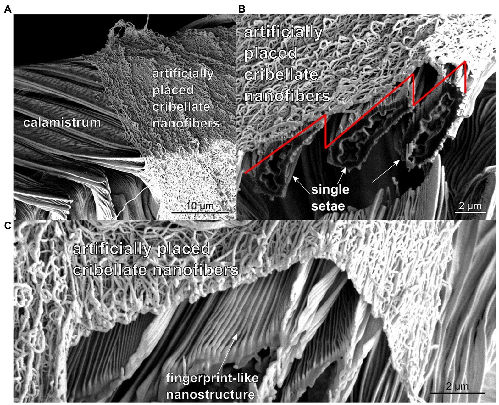
Figure 1. (A) SEM-image of the calamistrum of the feather-legged lace weaver Uloborus plumipes, with artificially placed cribellate nanofibers on top of it before cutting with focused ion beam (FIB). (B) SEM-image of the calamistrum after FIB cutting. The single setae can be abstracted as triangles (indicated by red line), which are overlapping each other in the final comb. (C) Further magnified SEM-image of the calamistrum after FIB cutting, in which the fingerprint-like nanostructure on the individual setae can be seen. The nanofibers are predominantly resting on the tips of these triangles.
As the spiders continuously brush over the nanofibers with the calamistrum for extraction (Joel et al., 2015) and in movies the assembled threads can be seen under tension during extraction, we also assume the nanofibers to be extracted under tension (Joel et al., 2016). Therefore, a longitudinal force, − that is., a preload of the fibers in the natural model–can be assumed. Unfortunately, a measurement of this longitudinal force during nanofiber production is not possible.
2.2. Theoretical modelling
In order to describe the adhesion phenomena on these large-scale surface structures in the presence of a longitudinal fiber force, a theoretical approach is presented below using the principle of virtual work (Ziegler, 1992).
Let us assume the fiber to be thin in comparison to the dimensions of the surface structures, more precisely, the fiber diameter is small compared to the surface structure dimensions. Thus, we can approximate the fiber as a rope, that is, a structure that can bear longitudinal stress but has no bending stiffness. In contrast to the theoretical model presented in Lifka et al. (2022), where the bending stiffness of the fiber must not be neglected as the fiber diameter is in the same order as the above-mentioned fingerprint-like surface nanostructure. Furthermore, we assume a very simple triangular surface structure derived from the natural model Uloborus plumipes depicted in Figure 2.
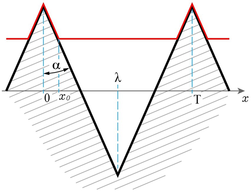
Figure 2. Surface geometry and principle of the fiber-surface interaction. The surface (black line) comprises a symmetric triangular shape that is periodic along the x-axis. It is characterized by a distance λ from top to bottom along the x-axis and the half-angle of the triangles α. The fiber (red line) is flexible towards bending and adheres to the surface towards a position x0.
The surface structure has a distance from top to bottom of λ and is periodic and symmetric along the x-coordinate. The half-angle of the triangles is α and the fiber, assumed to be a rope and thus to be flexible towards bending, is in contact to the surface towards a position x0. Due to the periodicity and symmetry, it is sufficient to describe the conditions in the region x = 0...λ.
Initially the fiber aligns due to the spinning process to the surface. Thus, the total length of the initial fiber directly after the spinning shall be denoted l0. If the fiber sticks to the whole profile, the length l0 on the region x = 0...λ is
Now, due to polymerization or cooling the fibers tend to shrink which would lead to the unstresses length
Here, ξ = 1–s with s denoting the shrinkage is the length ratio after shrinkage (i.e., a value smaller 1). At the equilibrium the total energy Etot in the system tends to a minimum. This energy is given by the sum of the adhesive energy Ead due to van der Waals interaction and the elastic energy Eel stored in the fiber under stress. The adhesive energy is simply given by
with μ denoting the energy per unit length. The first equality is a general statement whereas the second is valid only in our case of the triangular geometry depicted above. The force F acting on the fiber in contact with the structure from 0 to a given x0 is
with σ denoting the stress, A denoting the cross section of the fiber, ε denoting the strain, and E denoting the elastic modulus of the fiber. Here, l is the total length of the fiber from x = 0 to x = λ, with l > lu, which equals
To obtain the yet unknown parameter x0 we can apply the principle of virtual work (Ziegler, 1992). In the equilibrium an infinitesimal but arbitrary shift from the equilibrium position (e.g., a small shift of the contact point x0 by δx0) will not perform work
The change in length of the fiber δl0 can be calculated from δx0 as
This leads to
As this must be valid for any δx0 we obtain
Solving Equation 9 for x0 yields
Dividing by λ yields
This means that the portion of the surface x0/λ where adhesive contact of the fiber takes place is only dependent on three main parameters:
The shrinkage, described by the factor ξ, which is 1 if no shrinkage occurs,
the ratio of adhesive energy per unit length μ and the stiffness of the fiber described by EA,
and sin(α), representing the surface geometry.
It has to be emphasized that the results of Equation 11 must be clipped at 0 and 1 to be physically meaningful. To get a sense of the order of magnitude of μ/EA, a rough estimate must be made. For a cylindrical fiber with radius R in combination with a plane surface of a simi-infinite body the energy per unit length due to van der Waals interaction for d < < R is given as (Parsegian, 2005)
with AH denoting the so-called Hamaker constant, and d denoting the distance between the fiber and the surface. The Hamaker constant of polyamide 6 (PA6), which is used for electrospinning in this work, across vacuum is approximately APA6/PA6 = 12⋅10−20 J (Duleba et al., 2014) and the Hamaker constant of titanium (Ti) across vacuum is approximately ATi/Ti = 18⋅10−20 J (Eichenlaub et al., 2002; Parsegian, 2005). According to Parsegian (2005) the Hamaker constant AH between PA6 and Ti can then be calculated as follows
Assuming R = 60 nm and d = 0.1 nm, μ results in 1.54⋅10−8 J/m. The elastic modulus of a PA6 nanofiber is assumed to be approximately E = 1 GPa (Bazbouz and Stylios, 2010), which results in a stiffness EA of the fiber of 1.13⋅10−5 N. The ratio μ/EA for the setup used in this work can therefore be approximated as μ/EA ≅ 10−3. As the polymerization is not completely finished when the fiber hits the target and thus the initial elastic modulus is even lower, and therefore the initial ratio μ/EA is even larger.
In Figure 3, the behavior of x0 /λ, which is a measure for the interaction of the fiber with the surface, is depicted in dependence on the above-described parameters. In accordance with the calculations above, ratios of μ/EA ranging from 10−5 to 10−1 are shown. Not surprisingly, the ratio μ/EA has a huge influence. Generally, the higher the van der Waals interaction (the higher μ), the stronger the contact and thus the more the ratio x0/λ tends towards 1. Higher stiffness of the fiber (i.e., higher EA) yields less contact. The higher the shrinkage, the less adhesive interaction, this can be observed for angles α larger than 0° and smaller than 90°. If the surface is flat or consists of extremely steep walls, in other words, has an extraordinary aspect ratio, shrinkage has no strong effect as obvious from geometrical considerations.
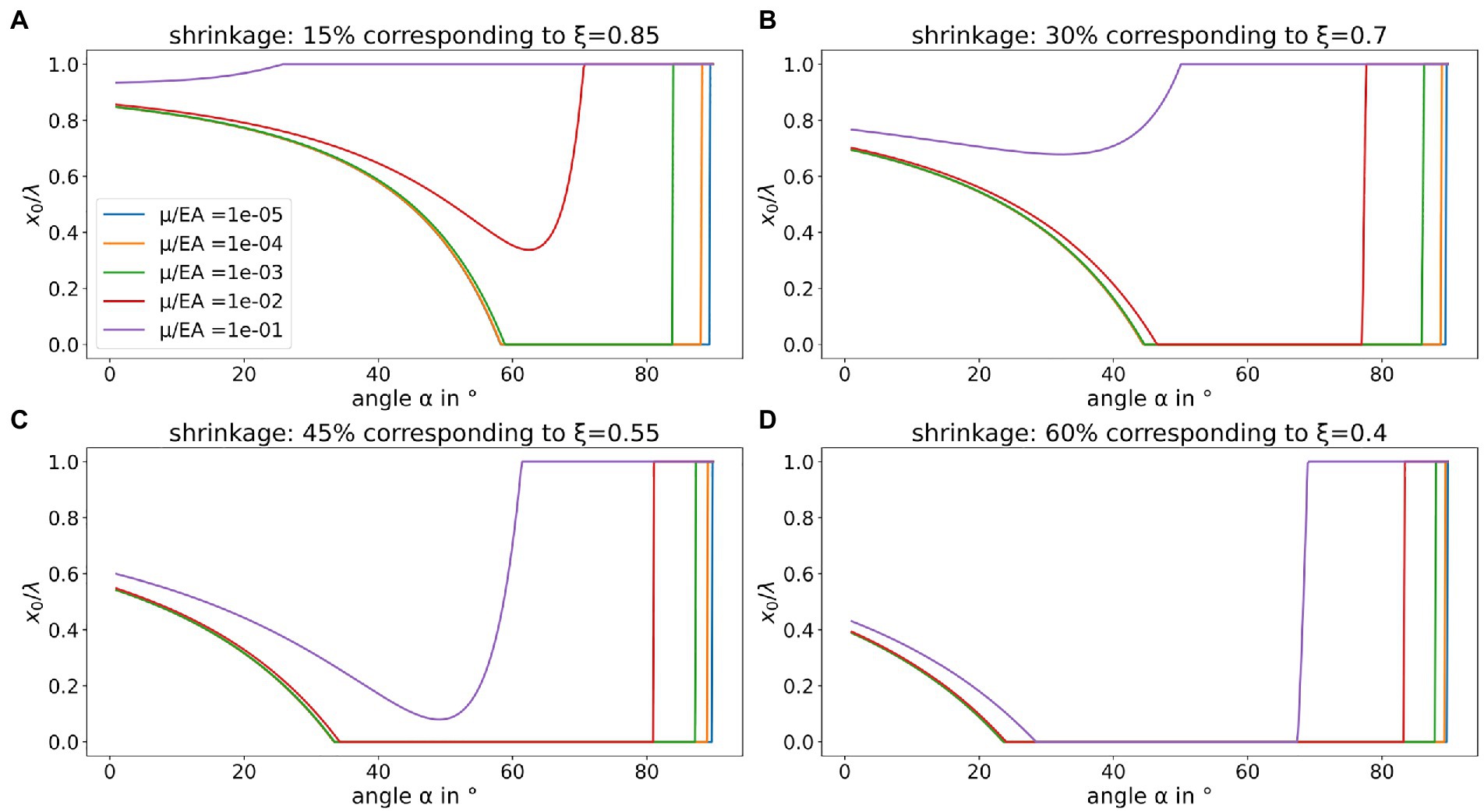
Figure 3. Adhesive contact in dependence on shrinkage, surface geometry, adhesive interaction, and fiber stiffness. A ratio x0/λ = 1 means full adhesive contact of the fiber and the surface geometry given, whereas x0/λ = 0 means that the fiber only touches the tips of the triangular surface geometry. The individual panels show the behavior for different values of shrinkage: (A) 15% shrinkage, (B) 30% shrinkage, (C) 45% shrinkage, and (D) 60% shrinkage. The ratio μ/EA ranging from 10−5 to 10−1 is identically color-coded in every panel. To be physically meaningful, the ratio x0/λ has to be clipped between 0 and 1.
As one can see in Supplementary Figure S1 (Supplementary material), which shows a scanning electron microscope (SEM)-image of nonwoven layer produced by the electrospinning setup, the fibers are oriented randomly, which means that not every fiber is oriented orthogonally to the triangular shape direction as it is assumed in the theoretical model. However, the cross section of the surface structure shape under a different fiber angle β is still triangular, but with different tip spacing λeff ≥ λ and tip angle αeff ≥ α. Thus, the theory is still valid. The effective tip angle αeff for a given tip angle α under different fiber angles 0° ≤ β < 90° can be calculated from geometrical considerations as follows
To get an idea of the mean effective tip angle , the integral mean over 0° ≤ β < 90° from Equation 14
has to be calculated for a given α.
Now, Figure 4 shows the behavior of x0 /λ in dependence on the above-described parameters in consideration of a mean effective tip angle like described above. If one compares Figure 3 with Figure 4, one notices that at high shrinkages the ratio x0 /λ increases continuously from a certain value of α with increasing α, which is not the case when neglecting the mean effective angle . This in turn means that especially at higher shrinkages and less stiff fibers there is a clear minimum of the ratio x0 /λ, which for example at 45% shrinkage is at an angle α of about 35°.
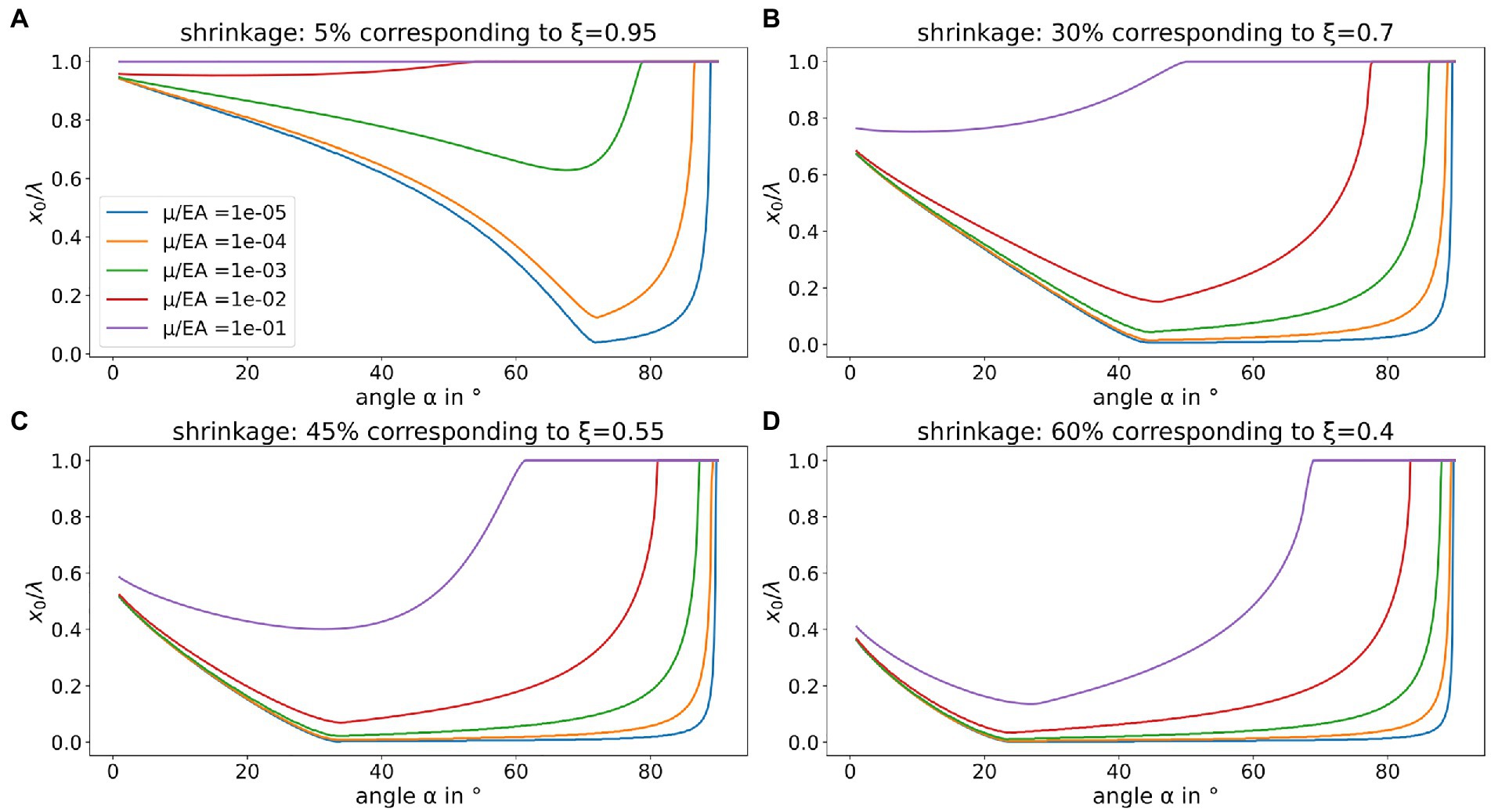
Figure 4. Adhesive contact in dependence on shrinkage, surface geometry, adhesive interaction, and fiber stiffness under consideration of a mean effective angle as the fiber is not necessarily orthogonal to the surface geometry. A ratio x0/λ = 1 means full adhesive contact of the fiber and the surface geometry given, whereas x0/λ = 0 means that the fiber only touches the tips of the triangular surface geometry. The individual panels show the behavior for different values of shrinkage: (A) 15% shrinkage, (B) 30% shrinkage, (C) 45% shrinkage, and (D) 60% shrinkage. The ratio μ/EA ranging from 10−5 to 10−1 is identically color-coded in every panel. To be physically meaningful, the ratio x0/λ has to be clipped between 0 and 1.
Now, the exact geometry that reduces the adhesion of the electrospun nonwoven remains to be determined. The simple theory above would predict that only the angle α determines the interaction energy and thus the adhesion, if the material, in particular the shrinking, is defined. However, as initially mentioned a fact that is not explicitly introduced into the theory is that due to deformation of the fibers at the tips of the surface structure a little bit of van der Waals interaction is generated. The total amount is dependent on the number of interaction points per unit length and thus inverse proportional to the periodicity T. More explicitly, even if the tips are really pointed, which in real life will never happen, due to Hertzian pressure a little deformation of the fiber will always happen and thus there is a small length a at each tip where van der Waals interaction takes place. The period length T is then given as T = a + b, where b is the length of the free (non-interacting) fiber. The interaction energy due to this tip-interaction per unit length is thus given as
Therefore, it seems that it is favorable to have as large spacing b as possible in order to minimize the interaction, especially if the tips are not “infinitely tipped.” However, there is a natural limit to the tip spacing. At a certain point during the electrospinning process bending instabilities take place causing the jet path to become “curly” due to higher order bending instabilities (Reneker and Fong, 2005; SalehHudin et al., 2018). Let us define a characteristic length L which is a length where the fiber can be assumed to be a straight line. If the spacing T (T = a + b) is significantly larger than this characteristic length, the above theory is not valid anymore, as the assumptions are violated. Thus, there is an upper limit of the spacing which is given by the characteristic length of the electrospun fibers. An analytic calculation of this characteristic length appears to be very challenging as the dynamically changing material properties of the polymerizing fiber and the viscous properties of the surrounding atmosphere must be considered. However, it can be simply estimated from SEM-images of the nonwoven.
2.3. Design of surface-structured titanium alloy samples that are antiadhesive for electrospun PA6 fibers
PA6 fibers keep their crude direction for several tens of μm. Thus, we decided to produce a surface with a triangular shape with 30° slope, as for materials with shrinkage >45% this angle seems to be beneficial according to the theoretical results shown in Figures 3, 4. The tip spacing was chosen to be approximately 250 μm, as we thought this to be large enough to reduce the tip-energy given in Equation 16 and small enough in comparison to the characteristic length of the fibers. The depth of the structure is about 200 μm. In Figure 5A photography of a surface-structured Ti alloy sample is depicted. Figures 5B–D show SEM-images of the surface-structured Ti alloy specimen (top-view and cross section).
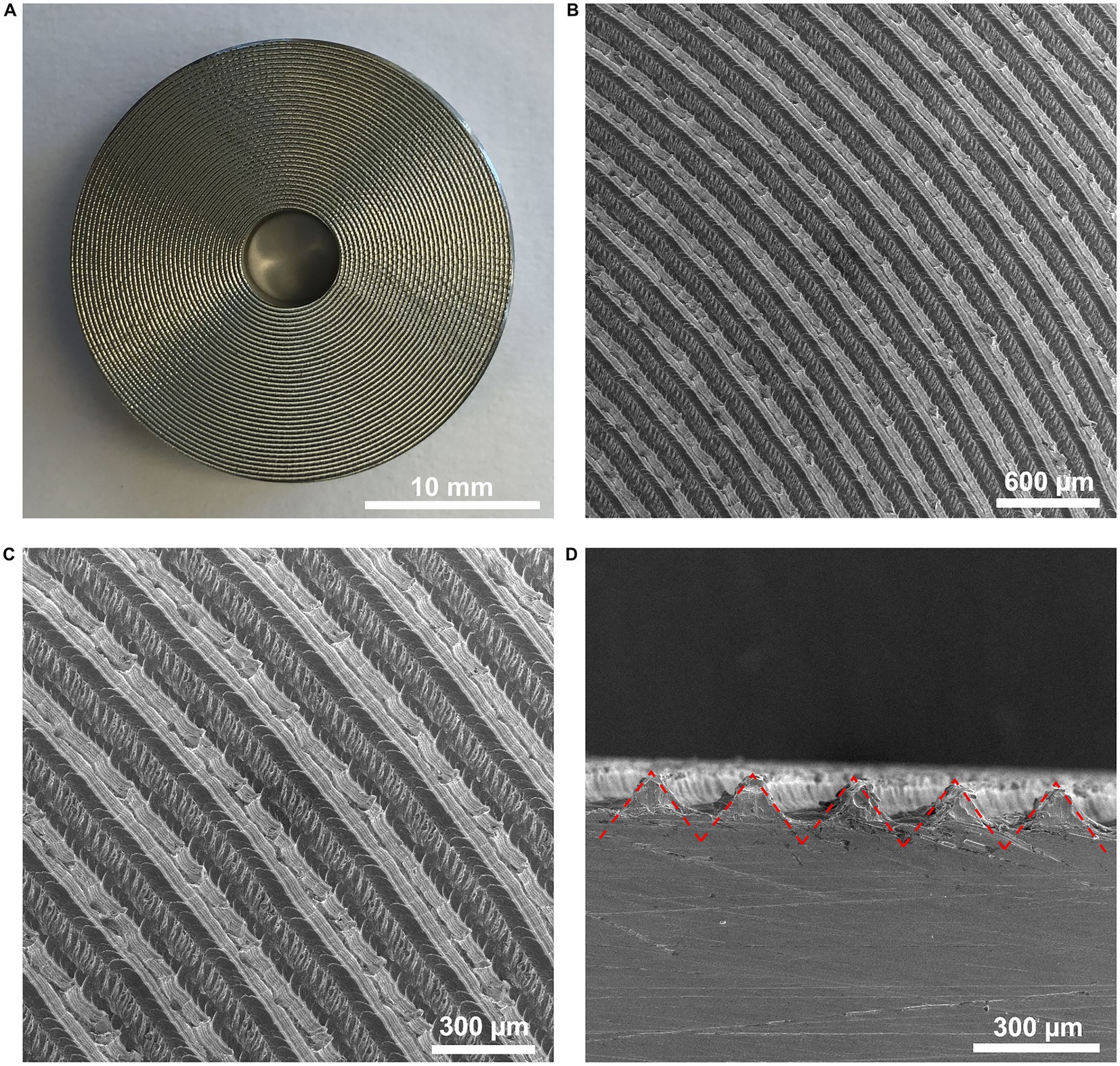
Figure 5. Ti alloy sample with engraved triangular surface structure. (A) Macroscopic top-view of the sample. One can see the triangular surface structure engraved in a spiral shape and the 5 mm borehole necessary for peel-off force measurement in the center of the sample. (B,C) Microscopic SEM top-view of the Ti alloy sample. (D) Cross section of the surface-structured Ti alloy sample with the triangular surface structure marked in red. One can see the periodic surface geometry with a tip spacing of about 250 µm and a depth of about 200 µm.
2.4. Results of the peel-off force measurements of the nonwoven layer
The peel-off force, that is, the force per unit length of the peeling edge necessary to separate the nonwoven from the surface, was measured on Ti alloy samples with triangular surface structure as well as on polished (flat) control Ti alloy samples. In Figure 6 one can see an example measurement of a polished (flat) sample (Figure 6A) and a surface-structured sample (Figure 6B). The applied weights and therefore the normal forces acting on the nonwoven layer are equal in Figures 6A,B. One can see that the cone diameter d of the peeled-off nonwoven layer is much larger for the surface-structured sample than for the polished (flat) sample, which indicates that the peel-off force is significantly lower for the surface-structured sample than for the polished (flat) sample.
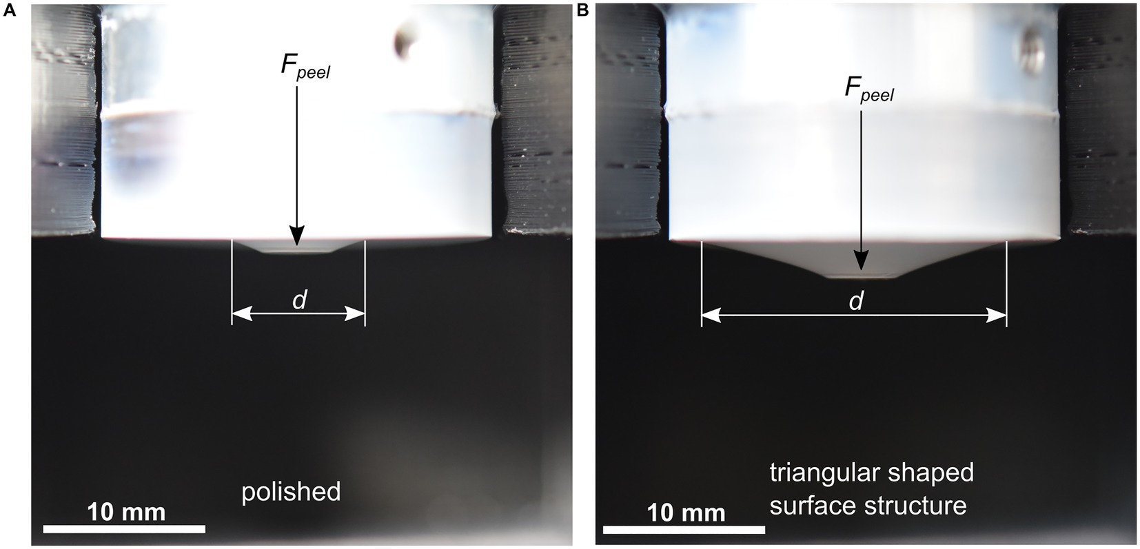
Figure 6. Peel-off force measurement of a polished (flat) control sample (A) and a triangular surface-structured Ti alloy sample (B). The applied weights and therefore also the normal forces are equal in both panels. One can see that the cone diameter d at equal applied forces is larger on the triangular surface-structured specimen than on the polished (flat) control specimen, which indicates that the peel-off force per unit length is smaller for the surface-structured sample.
In Table 1 the measured values for the peel-off force per unit length for the surface-structured and the polished (flat) samples are listed. Figure 7 shows the results presented in Table 1 graphically as bar plot. According to Table 1, the mean peel-off force for the surface-structured samples is with 0.7 N/m significantly lower than for the polished (flat) samples with 3.29 N/m. To proof the statistical significance of the measurement results, a t-test with equal variances was performed using Microsoft Excel. The two-sided t-test showed a value of p of 1.75e-11, which means that the measurement results are highly statistically significant.
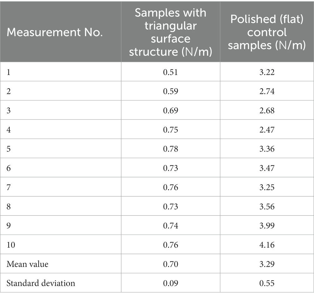
Table 1. Peel-off force per unit length measurement results.
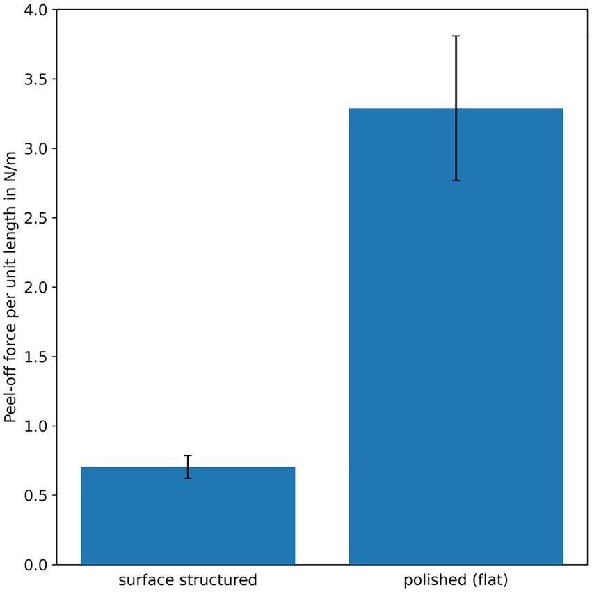
Figure 7. Results of the peel-off force per unit length measurements from Table 1 (mean values) visualized as bar plot. The error bars denote the standard deviations. The peel-off force per unit length is significant lower for the samples with the triangular surface structure, than for the polished (flat) control samples.
In Figure 8 a surface-structured sample after electrospinning is depicted. In Figure 8A one can clearly see the nonwoven nanofiber layer covering the structured sample surface. The nonwoven layer is only in contact with the tips of the triangular surface structure, which is consistent with the above presented theory. In Figure 8B one can see the same sample after peel-off force measurement, the nonwoven was completely removed from the structured surface without leaving any residues (the weight applied during peel-off force measurement for this sample was increased until the nonwoven layer broke).
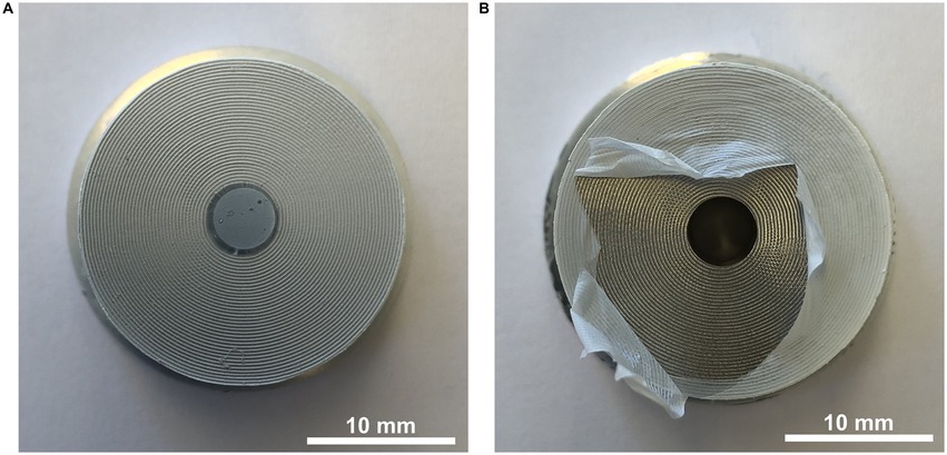
Figure 8. (A) Surface-structured sample after electrospinning covered with a nonwoven nanofiber layer. The 5 mm borehole in the center of the sample is fully covered with the nonwoven layer, which enables peel-off force measurement. (B) Surface-structured sample after peel-off force measurement. The nonwoven layer was removed without leaving any residues (the weight applied during peel-off force measurement for this sample was increased until the nonwoven layer broke).
In Figure 9 the nonwoven peeled off from the triangular surface structure is shown. In the macroscopic image Figure 9A one can see small distortions on the nonwoven where the nanofibers adhered to the tips of the triangular surface structure. In Figure 9B a SEM-image of the peeled-off nonwoven layer is depicted. Figures 9C,D show magnified sections of the area between two tips and the area where the nanofibers adhered to the tips of the triangular surface structure.
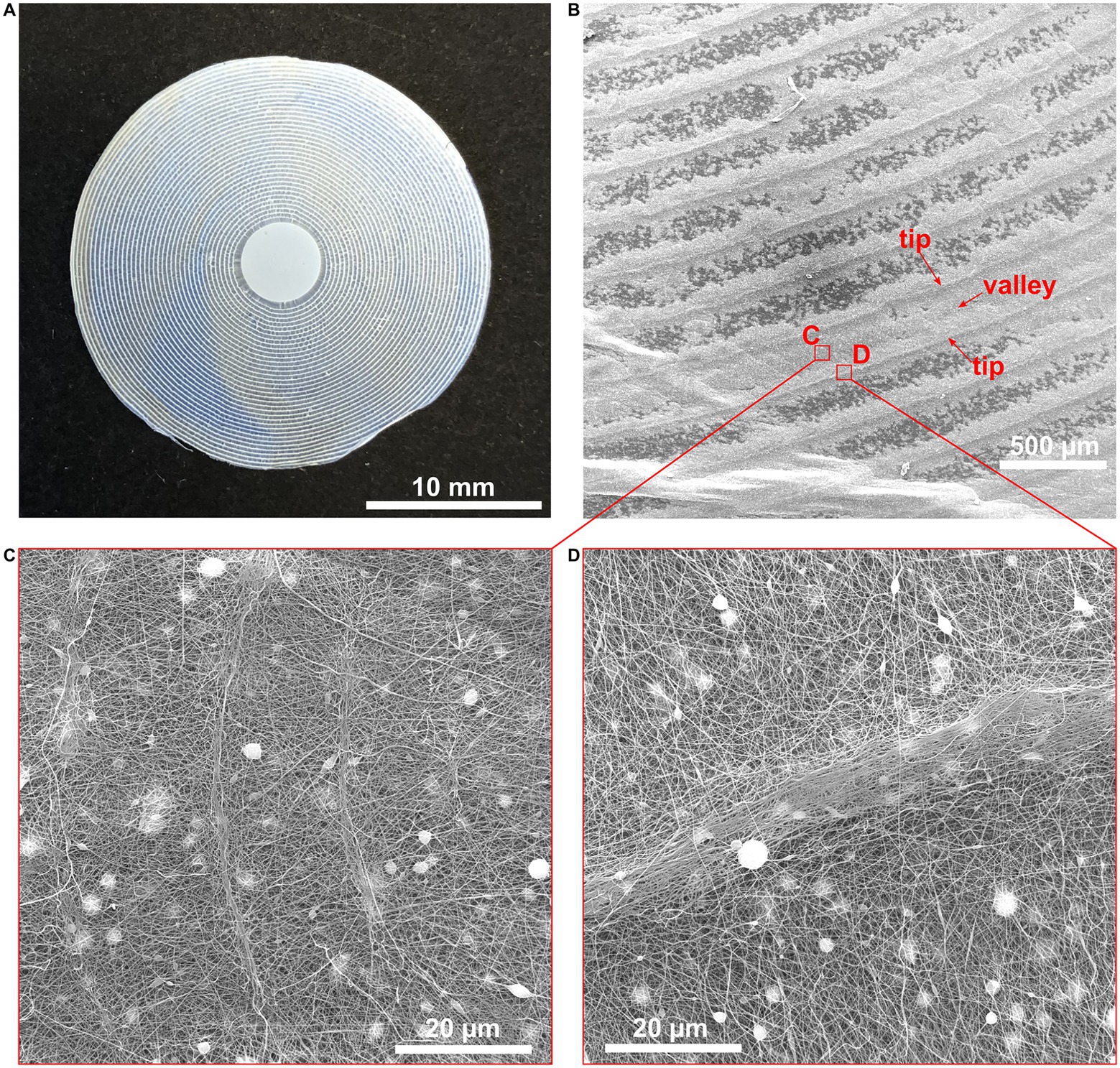
Figure 9. (A) Macroscopic image of the nonwoven layer peeled off from the triangular surface structure. One can see small distortions where the fibers adhered to the tips of the surface structure. (B) SEM-image of the nonwoven layer shown in (A). (C) Magnified view of the nonwoven layer between two tips of the triangular surface structure. (D) Magnified view of the nonwoven layer where the nanofibers adhered to the tips of the triangular surface structure. However, the nonwoven nanofiber layer looks neither faulty nor damaged in the areas where it had contact with the tips of the surface structure.
2.5. Influence of the triangular surface structure on the electric field used for electrospinning
The structured surface, especially the pointed triangular structure might influence the electric field which is used for electrospinning. To estimate the effect caused by the triangular surface structure, the electric field was calculated. The general geometry is depicted in Figure 10A. For simplicity the problem with a point source as spinning electrode is converted to a problem with an infinite plate electrode at half the distance h. In the vicinity of the center this approximation is valid and easier to handle numerically as well as analytically.
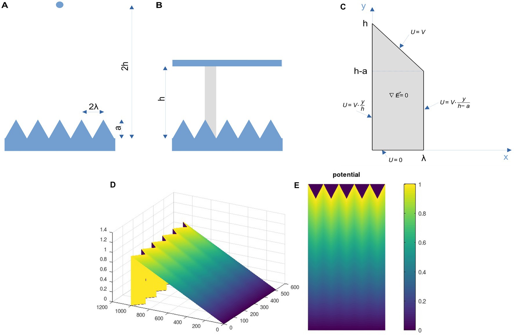
Figure 10. (A) and (B) Geometry of the field problem. The original problem (A) with a point source at the distance 2 h is converted to the approximated problem (B) with an infinite plate at the distance h. If the solution of the field problem in the gray area in (B) can be obtained, this solution can be mirrored at the vertical boarders of this area and thus the whole problem can be solved. (C) Field problem of one elementary cell. For the gray area the Laplace equation must be solved for the boundary conditions given. (D) and (E) Approximation of the potential distribution in the cleft between the triangular surface and a grounded plate. The results are shown for V = 1 and height h = 10a. The opposite polarization (grounded triangular structure and charged plate) can be explained by the linearity of the field problem in addition to a constant additional factor and a sign change.
Due to the periodic nature of the surface and the approximation using the infinite plate at distance h instead of the point at 2 h the solution of the field problem can be obtained by solving the problem for the area indicated in gray in Figure 10B. Taking this gray area and rotating it 180° for simplicity, the problem of this unit cell is shown in Figure 10C.
Due to the (mirror) symmetry of the problem, the electric field at the vertical boundary must be vertical and due to the source-free area, the divergence of the electric field must vanish everywhere. One side is grounded (potential U = 0), while the opposite electrode is at a certain potential U = V.
Now the Laplace equation has to be solved, which says for the field E and the potential U
By substituting, one can see that the following function is a solution to Laplace’s equation
This equation fulfills the Laplace equation as well as three of the four boundary conditions exactly. Only at the inclined upper part, where U = V, there is a deviation, which depends on the ratio a/h. If this ratio is small, in other words, if the distance h is larger than the amplitude of the surface structure, this approximation is pretty good as will be seen. A result for the above equation for V = 1 is shown in Figures 10D,E. The distance h was assumed to be 10 times the height a and the x-distance λ was assumed to be a/2. For this setting the boundary conditions are well fulfilled as can be seen from the 3D mesh in Figure 10D. The potential is rather homogeneous, as is the electric field. The larger the distance h compared to the amplitude a, the better the homogeneity of the field. Thus, for the typical distances in practical electrospinning, the local field distortions due to the surface structures can be neglected compared to other effects such as viscous drag or turbulent air flow. In order to verify the analytical results, we calculated the solution of the elliptic problems using the finite element method (FEM). The results are shown in Figure 11. As can be seen, the behavior of the potential distribution is in close agreement to the analytical approximation.
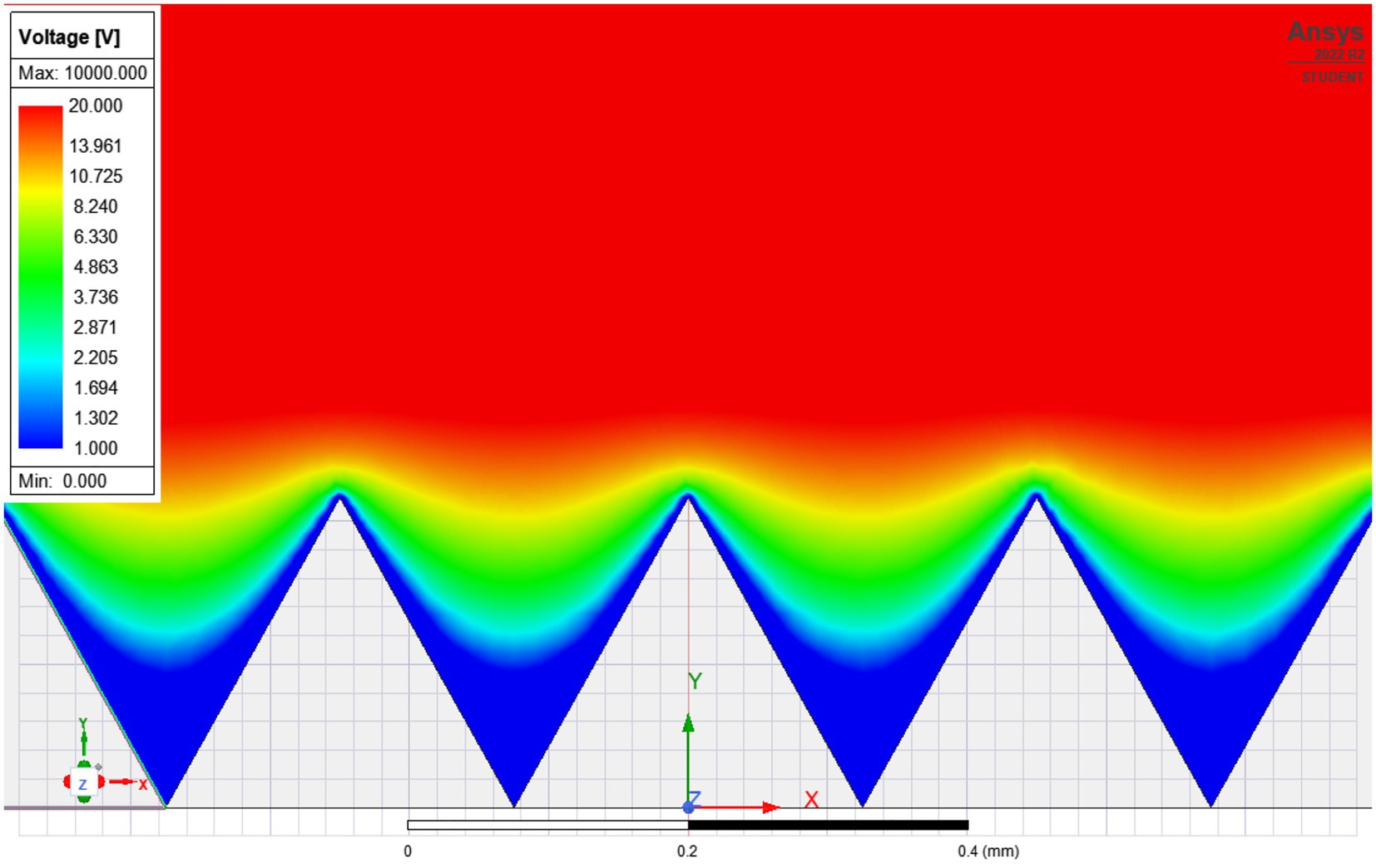
Figure 11. FEM-simulation of the electric potential over the triangular surface structure. Since the differences in the electrical potential are vanishingly small compared to the total voltage, the scale has been truncated at 20 V, since otherwise no differences in the color plot would be visible. For the typical distances in practical electrospinning, the local field distortions due to the surface structures can be neglected compared to other effects such as viscous drag or turbulent air flow.
2.6. Additional test of the triangular surface structure on a non-conductive material
In addition to the tests with the surface-structured Ti alloy samples, non-conductive surface-structured samples made of epoxy resin (identical dimensions to the Ti alloy samples) were investigated (Figures 12A,B). First measurements showed that the peel-off force for these epoxy samples is very low, as only the weight of the piston (3.1 g), which was used for the peel-off force measurement, was sufficient to completely peel off the nonwoven fabric (Figure 12C). Since this was only a first attempt, detailed measurement series are still pending to substantiate the current results.
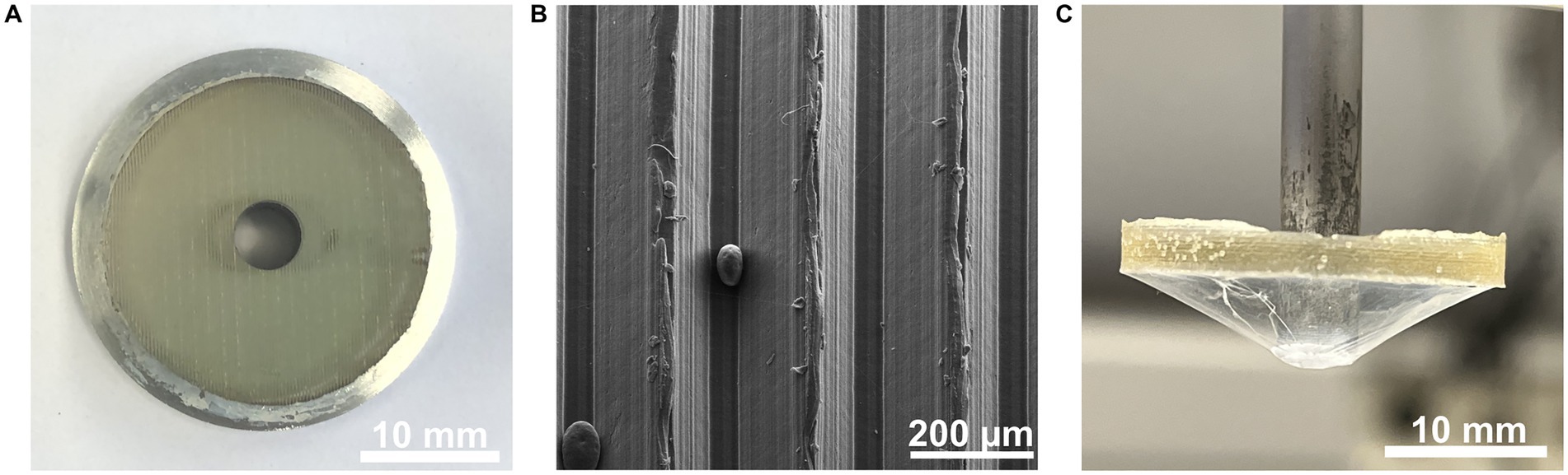
Figure 12. (A) Photography of the triangular surface-structured sample made of epoxy resin (B) SEM-image of the triangular surface structure on the epoxy resin specimen. One can see the individual triangles of the surface geometry with a tip spacing of about 250 µm. (C) Photography of the nonwoven layer peeled off from the epoxy resin sample. The weight of the piston used for peel-off force measurement was enough to detach the nonwoven layer from the surface-structured epoxy resin specimen. Note that panel (C) is depicted upside down after peel-off for reasons of better illustration.
2.7. Cylindrical surface-structured tools for nanofiber processing
Since this type of surface structure is to be used for tools or parts of tools in the production of nanofiber nonwovens, two prototypes with the triangular surface structure were fabricated. The first tool prototype, a simple surface-structured aluminum cylinder, is shown in Figure 13A. The production of the triangular surface structure on cylindrical tools is easy, as it can be simply designed as a kind of extremely fine thread. With this surface-structured cylindrical tool, it is possible, for example, to produce a continuous fiber mat of nonwoven fabric by slowly rotating the cylinder (Figure 13B). If the rotation is slow enough, the freshly spun nanofibers polymerize during rotation and can then be peeled off on the opposite side of the cylinder.
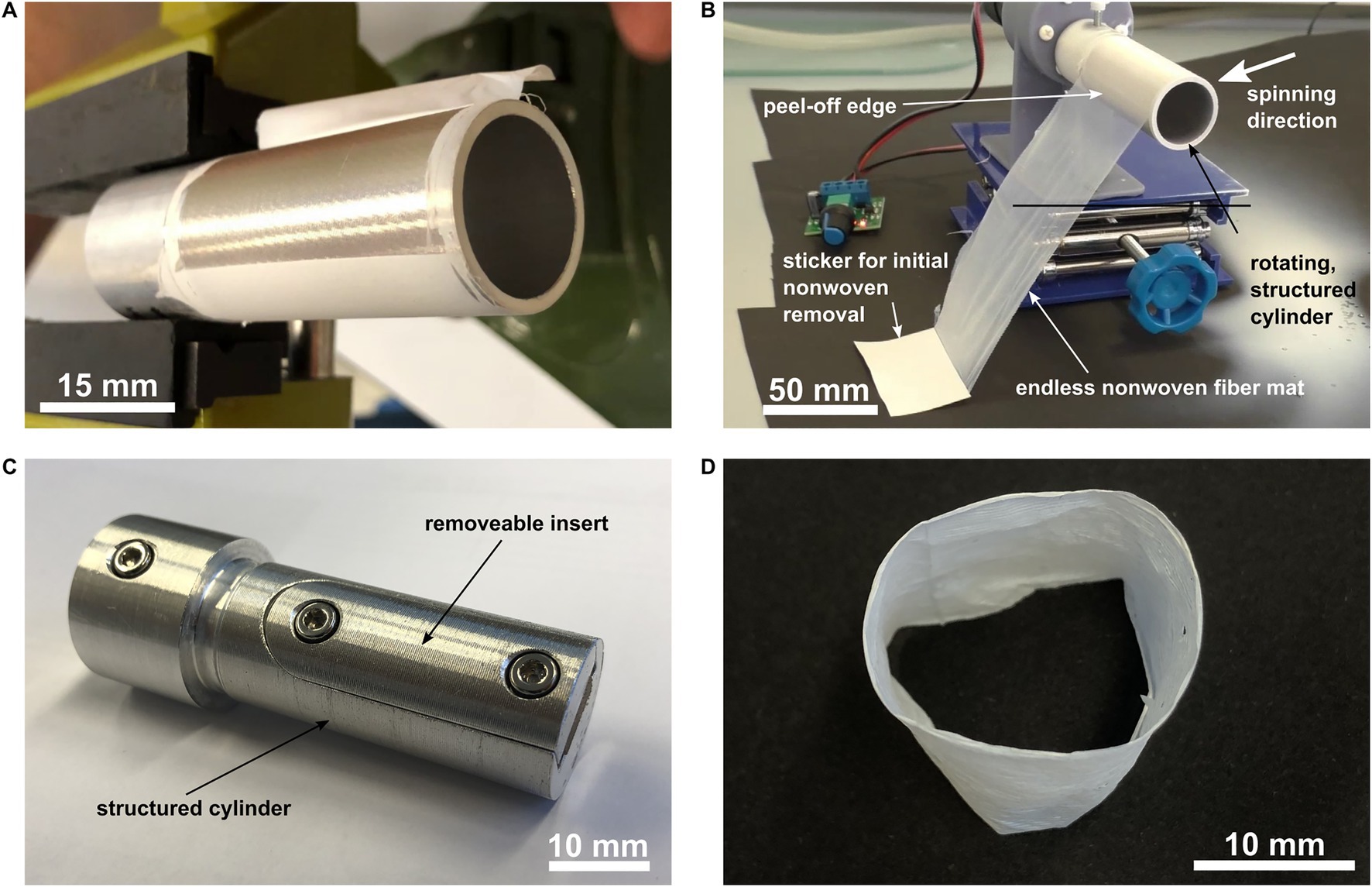
Figure 13. (A) Aluminum cylinder covered with the triangular surface structure. The nonwoven nanofiber layer can be peeled off from the cylinder easily. (B) Production of an endless nonwoven nanofiber mat. The surface-structured cylinder is slowly rotated anti clockwise. The nanofibers are electrospun from the right. During the slow rotation of the cylinder, the nonwoven layer polymerizes and can then be easily peeled off on the opposite side. By winding up the peeled off nanofiber layer, an endless nonwoven nanofiber mat can be produced. (C) Aluminum cylinder covered with triangular surface structure and additional removeable insert. The cylinder is again slowly rotated and electrospun until the whole cylinder is covered with a nanofiber layer. Subsequently, the removeable insert is removed carefully in the axial direction of the cylinder. Thereby the tension on the nonwoven layer is released and a tubular nanofiber layer can now be removed carefully in whole from the cylinder. (D) Tubular nanofiber nonwoven removed in whole from the cylindrical tool shown in (C). Video S1 in the Supplementary material explains the principle of the two tool prototypes clearly and in more detail.
Figure 13C shows a second prototype tool, which is basically also a simple aluminum cylinder. This second prototype has an additional insert that can be removed in the axial direction. When the structured surface of the cylinder is completely covered with a nonwoven nanofiber layer, the insert is carefully removed in the axial direction. As mentioned earlier, freshly spun nanofibers tend to shrink during polymerization. Removal of said insert releases the tension from the shrunk nonwoven and thus enables the removal of a tubular nonwoven (Figure 13D). Video S1 in the Supplementary material explains the principle of the two tool prototypes clearly and in more detail.
3. Discussion
In addition to the fingerprint-like surface nanostructure described in Joel et al. (2020) and Lifka et al. (2022) another structural feature can be observed on the calamistrum of cribellate spiders. The fingerprint-like surface nanostructure is located on individual, specially shaped setae (hairs). These hairs are not perfectly aligned on a plane, but arranged in an imbricated way, where the cross section of each hair can be approximated by triangle or saw-tooth shape (Figure 1). They typically measure several micrometers and are thus much larger than the fingerprint-like surface structures and typical fiber diameters.
It is difficult to separate the influence of the larger imbricated setae structure from the nanostructures using only the natural model organism. The artificial reproduction of such structures is a neat way for manipulating and testing single features, like here: leaving out the nanostructure and focusing only on the setae. Hence, one has to focus on the features, which have to be included in the abstracted model. For example, since the spiders continuously brush over the nanofibers with the calamistrum for extraction (Joel et al., 2015), we assume the nanofibers to be extracted under tension, hence a preload is necessary to integrate into the model. Indeed, the spiders were observed to exhibit behavioral adaptations to maintain this tension or proper contact between fiber and calamistrum (Joel et al., 2016). Therefore, a longitudinal force, − that is, a preload of the fibers in the natural model–can be assumed. It is also worth mentioning that not all spiders have these overlapping setae like Uloborids nor show behavioral adaptations to keep tension in the threads. Eresids, for example, do show an accumulation of the thread after production (own observations). Hence, tension within the thread during production is less likely. The calamistra setae here are single standing and do not show overlap (Miller et al., 2012).
In this work, we have presented a theoretical approach to describing the interaction between nanofibers and surface structures when a longitudinal force (i.e., fiber preload) occurs, which can become a dominant effect for large surface structures (large compared to the fiber diameter). For reasons of symmetry, we used a triangular rather than a saw-tooth shape for modelling, which made the necessary calculations easier. Furthermore, a triangular shape is much easier to manufacture in terms of production technology. A saw-tooth shape could be the subject of future research.
The theoretical model presented can now be used to predict an optimal surface structure for tools anti-adhesive to electrospun nanofibers. The requirements of the surface structure can be summarized as follows:
(i) The surface structure is periodical and as sharply tipped as possible.
(ii) The ideal slope for the periodic surface structure can be determined from Equation 11 and Figure 4, given the following fiber material properties: elastic modulus, shrinkage and Hamaker constant.
(iii) The ideal spacing of the periodic structures is as large as possible, but smaller than the characteristic length of the nanofibers, which is determined by the higher order bending instabilities. Currently, this characteristic length must be determined experimentally.
In order to verify the models presented, surface-structured specimens were produced from a Ti alloy in accordance with the theory. The triangular surface structure with an angle of 30° and a peak spacing of 250 μm was fabricated using CNC milling and engraving. The surface-structured and polished (flat) control samples were electrospun to create a nonwoven nanofiber layer on the surfaces under investigation. Although the electrospinning process forms a nonwoven mesh of randomly oriented nanofibers, the first contact of the fiber with the surface structure takes place in the form of a single fiber, which means that the presented theory is still valid. The peel-off forces (i.e., the force required to detach the nonwoven layer from the sample surface) were measured for the surface-structured and the control specimens. The measurement results showed that–compared to a polished, completely flat surface–the triangular surface structure reduced the peel-off force by approximately 80%.
Note that the tip spacing and depth are much larger than in the natural model. This is partly due to the limited fabrication capabilities, as we are not able to produce such small surface structures using CNC engraving, and partly because the fiber diameters in the natural model being much smaller than the diameters achieved with our electrospinning setup. The fiber diameters of the cribellar fibrils from the natural model range from 10 nm to 30 nm (Joel et al., 2020), while the diameters of the artificial electrospun nanofibers are typically >100 nm, thus much larger. Further, the elastic modulus and the tensile strength are different between natural spider silk and electrospun PA6 nanofibers (Opell and Bond, 2001; Bazbouz and Stylios, 2010). In principle, it is difficult to compare the mechanical properties of the two fibers exactly, since the cribellar capture threads under investigation have a special structure of axial support fibers surrounded by cribellar fibrils in the form of individual puffs, while electrospun nanofibers consist of only a single fiber. However, both fiber types show initial linear elastic behavior (Bazbouz and Stylios, 2010; Piorkowski and Blackledge, 2017) and the presented anti-adhesive surface structure seems to work also for artificial electrospun nanofibers.
Adhesion forces of cribellate fibers to any (non-waxy) surface, also unstructured ones, are already very low. See for example Hawthorn and Opell (2003) measuring a stickiness between 40 μN and 80 μN, with similar values measured in our lab (Bott et al., 2017). As soon as surfaces are predicted to be antiadhesive towards nanofibers, forces are even lower. Thus, unfortunately, we cannot use the setup presented in this work to measure the forces of the cribellate threads on any anti-adhesive surface.
In addition, again due to limited manufacturing capabilities, we could not produce a perfectly triangular surface structure as assumed in the theoretical model. Since titanium alloys are generally difficult to machine tip angle, tip spacing and depth did not perfectly match those of the underlying model. Furthermore, a fine burr can sometimes be observed at the tips of the triangular surface structure due to the engraving process, which leads to a deviation from the ideal, “infinitely sharp” triangular shape. Despite all these deviations from a perfect triangular shape, a significantly lower peel-off force was observed for the surface-structured Ti alloy specimens than for the polished (flat) control specimens.
Quantification of the exact shrinkage of the electrospun nanofibers is unfeasible, but this parameter is important for the optimal selection of angle α. In particular, during the production of the tubular nonwoven shown in Figure 13D, we observed a rather high shrinkage of the fibers when the nonwoven was removed. Therefore, a high shrinkage value was assumed in the theoretical model.
In Figure 9, small distortions on the nonwoven that peeled off the triangular surface structure can be observed. The areas where the nanofibers adhered to the tips of the structure are visible in the macroscopic and microscopic images. However, the nonwoven nanofiber layer looks neither faulty nor damaged in the areas where it had contact with the tips of the surface structure. Further investigations of the influence of the triangular surface structure on the quality of the nonwoven may be necessary.
The natural model features a combination of the larger surface microstructure presented here and the fingerprint-like nanostructure. As the sample material for the triangular surface structure was chosen to be a Ti alloy, a combination of the large triangular surface structure with the fingerprint-like structure produced using laser-induced periodic surface structures (LIPSS) (Bonse and Krüger, 2012), as presented in Lifka et al. (2022), is the subject of future research. As hardened steel is extremely difficult or even impossible to machine or engrave, and the quality of the LIPSS produced on aluminum alloy is not sufficiently high to achieve anti-adhesiveness (Lifka et al., 2022), titanium alloy is the best and logical choice. A combination of these two surface structures in engineered surfaces, resulting in a hierarchical surface structure as in the natural model, may make nanofiber adhesion even lower than for the two separate surface structures. Such a combined model could give again valuable information about the interplay between both structures on the spider’s calamistrum.
The prototypes for the cylindrical surface-structured tools were made from aluminum because it is much cheaper and much easier to handle in the course of manufacturing than a titanium alloy, and thus more suitable for a first proof of concept. Future tool prototypes could be made from a titanium alloy so that the fingerprint-like and triangular surface structures can be combined in tools for nanofiber handling.
Only one type of fiber and one set of surface-structure dimensions were investigated in this work. In principle this surface structure can be adapted to suit the requirements of various types of fibers (e.g., with different diameters and bending stiffnesses) within technical limits by simply adjusting tip spacing, tip height, and slope.
Showing already the influence of macrostructure onto nanofibers under preload should make us consider the larger morphological features of the calamistrum as well, focusing not only on the surface nanostructure. Therefore, in future work it would be interesting to study the larger microstructures in more detail with respect to their exact geometry and dimensions. Furthermore, an exact measurement of the fiber preload during the spinning process would be interesting to substantiate the assumptions made here. Also, a detailed comparison of the spinning mechanics with respect to fiber preload between spiders where the individual setae show this triangular overlap and spiders where the single setae do not show any overlap would be of great interest.
Such surface structures may be beneficial for tools or parts of tools used in nanofiber production, handling, and processing. As adhesion of the nonwoven nanofiber layer is significantly lower with this surface structure, the risk of damaging the nonwoven or of leaving residues is reduced and could therefore make production, handling, and processing much easier in the future.
4. Materials and methods
4.1. Sample materials
The titanium alloy (grade-5 titanium alloy: Ti6Al4V) for the samples was purchased from Schumacher Titan GmbH (Solingen, Germany) as rods of 25 mm diameter. The rods were reduced to 24 mm diameter and cut into approximately 8 mm thick slabs. The top surfaces of the samples were mechanically polished resulting in a surface with an average roughness of Ra < 15 nm. In order to allow a peel-off force measurement, a 5 mm borehole was drilled through the center of the sample (Lifka et al., 2022).
4.2. Focused-ion beam (FIB) cuts
The calamistra of Uloborus plumipes were prepared by detaching the fourth legs proximally to the metatarsus. Samples were subsequently allowed to air dry and placed on SEM stubs equipped with carbon adhesive tape. A stereomicroscope was used to ensure that the metatarsus was oriented so that the calamistrum pointed vertically upward. Threads of Uloborus plumipes were retrieved from the spider’s web using tweezers and placed perpendicular to the metatarsus over the calamistrum. Care was taken to stretch the thread as little as possible. Afterwards, samples were sputter-coated with a ± 10 nm gold layer (Sputter coater S150B, Edwards Ltd., Burgess, United Kingdom) before FIB-milling and SEM imaging (Strata 400 STEM, FEI Company, Oregon, United States).
4.3. Manufacturing of the surface structures
The triangular surface structure was manufactured by means of CNC-milling on a portal milling machine PRO-BASIC-H 06/05 (CNC-Modellbau, Gerabronn, Germany) with a 3S Step-control (CNC-Modellbau, Gerabronn, Germany) and a Kress 800 FME milling spindle (KRESS-elektrik GmbH & Co. KG, Bisingen, Germany), which was controlled via the software WinPC-NC USB (Burkhard Lewetz Hard–und Software, Meckenbeuren, Germany; Version: 2.50/20). Before the triangular surface was manufactured the sample was face milled with a 1.5 mm finishing cutter (Paulitschek Maschinen–und Warenvertriebsgesellschaft mbH, Neu-Ulm, Germany; Item number: 13631) to achieve a plane and parallel surface. The face milling process was carried out in three passes. The infeed depth of the first two passes was set to 200 μm, the infeed depth of the last pass was set to 100 μm, giving a maximum depth of 500 μm. The cutting speed and the feed per tooth for face milling were set to 47 m/min and 0.025 mm, respectively.
Subsequently, the triangular surface structure was engraved using a spiralized engraving cutter with a (full) tip angle of 60° (Item number: KM-GSS, CNC-Technik Haase GmbH, Neuss, Germany). The triangular structure was engraved spirally into the round sample with a spacing of 250 μm and a maximum depth of 200 μm. A spiral shape was used to ensure continuous engagement of the engraving cutter in the material during the entire production time. The maximum infeed depth of one pass of the engraving process was set at 50 μm. To achieve a maximum depth of 200 μm, four passes were required. Due to the 60° tip angle of the engraving cutter, a triangular structure with α = 30° is automatically achieved. The spindle speed and the feed per tooth for engraving were set to 29,000 min−1 (maximum spindle speed of the CNC-machine used) and 0.015 mm, respectively.
The CAD/CAM-data was created with Autodesk Fusion 360 (Autodesk, Inc., San Rafael, CA, United States). Both, face milling and engraving of the triangular surface structure were carried out under sufficient cooling with cooling lubricant. To get rid of the small titanium chips stuck between the triangular surface structures the samples were washed in an ultra-sonic bath (SONOREX SUPER RK 31, BANDELIN electronic GmbH & Co. KG, Berlin, Germany) for a few minutes, treated with a laboratory brush, and finally cleaned with 80% ethanol.
4.4. Electrospinning process
The electrospinning process was performed using a custom-made setup like shown in Supplementary Figure S2 (Supplementary material). The setup consists of a custom-made syringe pump, a 1 ml plastic syringe (Omnifix-F, B. Braun SE, Melsungen, Germany), a blunt needle tip (Sterican 21G x 7/8″ blunt, B. Braun SE, Melsungen, Germany), and a high-voltage generator (HCP 35–35,000, FuG Elektronik GmbH, Schechen, Germany). The sample was fixed on a sample carrier made of aluminum with double-sided adhesive tape, which is necessary for the later peel-off force measurement. The sample and the sample carrier were then fixed on an aluminum piston having a diameter of 5 mm, which was connected to the ground electrode of the high-voltage generator. The custom-made syringe pump was placed horizontally (to avoid droplets falling onto the sample and destroying the nonwoven) opposite to the sample at a needle to sample surface distance of about 13 cm. The positive electrode of the high-voltage generator was directly clamped onto the blunt needle tip by means of an alligator clamp. The height of both, the sample and the syringe pump, was adjusted by a lab boy.
As dope solution a liquid polyamide 6 solution consisting of 6 g PA6 granulate, 15 g formic acid, and 29 g acetic acid was used. The solution was prepared by mixing at 80°C for about 90 min. For electrospinning the solution was delivered through the syringe and the blunt needle tip by the custom-made syringe pump at a flow rate of approximately 15 ml/s. The voltage between the positive and the ground electrode of the high-voltage generator was set to 19 kV. The spinning process duration for each sample was approximately 7 min, which was enough to achieve a sufficient thick nonwoven layer covering the whole sample surface. The ambient temperature and humidity during electrospinning were approximately 21°C and 30%, respectively.
4.5. Peel-off force measurement
The peel-off force measurement was performed using a newly established peel-off test as already described in detail in a previous work (Lifka et al., 2022). The sample fixed on the aluminum sample carrier was placed upside down in a custom-made 3D-printed mount. The whole setup was then placed onto a precision scale (KERN PLS 4200-2F, KERN & SOHN GmbH, Balingen-Frommen, Germany) and tared to zero. The aluminum piston pushing the nonwoven from the sample surface was put through the borehole in the center of the sample. Different weights were then successively applied onto the aluminum piston, the weight was read from the display of the precision scale and an image of the resulting nonwoven-cone was taken with an SLR camera (Nikon D5300, Nikon Corporation, Tokyo, Japan) equipped with a macro lens (AF-S Micro–NIKKOR 60 mm 1:2,8 ED, Nikon Corporation, Tokyo, Japan). The respective cone diameter was measured using the freeware Inkscape (V. 1.2.1, Inkscape Community) and the peel-off force was calculated according to Lifka et al. (2022) using Microsoft Excel (V 16.62, Microsoft, Washington, United States). Prior to the measurements the samples were cleaned with 80% ethanol.
4.6. FEM-simulation of the electric field distribution on the triangular surface structure
The FEM-simulation of the electric field distribution was done with the software Ansys Maxwell (Version: 2022 R2 Student, Ansys, Inc., Canonsburg, PA, United States). The positive electrode was approximated by a horizontal plate like assumed in the calculations above. The triangular surface structure was modelled using separate triangles with the respective dimensions (tip spacing 250 μm and tip height 200 μm). The potential of the needle was set to 10 kV and the potential of the triangular surface structure was set to zero (i.e., ground). The distance between needle and structure was chosen to be 5 cm. The materials for the electrodes were chosen to be copper for the positive electrode and titanium for the triangular structure (i.e., the ground electrode).
4.7. Manufacturing of the triangular surface structures on the cylindrical prototype tools and on epoxy resin
The manufacturing of the triangular surface structure on a cylindrical aluminum tool was done as follows. The aluminum cylinder was clamped into a turning lathe (PD 400, PROXXON S.A., Wecker, Germany) and longitudinal turned to achieve a smooth surface. The surface structure was then produced using a metric 60° thread turning tool and the automatic feed of the turning lathe. In principle the triangular surface structure on a cylindrical tool can be considered as a very fine thread. The “thread pitch” (i.e., the tip spacing) was set to 250 μm and therefore identical to the tip spacing used with the milled Ti alloy samples. The surface structure was manufactured in several passes with an infeed of approximately 50 μm per pass and a total depth of the surface structure of approximately 200 μm. The lowest possible speed of the lathe (i.e., 80 min−1) was set.
For production of the triangular surface structure in epoxy resin the surface-structured aluminum cylinder tool was used as template. By applying A-silicone impression material (PRESIDENT Xtra light body, Colténe/Whaledent AG, Altstätten, Swiss) on the surface of the cylindrical tool, a negative of the surface structure was created. The negative made of A-silicone was then used as a mold for production of the surface-structured epoxy resin sample. This results in a triangular surface structure on the epoxy resin sample aligned in straight lines instead of a spiral like on the Ti alloy samples. The epoxy sample has a diameter of about 25 mm and a 5 mm borehole was drilled into the sample center for peel-off force measurement.
5. Conclusion
Nanofibers (e.g., produced by means of electrospinning) draw more and more attention to scientists and engineers due to their enormous surface-to-volume ratio which is advantageous in a broad field of application. However, very little attention has been paid to a key issue in the production of nanofibers, namely the adhesion of the fibers to the surface of an object during production, especially during electrospinning. By taking a look into nature, animals which are able to produce, handle, and process nanofibers can be found, namely cribellate spiders. Inspired by a structural feature of the calamistrum of Uloborus plumipes, we derived a theoretical model of the adhesion between thin nanofibers and surfaces structures with dimensions large compared to the nanofiber diameter in presence of a longitudinal force acting on the fiber (i.e., fiber preload). The theory was verified experimentally with artificial electrospun nanofibers and surface-structured samples made of titanium alloy. Measurements of the peel-off forces (i.e., the force required to detach the nonwoven layer from the sample surface) showed a significant reduction in adhesion on an appropriately structured surface compared to a flat, unstructured surface. Therefore, such a surface structure can be used for tools or parts of tools during nanofiber production (e.g., as part of the electrospinning process) to reduce the adhesion of the nonwoven fabric and thus facilitate the handling and processing of the nanofibers during production.
Data availability statement
The original contributions presented in the study are included in the article/Supplementary material, further inquiries can be directed to the corresponding author.
Ethics statement
Ethical review and approval was not required for the animal study because the species used in the experiments is not an endangered or protected species. All applicable international, national, and institutional guidelines for the care and use of animals were followed.
Author contributions
WB performed the theoretical modelling. SL performed the experiments, analyzed, and interpreted the data. CS calculated and simulated the electric field distributions. MM and A-CJ investigated the natural model. SL and WB drafted the initial manuscript. MM and A-CJ critical reviewed the initial draft. JH had management and coordination responsibility for the planning and execution of the research activities, was responsible for acquiring financial support for the project leading to this publication and critical reviewed the revised draft. All authors contributed to the article and approved the submitted version.
Funding
This work was supported by the European Union’s Horizon 2020 research and innovation program within the project “BioCombs4Nanofibers” (Grant Agreement No. 862016, http://biocombs4nanofibers.eu). Open access funding provided by Johannes Kepler University Linz and the Linz Center of Mechatronics (LCM).
Acknowledgments
We would like to thank the ZONA for polishing the surface of the Ti alloy samples.
Conflict of interest
The authors declare that the research was conducted in the absence of any commercial or financial relationships that could be construed as a potential conflict of interest.
Publisher’s note
All claims expressed in this article are solely those of the authors and do not necessarily represent those of their affiliated organizations, or those of the publisher, the editors and the reviewers. Any product that may be evaluated in this article, or claim that may be made by its manufacturer, is not guaranteed or endorsed by the publisher.
Supplementary material
The Supplementary material for this article can be found online at:
https://www.frontiersin.org/articles/10.3389/fevo.2023.1099355/full#supplementary-material
References
Akampumuza, O., Gao, H., Zhang, H., Wu, D., and Qin, X.-H. (2017). Raising nanofiber output: the progress, mechanisms, challenges, and reasons for the pursuit. Macromol. Mater. Eng. 303:1700269. doi: 10.1002/mame.201700269
Avossa, J., Batt, T., Pelet, T., Sidjanski, S. P., Schönenberger, K., and Rossi, R. M. (2021). Polyamide nanofiber-based air filters for transparent face masks. ACS Appl. Nano Mater. 4, 12401–12406. doi: 10.1021/acsanm.1c02843
Barthlott, W., and Neinhuis, C. (1997). Purity of the sacred lotus, or escape from contamination in biological surfaces. Planta 202, 1–8. doi: 10.1007/s004250050096
Bazbouz, M. B., and Stylios, G. K. (2010). The tensile properties of electrospun nylon 6 single nanofibers. J. Polym. Sci. B Polym. Phys. 48, 1719–1731. doi: 10.1002/polb.21993
Bonse, J., and Krüger, J. (2012). Femtosecond laser-induced periodic surface structures. J. Laser Appl. 24:042006. doi: 10.2351/1.4712658
Bott, R. A., Baumgartner, W., Bräunig, P., Menzel, F., and Joel, A.-C. (2017). Adhesion enhancement of cribellate capture threads by epicuticular waxes of the insect prey sheds new light on spider web evolution. Proc. R. Soc. B 284:20170363. doi: 10.1098/rspb.2017.0363
Du, Y., Zhang, X., Liu, P., Yu, D.-G., and Ge, R. (2022). Electrospun nanofiber-based glucose sensors for glucose detection. Front. Chem. 10:944428. doi: 10.3389/fchem.2022.944428
Duleba, B., Spišák, E., and Greškovič, F. (2014). Mechanical properties of PA6/MMT polymer nanocomposites and prediction based on content of nanofiller. Proc. Eng. 96, 75–80. doi: 10.1016/j.proeng.2014.12.100
Eichenlaub, S., Chan, C., and Beaudoin, S. P. (2002). Hamaker constants in integrated circuit metalization. J. Colloid Interface Sci. 248, 389–397. doi: 10.1006/jcis.2002.8241
Gorji, M., Jeddi, A. A. A., and Gharehaghaji, A. A. (2012). Fabrication and characterization of polyurethane electrospun nanofiber membranes for protective clothing applications. J. Appl. Polym. Sci. 125, 4135–4141. doi: 10.1002/app.36611
Hameed, A., Rehman, T. U., Rehan, Z. A., Noreen, R., Iqbal, S., Batool, S., et al. (2022). Development of polymeric nanofibers blended with extract of neem (Azadirachta indica), for potential biomedical applications. Front. Mater. 9:1042304. doi: 10.3389/fmats.2022.1042304
Hawthorn, A. C., and Opell, B. D. (2003). Van der Waals and hygroscopic forces of adhesion generated by spider capture threads. J. Exp. Biol. 206, 3905–3911. doi: 10.1242/jeb.00618
Jiang, W., Zhang, X., Liu, P., Zhang, Y., Song, W., Yu, D.-G., et al. (2022). Electrospun healthcare nanofibers from medicinal liquor of Phellinus igniarius. Adv. Compos. Hybrid Mater. 5, 3045–3056. doi: 10.1007/s42114-022-00551-x
Joel, A.-C., Kappel, P., Adamova, H., Baumgartner, W., and Scholz, I. (2015). Cribellate thread production in spiders: complex processing of nano-fibres into a functional capture thread. Arthropod Struct. Dev. 44, 568–573. doi: 10.1016/j.asd.2015.07.003
Joel, A.-C., Meyer, M., Heitz, J., Heiss, A., Park, D., Adamvoa, H., et al. (2020). Biomimetic combs as antiadhesive tools to manipulate nanofibers. ACS Appl. Nano Mater. 3, 3395–3401. doi: 10.1021/acsanm.0c00130
Joel, A.-C., Scholz, I., Orth, L., Kappel, P., and Baumgartner, W. (2016). Morphological adaptation of the calamistrum to the cribellate spinning process in Deinopoidae (Uloboridae, Deinopidae). R. Soc. Open Sci. 3:150617. doi: 10.1098/rsos.150617
Koch, K., Bohn, H. F., and Barthlott, W. (2009). Hierarchically sculptured plant surfaces and superhydrophobicity. Langmuir 25, 14116–14120. doi: 10.1021/la9017322
Lifka, S., Harsányi, K., Baumgartner, E., Pichler, L., Baiko, D., Wasmuth, K., et al. (2022). Laser-processed antiadhesive bionic combs for handling of nanofibers inspired by nanostructures on the legs of cribellate spiders. Beilstein J. Nanotechnol. 13, 1268–1283. doi: 10.3762/bjnano.13.105
Liu, Y., Chen, X., Gao, Y., Yu, D.-G., and Liu, P. (2022). Elaborate design of shell component for manipulating the sustained release behavior from core-shell nanofibers. J. Nanobiotechnol. 20:244. doi: 10.1186/s12951-022-01463-0
Liu, H., Wang, H., Lu, X., Murugadoss, V., Huang, M., Yang, H., et al. (2022). Electrospun structural nanohybrids combining three composites for fast helicide delivery. Adv. Compos. Hybrid Mater. 5, 1017–1029. doi: 10.1007/s42114-022-00478-3
Miller, J., Griswold, C., Scharff, N., Rezac, M., Szuts, T., and Marhabaie, M. (2012). The velvet spiders: an atlas of the Eresidae (Arachnida, Araneae). ZooKeys. 195, 1–144. doi: 10.3897/zookeys.195.2342
Opell, B. D., and Bond, J. E. (2001). Changes in the mechanical properties of capture threads and the evolution of modern orb-weaving spiders. Evol. Ecol. Res. 3, 567–581.
Parsegian, V. (2005). Van der Waals Forces: A Handbook for Biologists, Chemists, Engineers, and Physicists. Cambridge: Cambridge University Press.
Piorkowski, D., and Blackledge, T. A. (2017). Punctuated evolution of viscid silk in spider orb webs supported by mechanical behavior of wet cribellate silk. Sci. Nat. 104:67. doi: 10.1007/s00114-017-1489-x
Ramakrishna, S., Fujihara, K., Teo, W.-E., Yong, T., Ma, Z., and Ramaseshan, R. (2006). Electrospun nanofibers: solving global issues. Mater. Today 9, 40–50. doi: 10.1016/S1369-7021(06)71389-X
Reneker, D. H., and Fong, H. (2005). Polymeric Nanofibers. Washington, DC: American Chemical Society.
SalehHudin, H. S., Mohamad, E. N., Mahadi, W. N. L., and Afifi, A. M. (2018). Multiple-jet electrospinning methods for nanofiber processing: a review. Mater. Manuf. Process. 33, 479–498. doi: 10.1080/10426914.2017.1388523
Wang, X., Drew, C., Lee, S.-H., Senecal, K. J., Kumar, J., and Samuelson, L. A. (2002). Electrospun nanofibrous membranes for highly sensitive optical sensors. Nano Lett. 2, 1273–1275. doi: 10.1021/nl020216u
Wu, Y., Wang, L., Guo, B., and Ma, P. X. (2017). Interwoven aligned conductive nanofiber yarn/hydrogel composite scaffolds for engineered 3D cardiac anisotropy. ACS Nano 11, 5646–5659. doi: 10.1021/acsnano.7b01062
Xu, H., Zhang, F., Wang, M., Lv, H., Yu, D.-G., Liu, X., et al. (2022). Electrospun hierarchical structural films for effective wound healing. Biomater. Adv. 136:212795. doi: 10.1016/j.bioadv.2022.212795
Yuan, C. (2021). The shrinking behavior, mechanism and anti-shrinkage resolution of an electrospun PLGA membrane. J. Mater. Chem. B 9, 5861–5868. doi: 10.1039/D1TB00734C
Yusoff, Y. N., and Shaari, N. (2021). An overview on the development of nanofiber-based as polymer electrolyte membrane and electrocatalyst in fuel cell application. Int. J. Energy Res. 45, 18441–18472. doi: 10.1002/er.7020
Zhang, B., Kang, F., Tarascon, J.-M., and Kim, J.-K. (2016). Recent advances in electrospun carbon nanofibers and their application in electrochemical energy storage. Prog. Mater. Sci. 76, 319–380. doi: 10.1016/j.pmatsci.2015.08.002
Keywords: biomimetics, electrospinning, nanofibers, antiadhesive, surface structures, cribellate spider, calamistrum, Van der Waals force
Citation: Lifka S, Stecher C, Meyer M, Joel A-C, Heitz J and Baumgartner W (2023) Biomimetic, antiadhesive surface structure inspired by the calamistra setae of cribellate spiders for electrospun nanofiber handling. Front. Ecol. Evol. 11:1099355. doi: 10.3389/fevo.2023.1099355
Edited by:
Sang-im Lee, Daegu Gyeongbuk Institute of Science and Technology (DGIST), Republic of KoreaReviewed by:
Varsha Khare, Seoul National University, Republic of KoreaDeng-Guang Yu, University of Shanghai for Science and Technology, China
Copyright © 2023 Lifka, Stecher, Meyer, Joel, Heitz and Baumgartner. This is an open-access article distributed under the terms of the Creative Commons Attribution License (CC BY). The use, distribution or reproduction in other forums is permitted, provided the original author(s) and the copyright owner(s) are credited and that the original publication in this journal is cited, in accordance with accepted academic practice. No use, distribution or reproduction is permitted which does not comply with these terms.
*Correspondence: Sebastian Lifka, sebastian.lifka@jku.at