Frequency-Diverse Holographic Metasurface Antenna for Near-Field Microwave Computational Imaging
 Jiaqi Han1,2
  Long Li1,2* Shuncheng Tian1 Xiangjin Ma1 Qiang Feng1,2 Haixia Liu1,2 Yu Zhao1,2 Guisheng Liao3
- 1Key Laboratory of High Speed Circuit Design and EMC of Ministry of Education, School of Electronic Engineering, Xidian University, Xi’an, China
- 2Center of Intelligent Metamaterials, Pazhou Laboratory, Guangzhou, China
- 3National Laboratory of Radar Signal Processing, Xidian University, Xi’an, China
This article presents a holographic metasurface antenna with stochastically distributed surface impedance, which produces randomly frequency-diverse radiation patterns. Low mutual coherence electric field patterns generated by the holographic metasurface antenna can cover the K-band from 18 to 26 GHz with 0.1 GHz intervals. By utilizing the frequency-diverse holographic metasurface (FDHM) antenna, we build a near-field microwave computational imaging system based on reflected signals in the frequency domain. A standard horn antenna is adopted to acquire frequency domain signals radiated from the proposed FDHM antenna. A detail imaging restoration process is presented, and the desired targets are correctly reconstructed using the 81 frequency-diverse patterns through full-wave simulation studies. Compressed sensing technique and iterative shrinkage/thresholding algorithms are applied for the imaging reconstruction. The achieved compressive ratio of this computational imaging system on the physical layer is 30:1.
Introduction
Computational imaging (CI) on the physical layer based on metamaterials is an emerging research hotspot for both metamaterial applications and microwave imaging (Hunt et al., 2013). Compared with traditional microwave imaging techniques, for example, range migration, microwave holography, or synthetic aperture radar (Lopez–Sahcnez and Fortuny–Guasch, 2000; Sheen et al., 2001; Moreira et al., 2013), metamaterial apertures leveraging compressed sensing (CS) for CI possess simple structure, light weight, and low cost. Since major imaging restoration resources are recovery systems using CS theory, we could remarkably reduce the complexity and cost of imaging hardware systems (Duarte et al., 2008). The term CI is considered to describe data acquisition on the hardware layer and data post-process (imaging reconstruction) on the CS algorithm layer.
The first metamaterial aperture for CI was reported in the study by Hunt et al. (2013). By utilizing frequency-diverse leaky-wave metamaterial unit cells, randomly distributed radiation patterns, satisfying compressed sampling conditions, at the frequency domain are achieved. Through measuring the reflected frequency-diverse patterns by a horn antenna, imaging of the metallic object was properly reconstructed in the observation region. Further research studies extended this work in various aspects, for instance, high Q-factor metamaterial element (Hunt et al., 2014), feed diversity (Fromenteze et al., 2015), dynamic metasurface antenna (Sleasman et al., 2015; Pulido-Mancera et al., 2016; Sleasman et al., 2016), multi-look imaging (Yurduseven et al., 2017), and polarimetric imaging (Fromenteze et al., 2017). A review of metamaterial antennas for microwave CI is presented in the study by Imani et al. (2020).
Till now, existing literature mainly focused on leaky-wave metamaterials for microwave CI. We note that such a radiation mechanism only excites parts of the metamaterial elements at the specific frequency, reducing the aperture efficiency. Recent research works indicate that the two-dimensional planar metamaterial, metasurface, exhibits more flexible and powerful electromagnetic (EM) wave tuning abilities (Han et al., 2021a; Li et al., 2021a; Li et al., 2021b). To exploit the whole metasurface aperture for radiation, in a recent study, a 1-bit phase-shift programmable reflective metasurface was applied to implement randomly spatial patterns (Han et al., 2020). However, the spatial feed scheme results in a high-profile structure. In this article, we propose the frequency-diverse holographic metasurface (FDHM) antenna, consisting of planar surface impedance tunable elements (Fong et al., 2010), to realize measurement patterns for CI. The reasons for adopting the FDHM antenna are twofold. First, this type of metasurface antenna guides and leaks surface waves to form spatial patterns, utilizing the whole aperture for radiation. On the other hand, the frequency dispersion nature of the surface impedance element makes FDHM antenna a good candidate to fulfill the random sampling. The presented FDHM antenna shows frequency-diverse patterns within K-band from 18 to 26 GHz. A near-field microwave CI system is constructed and validated through full-wave simulations. The data acquisition and data post-process for imaging restoration are detailed.
Materials and Methods
Frequency-Diverse Holographic Metasurface Antenna
The concept of holographic metasurface (HM) antenna was first proposed in (Fong et al., 2010), which is a new kind of metasurface antenna applying holographic theory for designing beam patterns. We mentioned that the holographic theory for HM is distinct from holographic imaging. The proposed FDHM antenna is illustrated in Figure 1A, which is composed of randomly distributed square patches printed on a substrate covered by ground plane. The substrate is a Rogers 3006, with a permittivity of 6.15, loss tangent of 0.0025, and thickness of 1.27 mm. The aperture size of the FDHM antenna is 66 mm × 66 mm. The conventional design purposes of HM antennas are beam formation and polarization control (Han et al., 2021b). By contrast, in this work, we use the frequency-diverse characteristics of HM antenna, which is the first attempt to the best of the authors’ knowledge.
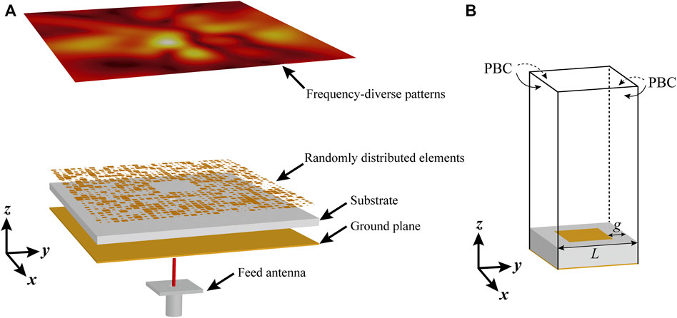
FIGURE 1. (A) Perspective view of the proposed FDHM antenna. (B) Full-wave simulation model of the element.
According to the design principle of holographic metasurface (Patel and Grbic, 2011) (Pandi et al., 2015), the surface impedance of the element should be determined first. In this design, a commercial eigen solver based on the finite element method is utilized to figure out the operating frequency under a given phase delay. The simulation model is depicted in Figure 1B with the periodic value of L = 2.2 mm and gap g between the patch and the period. The periodic boundary condition (PBC) is set in the simulator to model infinite planar metasurfaces. Substrate parameters are described as mentioned above. Due to the symmetric property of the square patch, only phase delay ϕ on the x-axis is analyzed. We assign various phase delays in the simulator to solve the eigen frequencies. Moreover, different gaps are also studied to verify that the frequency-diverse surface impedance can be realized as random elements are applied. Once the eigen frequency fe is calculated for a given phase delay ϕ and gap, the effective surface impedance can be expressed as (Fong et al., 2010) follows:
where Z0 is the free space impedance, c is the light speed, and L is the period of the element.
Near-Field Microwave Computational Imaging System
Based on the proposed FDHM antenna and microwave CI technique, a near-field imaging system is established, as shown in Figure 2. As it can be observed from the scheme, the FDHM antenna as a transmitter (Tx) and a standard horn antenna working at K-band as a receiver (Rx) are the critical components of this system. A basic operation principle is first described, and the microwave CI technique using the frequency-diverse method is then detailed.
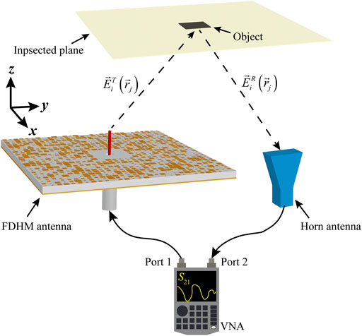
FIGURE 2. Near-field microwave CI system based on the FDHM antenna and CS theory.
Generally, microwave CI can be completed in two parts: data acquisition and data post-process. By using the proposed system, data acquisition for post-process is simply measured by a vector network analyzer (VNA). Port one connects the FDHM antenna, while Port two connects the horn antenna. The two antennas are located at the xoy-plane. Here, we assume Port 1 as Tx and Port 2 as Rx. Therefore, the measured S21 contains the required data for image restoration, which is labeled as y. At the inspected plane, the frequency-diverse patterns from Tx sense this area for each inspected voxel.
We detail the positions of the Tx, the Rx, and the inspected plane. As illustrated in Figure 2, the center of the Tx is located at (0, −35, 0) mm with the aperture size of 66 mm × 66 mm, the center of the Rx is located at (0, 10, 0) mm with the aperture size of 16 mm × 22 mm, and the inspected plane is located at (0, 0, 200) mm with the size of 400 mm × 400 mm. The height of the inspected plane is 200 mm, which lies in the Fresnel near field of the Tx/Rx antennas. We emphasize that the FDHM antenna has randomly distributed patterns in the three-dimensional space in the near field. Thus, the inspected plane in Figure 2 located inclined above the proposed antenna also possesses randomly sensing ability.
The reflected signals are captured by Rx and recorded by VNA. When the first born approximation and diffraction-limited imaging, denoted as x, are satisfied, the fields of Tx and Rx form the measurement matrix H. Then, a matrix representation is applied for data post-process, as follows (Imani et al., 2020) (Cossairt et al., 2013):
where M is the number of sensing measurements and N is the number of target voxels. As aforementioned, the sensing matrix H is built by
where m = 1 ... M, and n = 1 ... N. As implied by the CS theory, for a compressible image, the reconstruction can be achieved even though M < N. For this linear inverse problem, iterative shrinkage/thresholding algorithms are effective for realizing imaging restoration (Donoho, 2006) (Bioucas–Dias and Figueiredo, 2007).
Recognizing materials from background is a characterized capability of microwave imaging which is different from imaging in optics. Thereby, for the proposed imaging system, S-parameter calibration is required, that is (Amineh et al., 2011),
where
Results
Frequency-Diverse Radiation Patterns
Prior to conducting the imaging reconstruction, the randomly distributed patterns in the frequency domain of the FDHM antenna are examined. First, the surface impedance of the square element versus frequency for various gaps is calculated and plotted in Figure 3A. As it can be seen, within the operating band, for each frequency point, distinct gaps are related to different surface impedances. More importantly, for a given gap, the corresponding surface impedance varies with frequency. These characteristics provide the possibility of realizing frequency-diverse patterns through the surface impedance modulation. We mentioned that when the gap is zero, the element shows very high surface impedance because it only supports the guided mode in this case. Therefore, increasing the ratio of this element in an FDHM antenna would increase the surface wave modulation capability accordingly.
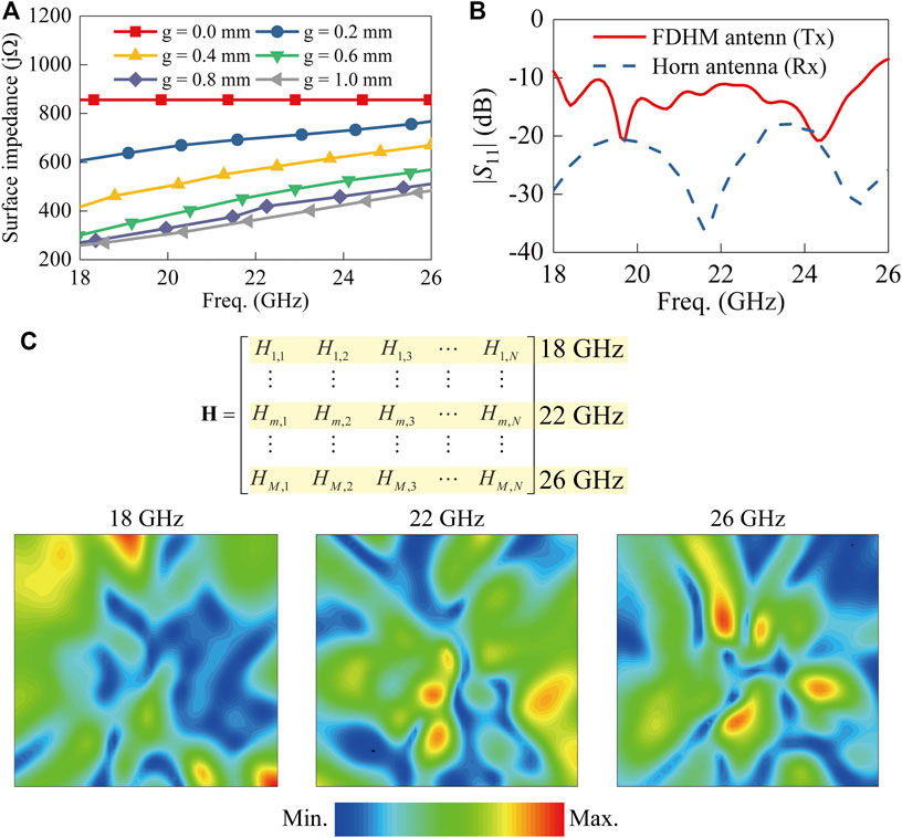
FIGURE 3. (A) Surface impedance versus frequency for various gaps. (B) Simulated return losses for the FDHM antenna and horn antenna. (C) Randomly distributed sensing patterns at different frequencies.
Without loss of generality, in this design, we use a pseudorandom number generator to construct the element distribution of the FDHM antenna. The FDHM antenna and horn antenna are simulated in Altair FEKO to obtain return losses (|S11|) and near-field radiation patterns. The simulated return losses are plotted in Figure 3B. From the results, the |S11| < −10 dB can be achieved within the working frequency band except for several frequencies at both sides of the band for the FDHM antenna. The results stated that the designed antenna and the standard horn antenna are capable of radiating EM waves effectively. Next, sensing matrix H is built with the near-field electric field (E-field) of the two antennas using (3). The sampling grid number is selected as 51 × 51, that is, N = 2,601. Randomly distributed sensing patterns at 18 GHz, 22 GHz, and 26 GHz are selected and plotted in Figure 3C. Besides, the corresponding sensing frequencies in the measurement matrix are also illustrated for better recognition. The simulated frequency points are M = 81, covering K-band from 18 to 26 GHz with 0.1 intervals. The achieved compressed ratio of this system is about 30:1, which can be calculated by N/M = 51 × 51/81 = 32.11:1 ≈ 30:1.
We further investigate the mutual coherence of the sensing matrix, which is defined as
where
Imaging Reconstruction
To demonstrate our near-field imaging system, we conduct theoretical imaging reconstruction to test the sensing matrix and a full-wave imaging reconstruction simulation to verify this system with a realistic metallic object. The two experiments can be applied to confirm each other. The theoretical imaging reconstruction is to build an ideal imaging for vector xideal with zero and one distribution. Element zero stands for free space, while element one stands for the perfect electric conductor (PEC) object. By using this ideal imaging, we could obtain theoretical ytheo for comparison. ytheo is obtained by multiplying the sensing matrix H by ideal imaging xtheo using (2). In the full-wave imaging reconstruction, a real PEC object located at an identical position as ideal imaging is set in the model. The simulated ysimu using (4) should agree well with ytheo. By solving (2), it is found that ytheo and ysimu are corresponding to xtheo and xsimu, respectively. The mean-squared error (MSE) is defined between the ideal image and recovered image, which is expressed as
where
A square object within the inspected plane is first calculated. The designed object has 5 × 5 voxels which are assigned at the center of the inspected plane, as shown in Figure 4A. The magnitude of the calculated ytheo and simulated ysimu are plotted in Figure 4B. As can be seen, the theoretical signals are in line with the simulated ones. The result confirms that the full-wave simulation model is correctly described by the math representation. The size of the square PEC object in the full-wave simulation model is 30 mm × 30 mm. Figure 4C and Figure 4D report the reconstructed imaging of xtheo and xsimu. The calculated MSEs of xtheo and xsimu to xideal are 0.0058 and 0.0075, respectively, which are comparable to the results of the existing literature (Lipworth et al., 2013).
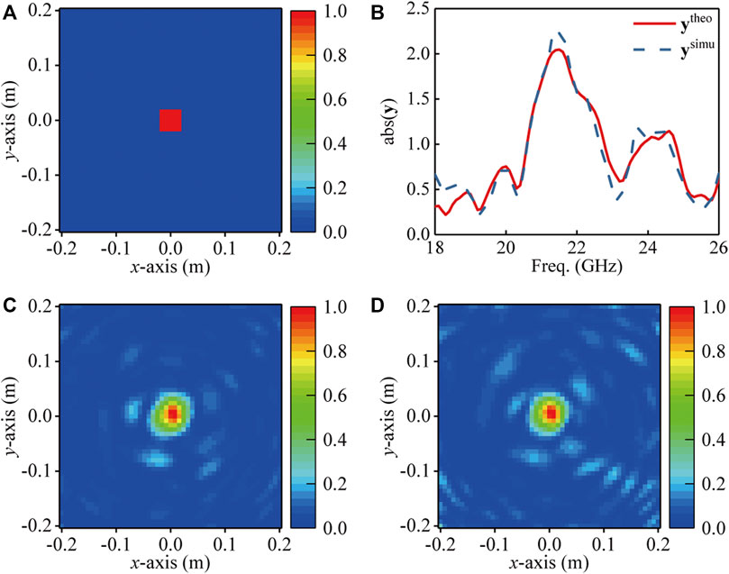
FIGURE 4. (A) Square PEC object. (B) Comparison of the calculated ytheo and simulated ysimu. (C) The reconstructed imaging xtheo using ytheo. (D) The reconstructed imaging xsimu using ysimu.
Next, a triangle PEC object is further demonstrated, as shown in Figure 5A. Good agreement of ytheo and ysimu is obtained and plotted in Figure 5B. The reconstructed results of xtheo and xsimu are shown in Figure 5C and Figure 5D, respectively. And the MSEs of xtheo and xsimu are 0.0073 and 0.0085, respectively. From the MSEs of square and triangle objects, it is found that when the shape of the object becomes complex, the recovered errors would increase accordingly.
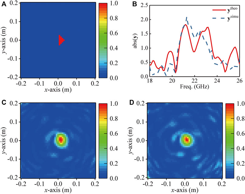
FIGURE 5. (A) Triangle PEC object. (B) Comparison of the calculated ytheo and simulated ysimu. (C) The reconstructed imaging xtheo using ytheo. (D) The reconstructed imaging xsimu using ysimu.
Finally, two square PEC objects are designed to examine the possibility of reconstructing multiple objects, as shown in Figure 6A. Also, we report the comparison of the calculated ytheo and simulated ysimu, as shown in Figure 6B. What stands out in this case is the obvious difference between theoretical and simulated signals. The recovered two objects of xtheo and xsimu are plotted in Figure 6C and Figure 6D, respectively. The corresponding MSEs of xtheo and xsimu are 0.0238 and 0.0535, respectively, which are apparently higher than those in the previous single object cases.
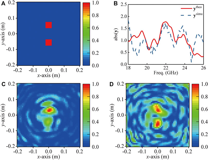
FIGURE 6. (A) Two square PEC objects (B) Comparison of the calculated ytheo and simulated ysimu. (C) The reconstructed imaging xtheo using ytheo. (D) The reconstructed imaging xsimu using ysimu.
Discussion
Observing the above three experiments, basically, the desired near-field CI based on the FDHM antenna is achieved. For single PEC object recovery, excellent results can be observed, and the calculated MSEs also verify the quality of the experiments. As the shape of the weak scatter object becomes complex, it is difficult to clearly reconstruct the boundary of the object. This can be indicated by the slightly increased MSEs.
Nevertheless, in the dual object case, the high MSEs and the discrepancy of theoretical and simulated signals are found, which can be attributed to the increasing diffraction of multiple objects. When the inspected objects are not weak scatters (larger object or multiple objects), artifacts would appear, thus reducing imaging quality. Increasing sensing quantity M would be a possible solution to this issue. In addition, increasing the distance between objects and Tx/Rx antennas might make the scatter field weaker than the near distance. However, as the inspected plane moves forward, the diversity of the sensing patterns also declines. Therefore, a trade-off between compressible sampling and weak scatter condition should be considered in the CS-based microwave CI system.
The main contribution of this article is the demonstration of the feasibility of achieving CI by the FDHM antenna. Even though the demonstration is conducted by numeric analyses, various previous articles indicate that the commercial full-wave simulation software could model practical antennas with a quite high accuracy. In future work, experimental validation will be performed.
Conclusion
This article has successfully demonstrated the feasibility and effectiveness of the FDHM antenna for microwave CI. An FDHM antenna with randomly distributed surface impedance tunable elements is proposed and validated by full-wave simulation. Based on this antenna, a near-field CI system using frequency domain data is presented. The detailed operation principle of this system and the math representation are elaborated. Further, we show the theoretical imaging reconstruction and full-wave simulation imaging reconstruction by using this system. Good agreement is obtained between the two methods, validating our FDHM antenna and the CS theory for the CI system. A single PEC object with a square or triangle shape and two square PEC objects are properly recovered. We could conclude that microwave CI systems centered on the CS technique and the holographic metasurface can challenge conventional microwave imaging systems and produce cost-effective and high-efficient devices.
Data Availability Statement
The original contributions presented in the study are included in the article/Supplementary Material; further inquiries can be directed to the corresponding author.
Author Contributions
JH and LL proposed the idea. JH, TS, XM, and QF conceived and performed the metasurface antenna design and built the imaging system. HL, YZ, and GS guided the data post-process. All authors analyzed and discussed the results.
Funding
This work was supported in part by the National Natural Science Foundation of China under Grant No. 62001342, in part by the Joint Foundation of Key Laboratory of Shanghai Jiao Tong University-Xidian University, Ministry of Education under Grant No. LHJJ/2020-02, and in part by the Fundamental Research Funds for the Central Universities under Grant No. XJS200207.
Conflict of Interest
The authors declare that the research was conducted in the absence of any commercial or financial relationships that could be construed as a potential conflict of interest.
Publisher’s Note
All claims expressed in this article are solely those of the authors and do not necessarily represent those of their affiliated organizations, or those of the publisher, the editors, and the reviewers. Any product that may be evaluated in this article, or claim that may be made by its manufacturer, is not guaranteed or endorsed by the publisher.
References
Amineh, R. K., Ravan, M., Khalatpour, A., and Nikolova, N. K. (2011). Three-Dimensional Near-Field Microwave Holography Using Reflected and Transmitted Signals. IEEE Trans. Antennas Propagat. 59 (12), 4777–4789. doi:10.1109/TAP.2011.2165496
Bioucas-Dias, J. M., and Figueiredo, M. A. T. (2007). A New TwIST: Two-step Iterative Shrinkage/Thresholding Algorithms for Image Restoration. IEEE Trans. Image Process. 16 (12), 2992–3004. doi:10.1109/TIP.2007.909319
Cossairt, O., Gupta, M., and Nayar, S. K. (2013). When Does Computational Imaging Improve Performance. IEEE Trans. Image Process. 22 (2), 447–458. doi:10.1109/TIP.2012.2216538
Donoho, D. L. (2006). Compressed Sensing. IEEE Trans. Inform. Theor. 52, 1289–1306. doi:10.1109/TIT.2006.871582
Duarte, M. F., Davenport, M. A., Takhar, D., Laska, J. N., Sun, T., Kelly, K. F., et al. (2008). Single-pixel Imaging via Compressive Sampling. IEEE Signal. Process. Mag. 25 (2), 83–91. doi:10.1109/MSP.2007.914730
Fong, B. H., Colburn, J. S., Ottusch, J. J., Visher, J. L., and Sievenpiper, D. F. (2010). Scalar and Tensor Holographic Artificial Impedance Surfaces. IEEE Trans. Antennas Propagat. 58 (10), 3212–3221. doi:10.1109/TAP.2010.2055812
Fromenteze, T., Yurduseven, O., Boyarsky, M., Gollub, J., Marks, D. L., and Smith, D. R. (2017). Computational Polarimetric Microwave Imaging. Opt. Express 25 (22), 27488. doi:10.1364/OE.25.027488
Fromenteze, T., Yurduseven, O., Imani, M. F., Gollub, J., Decroze, C., Carsenat, D., et al. (2015). Computational Imaging Using a Mode-Mixing Cavity at Microwave Frequencies. Appl. Phys. Lett. 106 (19), 194104. doi:10.1063/1.4921081
Han, J., Li, L., Ma, X., Feng, Q., Zhao, Y., and Liao, G. (2021). A Holographic Metasurface Based on Orthogonally Discrete Unit-Cell for Flexible Beam Formation and Polarization Control. Antennas Wirel. Propag. Lett. 20 (10), 1893–1897. doi:10.1109/LAWP.2021.3099574
Han, J., Li, L., Ma, X., Gao, X., Mu, Y., Liao, G., et al. (2021). Adaptively Smart Wireless Power Transfer Using 2-Bit Programmable Metasurface. IEEE Trans. Ind. Electron., 1. doi:10.1109/TIE.2021.3105988
Han, J., Li, L., Tian, S., Liu, G., Liu, H., and Shi, Y. (2020). Millimeter-Wave Imaging Using 1-Bit Programmable Metasurface: Simulation Model, Design, and Experiment. IEEE J. Emerg. Sel. Top. Circuits Syst. 10 (1), 52–61. doi:10.1109/JETCAS.2020.2973466
Hunt, J., Driscoll, T., Mrozack, A., Lipworth, G., Reynolds, M., Brady, D., et al. (2013). Metamaterial Apertures for Computational Imaging. Science 339 (6117), 310–313. doi:10.1126/science.1230054
Hunt, J., Gollub, J., Driscoll, T., Lipworth, G., Mrozack, A., Reynolds, M. S., et al. (2014). Metamaterial Microwave Holographic Imaging System. J. Opt. Soc. Am. A. 31 (10), 2109. doi:10.1364/JOSAA.31.002109
Imani, M. F., Gollub, J. N., Yurduseven, O., Diebold, A. V., Boyarsky, M., Fromenteze, T., et al. (2020). Review of Metasurface Antennas for Computational Microwave Imaging. IEEE Trans. Antennas Propagat. 68 (3), 1860–1875. doi:10.1109/TAP.2020.2968795
Li, L., Zhang, P., Cheng, F., Chang, M., and Cui, T. J. (2021). An Optically Transparent Near-Field Focusing Metasurface. IEEE Trans. Microwave Theor. Tech. 69 (4). doi:10.1109/tmtt.2021.3061475
Li, L., Zhang, X., Song, C., Zhang, W., Jia, T., and Huang, Y. (2021). Compact Dual-Band, Wide-Angle, Polarization- Angle -Independent Rectifying Metasurface for Ambient Energy Harvesting and Wireless Power Transfer. IEEE Trans. Microwave Theor. Techn. 69 (3), 1518–1528. doi:10.1109/TMTT.2020.3040962
Lipworth, G., Hunt, John., Mrozack, Alex., Brady, David., and Smith, David. R. (2013). Metamaterial Apertures for Coherent Computational Imaging on the Physical Layer. J. Opt. Soc. Amer. A, Opt. Image Sci. 30 (8). doi:10.1109/comcas.2013.6685286
Lopez-Sahcnez, J. M., and Fortuny-Guasch, J. (2000). 3-D Radar Imaging Using Range Migration Techniques. IEEE Trans. Antennas Propagat. 48 (5), 728–737. doi:10.1109/8.855491
Moreira, A., Prats-Iraola, P., Younis, M., Krieger, G., Hajnsek, I., and Papathanassiou, K. P. (2013). A Tutorial on Synthetic Aperture Radar. IEEE Geosci. Remote Sens. Mag. 1 (1), 6–43. doi:10.1109/MGRS.2013.2248301
Pandi, S., Balanis, C. A., and Birtcher, C. R. (2015). Design of Scalar Impedance Holographic Metasurfaces for Antenna Beam Formation with Desired Polarization. IEEE Trans. Antennas Propagat. 63 (7), 3016–3024. doi:10.1109/TAP.2015.2426832
Patel, A. M., and Grbic, A. (2011). A Printed Leaky-Wave Antenna Based on a Sinusoidally-Modulated Reactance Surface. IEEE Trans. Antennas Propagat. 59 (6), 2087–2096. doi:10.1109/TAP.2011.2143668
Pulido-Mancera, L., Fromenteze, T., Sleasman, T., Boyarsky, M., Imani, M. F., Reynolds, M., et al. (2016). Application of Range Migration Algorithms to Imaging with a Dynamic Metasurface Antenna. J. Opt. Soc. Am. B 33 (10), 2082. doi:10.1364/JOSAB.33.002082
Sheen, D. M., McMakin, D. L., and Hall, T. E. (2001). Three-dimensional Millimeter-Wave Imaging for Concealed Weapon Detection. IEEE Trans. Microwave Theor. Techn. 49 (9), 1581–1592. doi:10.1109/22.942570
Sleasman, T., Boyarsky, M., Imani, M. F., Gollub, J. N., and Smith, D. R. (2016). Design Considerations for a Dynamic Metamaterial Aperture for Computational Imaging at Microwave Frequencies. J. Opt. Soc. Am. B 33 (6), 1098. doi:10.1364/JOSAB.33.001098
Sleasman, T., F. Imani, M., Gollub, J. N., and Smith, D. R. (2015). Dynamic Metamaterial Aperture for Microwave Imaging. Appl. Phys. Lett. 107 (20), 204104. doi:10.1063/1.4935941
Keywords: holographic metasurface, computational imaging, compressed sensing, near-field imaging, frequency-diverse
Citation: Han J, Li L, Tian S, Ma X, Feng Q, Liu H, Zhao Y and Liao G (2021) Frequency-Diverse Holographic Metasurface Antenna for Near-Field Microwave Computational Imaging. Front. Mater. 8:766889. doi: 10.3389/fmats.2021.766889
Received: 30 August 2021; Accepted: 13 September 2021;
Published: 19 October 2021.
Edited by:
Wei-Xiang Jiang, Southeast University, ChinaCopyright © 2021 Han, Li, Tian, Ma, Feng, Liu, Zhao and Liao. This is an open-access article distributed under the terms of the Creative Commons Attribution License (CC BY). The use, distribution or reproduction in other forums is permitted, provided the original author(s) and the copyright owner(s) are credited and that the original publication in this journal is cited, in accordance with accepted academic practice. No use, distribution or reproduction is permitted which does not comply with these terms.
*Correspondence: Long Li, lilong@mail.xidian.edu.cn