Pile Caps Design,Reinforcement Calculation And Details
The results of a geotechnical study may recommend using supported foundations for a heavily loaded building.
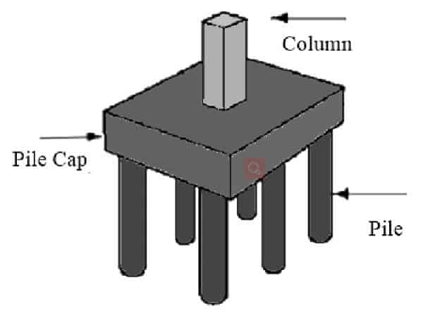
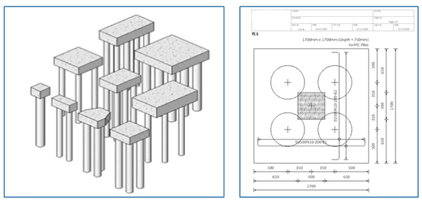
These piles are connected on top with a pile cap, which takes all the building load and transfers it to the piles below. The dimension of the pile cap certainly depends on the number of piles, it should be capping.
The arrangement and number of piles are determined using un factored moment and forces, that are transmitted to piles, based on which allowable pile capacity is selected through geotechnical engineering basics. The spacing of piles is usually a function of the type of piles and their capacity.
In this article, we will discuss how to design a pile cap.
The article will not discuss any design formulations, instead, it will enlighten you about the rationale behind various design steps.
Contents
Predesign Phase
By approximating the plan dimension which is based on several piles, the thickness of the cap can be determined considering shear and flexural loads at the most critical cross-sections.
According to the North American code of concrete ACI 318-08, the pile cap thickness is determined initially on the following parameters:
- One-way shear requirements at the column
- Two-way shear requirements around the column
- Pile cap overall depth minimum requirements
- One-way and two-way shear requirements around the piles
Calculating the flexure strength and reinforcement
Flexural moments are evaluated in two orthogonal directions (Mx and My) in a plane during a cap design process.
To simplify the design process, an average value of reinforcement calculated considering the flexure moment requirement in each direction is used. Therefore, the size and spacing of flexure reinforcement are the same in both orthogonal directions.
To determine the area of steel, the flexure method is used. In which the flexure stress diagram is made. The neutral axis is located.
Using which, it decided which part is in compression or tension, and accordingly, the amount of reinforcement is balanced.
Concrete usually takes most of the compression load, while its capacity in compression is neglected.
Development length of reinforcement bars
After you have calculated the area of reinforcements, the next step is to calculate the development length of the bars.
They must be developed properly within the concrete to perform the intended design application. Provision of appropriate development length ensures that bars will not slip out of the concrete when experiencing the tension forces.
The concept of using development length is as follows: minimum lengths of reinforcement must be present beyond the points of peak stress (critical sections) in the reinforcement to fully develop the bars
Concrete cover
After designing the reinforcement, the next step is to decide on a suitable concrete cover. The cover protects the reinforcement from corrosion and external wear and tear.
As per ACI 318 requirements, the cover should not be less than 50 mm for surfaces that are in contact with the earth’s face (soil), while it should not be less than 40 mm for the externally exposed surfaces.
However, in cases when concrete is in direct contact with soil in the liquid state, the cover should be at least 75mm. This is particularly the case of pouring lean concrete on the soil surface directly. So in the case of in situ piles, the covers should be at least 75 mm while in the case of precast piles, it should be at least 50 mm.
Pile Cap Rebar Detailing
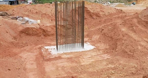
Minimum reinforcement
Apart from calculating the reinforcement from the flexure diagram, there are certain stipulations on the minimum amount f reinforcement that should be present in the pile cap.
ACI 318 gives guidelines on minimum steel areas that should be present in the concrete. Ideally, the diameter of the main reinforcing bars should not be less than 10 mm.
Distribution of reinforcement
Total reinforcement should be distributed across the corresponding resisting section of a pile cap as follow:
- The reinforcement should be spread uniformly across the full width of the pile cap in case of one-way reinforced footing.
- The reinforcement should be extended in each direction uniformly in case of a two-way reinforced square pile cap.
- Similar to the previous two cases, the reinforcement should also be distributed uniformly in the case of a rectangular shape pile cap. For shorter direction reinforcement, a central band equal to the breadth of the pile cap shall be marked along the length of the cap, while the reinforcement in the longer direction should be spread uniformly across the full width of the pile cap.
Detailing of the reinforcement
Apart from following the previously listed design requirements, the pile caps should follow the following detailing requirements for the reinforcement.
- The longitudinal bars resisting flexure loads should be of the same length. There should be a properly welded lap joint that can fit tightly into the pile shoe if there is one.
Bars of shorter direction may also be employed at locations of extreme bending moments. But they should be carefully detailed to avoid any sudden discontinuity.
- Lateral reinforcement, sometimes, also called shear reinforcement can be in the form of hoop or links. They should have at least a diameter of 6mm or more. They are usually provided to resist shear loads, which are usually less.
Additionally, they also serve as the restrain to the longitudinal reinforcement. Following recommendations should be followed for the shear reinforcement:
- They should no be less than 0.6% At each end of the pile for a distance of about 3 times the least width.
- They should be spaced wide enough to allow free movement of concrete around them. The transition between the narrow spacing of shear reinforcement, which is usually at the ends to the maximum spacing should be gradually done over a length of 3 times the least width of the pile cap.
Pile Caps Made With Lean Concrete
Lean concrete is a mix of concrete, in which the amount of cement present is lower than the water present in its strata.
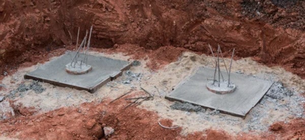
To make the concrete leaner, usually aggregate/cement ratio is increased. As a result, less quantity of paste is available for providing lubrication, per unit surface of aggregate and therefore the mobility of aggregate is restricted.
Pile caps are often made with lean concrete. In this case, excavation is first made in the ground as per the size of the pile cap. Then lean concrete is poured down. Before pouring down the lean concrete, reinforcement mesh is placed.
Precast Pile Caps
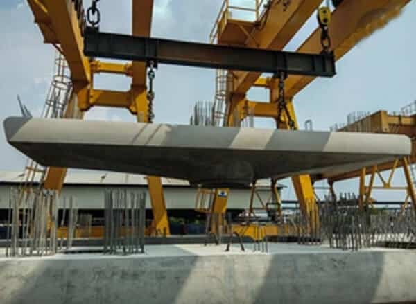
In contrast to pile caps made with lean concrete, which is an in situ method. They can also be precast. In this case, the cap is prefabricated in the factory and supplied to the building site, where it is joined together with the pile. The joint between piles and their cap is properly made to ensure proper load transfer.
To make the concrete leaner, usually aggregate/cement ratio is increased. As a result, less quantity of paste is available for providing lubrication, per unit surface of aggregate and therefore the mobility of aggregate is restricted.
Pile caps are often made with lean concrete. In this case, excavation is first made in the ground as per the size of the pile cap. Then lean concrete is poured down. Before pouring down the lean concrete, reinforcement mesh is placed.
Conclusions
To conclude, in this article we discussed the design process of pile caps, their reinforcement details and limitations, and lastly different methods of making the pile caps.
The design steps highlighted in this article are the same more or less in all building codes worldwide while the formulations may differ among them. Hence you will get to know all about the pile caps.




Leave A Comment