
Related Manuals for Areca ARC-1880 Series


Summary of Contents for Areca ARC-1880 Series
- Page 1 6Gb/s SAS RAID Cards ARC-1880 Series (PCIe 2.0 to 6Gb/s SAS RAID Controllers) USER’S Manual Version: 1.2 Issue Date: October, 2013...
- Page 2 Manufacturer’s Declaration for CE Certification We confirm ARC-1880 series have been tested and found comply with the requirements set up in the council directive on the approximation of the low of member state relating to the EMC Directive2004/108/EC.
-
Page 3: Table Of Contents
Contents 1. Introduction .............. 10 1.1 Overview ............... 10 1.2 Features ................ 12 2. Hardware Installation ..........16 2.1 Before You First Installing..........16 2.2 Board Layout ..............16 2.3 Installation ..............23 2.4 SAS Cables ..............30 2.4.1 Internal Min SAS 4i to SATA Cable ....... 30 2.4.2 Internal Min SAS 4i to 4xSFF-8482 Cable ....... - Page 4 3.7.3 Volume Set Function ........... 60 3.7.3.1 Create Volume Set (0/1/10/3/5/6) ......61 • Volume Name ..............63 • Capacity ............... 64 • Stripe Size ..............66 • SCSI Channel ..............66 • SCSI ID ................ 67 • Cache Mode ..............68 •...
- Page 5 3.7.7 Ethernet Configuration ..........90 3.7.7.1 DHCP Function ............90 3.7.7.2 Local IP address ............ 91 3.7.7.3 HTTP Port Number ..........92 3.7.7.4 Telnet Port Number ..........92 3.7.7.5 SMTP Port Number ..........93 3.7.8 View System Events ........... 94 3.7.9 Clear Events Buffer .............
- Page 6 • Start-up McRAID Storage Manager Through Ethernet Port (Out-of-Band) ............... 120 6.2 6Gb/s SAS RAID controller McRAID Storage Manager ..121 6.3 Main Menu ..............122 6.4 Quick Function .............. 122 6.5 Raid Set Functions ............123 6.5.1 Create Raid Set ............123 6.5.2 Delete Raid Set ............
- Page 7 • Background Task Priority ..........141 • JBOD/RAID Configuration ..........141 • SATA NCQ Support ............141 • HDD Read Ahead Cache ..........141 • Volume Data Read Ahead ..........141 • HDD Queue Depth ............142 • Empty HDD Slot LED ............ 142 •...
- Page 8 A. Device Event .............. 176 B. Volume Event ............. 177 C. RAID Set Event ............178 D. Hardware Monitor Event ..........178 Appendix E ..............180 RAID Concept ..............180 RAID Set ................. 180 Volume Set ..............180 Ease of Use Features ............181 •...
-
Page 10: Introduction
INTRODUCTION 1. Introduction This section presents a brief overview of the 6Gb/s SAS RAID control- ler, ARC-1880 series. (PCIe 2.0 to 6Gb/s SAS RAID controllers) 1.1 Overview SAS 2.0 is designed for much higher speed data transfer than pre- vious available and backward compatibility with SAS 1.0. The... - Page 11 INTRODUCTION of ECC DDR2-800 registered SDRAM, upgrade to 4GB. The optional battery backup module provides power to the cache if it contains data not yet written to the drives when power is lost. The test result is against overall performance compared to other 6Gb/s SAS RAID controllers.
-
Page 12: Features
INTRODUCTION ucts and technology are based on extensive testing and validation process; leverage Areca SAS or SATA RAID controller field-proven compatibility with operating systems, motherboards, applications and device drivers. Easy RAID Management The controllers contain an embedded McBIOS RAID manager that can access via hot key at M/B BIOS boot-up screen. - Page 13 INTRODUCTION RAID Features • RAID level 0, 1, 10(1E), 3, 5, 6, 30, 50, 60, Single Disk or JBOD • Multiple RAID selection • Online array roaming • Offline RAID set • Online RAID level/stripe size migration • Online capacity expansion and RAID level migration simultane- ously •...
- Page 14 • VMware • Solaris 10/11 x86/x86_64 • Mac OS 10.4.x/10.5.x/10.6.x (For latest supported OS listing visit http://www.areca.com.tw) Important Be sure to update the ArcMSR.kext driver shipping with Mac OS X to V1.3.7 or later from the software CD or from the Areca website.
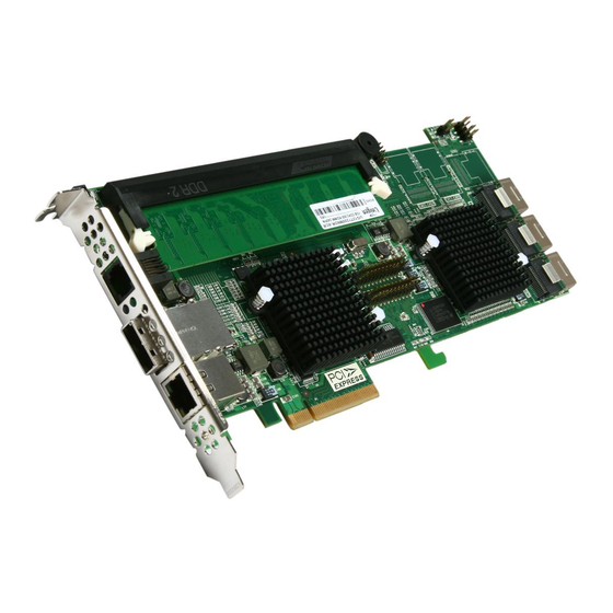
- Page 15 INTRODUCTION 6Gb/s SAS RAID controllers Model name ARC-1880i ARC-1880LP ARC-1880x I/O Processor RAID-on-Chip 800MHz Form Factor(H x L) Low Profile: 64.4 x 169.5 mm Host Bus Type PCIe 2.0 x8 Lanes Driver Connector 2xSFF-8087 1xSFF-8087 2xSFF-8088 1xSFF-8088 Drive Support Up to 128 6Gb/s and 3Gb/s SAS/SATA HDDs RAID Level 0, 1, 1E, 3, 5, 6, 10, 30, 50, 60, Single Disk, JBOD On-Board Cache...
-
Page 16: Hardware Installation
HARDWARE INSTALLATION 2. Hardware Installation This section describes the procedures for installing the 6Gb/s SAS RAID controllers. 2.1 Before You First Installing Thanks for purchasing the 6Gb/s SAS RAID controller as your RAID data storage subsystem. This user manual gives simple step-by- step instructions for installing and configuring the 6Gb/s SAS RAID controller. - Page 17 SAS 13-16 Ports (Internal) SFF-8087 13. (SCN4) SAS 9-12 Ports (Internal) SFF-8087 14. (SCN5) SAS 5-8 Ports (Internal) SFF-8087 15. (SCN6) SAS 1-4 Ports (Internal) SFF-8087 Table 2-1, ARC-1880ix-12/16/24 connectors Note: *1: You can download the ARC1880ix_1882ix Expander-CLI. PDF manual from http://www.areca.com.tw/support/main. htm.
- Page 18 HARDWARE INSTALLATION Figure 2-2, ARC-1880i 6Gb/s SAS RAID controller Connector Type Description 1. (J7) Ethernet Port RJ45 2. (J6) Individual Fault LED Header 4-pin header 3. (J5) Individual Activity (HDD) LED Header 4-pin header 4. (J4) Global Fault/Activity LED 4-pin header 5.
- Page 19 HARDWARE INSTALLATION Figure 2-3, ARC-1880LP 6Gb/s SAS RAID controller Connector Type Description 1. (J2) Battery Backup Module Connector 12-pin box header 2. (J1) Manufacture Purpose Port 10-pin header 3. (J6) Global Fault/Activity LED 4-pin header 4. (J3) I2C/LCD Connector 8-pin header 5.
- Page 20 SAS 1-4 Ports (External) SFF-8088 7. (SCN2) SAS 5-8 Ports (External) SFF-8088 Table 2-4, ARC-1880x connectors The following describes the ARC-1880 series link/activity LED. Status Link LED When link LED illuminate that indicates the link LED is (Green light) connected.
- Page 21 HARDWARE INSTALLATION Front Side Back Side Figure 2-5, ARC-1880ixl-8/12 6Gb/s SAS RAID controller Connector Type Description Front Side 1. (J5) Ethernet port RJ45 2. (SCN4) SAS 5-8 Ports (External) SFF-8088 3. (J2) Battery Backup Module Connector 12-pin box header 4. (J1) Manufacture Purpose Port 10-pin header 5.
- Page 22 The 6Gb/s SAS RAID controller can be installed in a universal PCIe slot and requires a motherboard that: ARC-1880 series 6Gb/s SAS RAID controller requires: • Comply with the PCIe 2.0 x8 lanes It can work on the PCIe 2.0 x1, x4, x8, and x16 signal with x8 or x16 slot M/B.
-
Page 23: Installation
HARDWARE INSTALLATION • Before opening the system cover, turn off power switches and unplug the power cords. Do not reconnect the power cords until you have replaced the covers. Electrostatic Discharge Static electricity can cause serious damage to the electronic com- ponents on this 6Gb/s SAS RAID controller. - Page 24 HARDWARE INSTALLATION Step 4. Install the PCIe 6Gb/s SAS RAID Cards To install the 6Gb/s SAS RAID controller, remove the mounting screw and existing bracket from the rear panel behind the selected PCIe 2.0 slot. Align the gold-fingered edge on the card with the selected PCIe 2.0 slot.
- Page 25 HARDWARE INSTALLATION In the backplane solution, SAS/SATA drives are directly connected to 6Gb/s SAS system backplane or through an expander board. The number of SAS/SATA drives is limited to the number of slots available on the backplane. Some backplanes support daisy chain expansion to the next backplanes.
- Page 26 HARDWARE INSTALLATION Step 6. Install SAS Cable This section describes SAS cable how to connect on controller. Figure 2-7, SAS cable connect to HD Figure 2-8, SAS cable connect to backplane...
- Page 27 The SFF-8087 to 4 SATA with sideband cable which follows SFF-8448 specification. The SFF-8448 sideband signals cable is reserved for the backplane with header on it.The following signal defines the sideband connector which can work with Areca sideband cable on its SFF-8087 to 4 SATA cable.
- Page 28 HARDWARE INSTALLATION The sideband header is located at backplane. For SGPIO to work properly, please connect Areca 8-pin sideband cable to the sideband header as shown above. See the table for pin definitions. Note: For lastest release versions of drivers, please download from http://www.areca.com.tw/support/main.htm...
- Page 29 HARDWARE INSTALLATION tem installation. Please refer to Chapter 4 Diver Installation for the detailed installation procedure. In an existing system: • To install the controller driver into the existing operating system. For the detailed installation procedure, please refer to the Chapter 4, Driver Installation.
-
Page 30: Sas Cables
PCIe 2.0 6Gb/s SAS RAID controller volume set. Carbon Copy Cloner is an archival type of back up software. You can take your whole Mac OS X system and make a carbon copy or clone to Areca volume set like an other hard drive. -
Page 31: Internal Min Sas 4I To 4Xsff-8482 Cable
HARDWARE INSTALLATION nal connectors, each of them can support up to four SAS/SATA drives. These controllers can be installed in a server RAID enclosure with standard SATA connectors backplane. The following diagram shows the picture of Min SAS 4i to 4*SATA cables. Backplane supports SGPIO header can leverage the SGPIO function on the 6Gb/s SAS RAID controller through the sideband cable. -
Page 32: Internal Min Sas 4I (Sff-8087) To Internal Min Sas 4I (Sff-8087) Cable
HARDWARE INSTALLATION Figure 2-10, Min SAS 4i to 4xSFF-8482 cable 2.4.3 Internal Min SAS 4i (SFF-8087) to Internal Min SAS 4i (SFF-8087) cable The 6Gb/s SAS RAID controllers have 1-6 Min SAS 4i internal SFF-8087 connectors, each of them can support up to four SAS/ SATA signals. -
Page 33: External Min Sas 4I Drive Boxes And Drive Expanders
HARDWARE INSTALLATION 2.4.4 External Min SAS 4i Drive Boxes and Drive Expanders The Min SAS 4x external cables are used for connection between the 6Gb/s SAS controller external connectors and connectors on the external drive boxes or drive expanders (JBOD). The 6Gb/s SAS controller has Min SAS 4x (SFF-8088) external connector, each of them can support up to four SAS/SATA signals. - Page 34 HARDWARE INSTALLATION Note: A cable for the global indicator comes with your computer system. Cables for the individual drive LEDs may come with a drive cage, or you may need to purchase them. A: Individual Activity/Fault LED and Global Indicator Con- nector Most of the backplane has supported the HDD activity from the HDD.
- Page 35 HARDWARE INSTALLATION If the system will use only a single global indicator, attach the LED to the two pins of the global activity/cache write-pending connector. The global fault pin pair connector is the overall fault signal. This signal will light up in any disk drive failure. The following diagrams show all LEDs, connectors and pin locations.
- Page 36 HARDWARE INSTALLATION Figure 2-15, ARC-1880LP individual LED for each channel drive and global indicator connector for computer case. Figure 2-16, ARC-1880x individual LED for each channel drive and global indicator connector for computer case. Figure 2-17, ARC-1880ixl-8/12 individual LED for each channel drive and global indicator connector for computer case.
- Page 37 HARDWARE INSTALLATION B: Areca Serial Bus Connector You can also connect the Areca interface to a proprietary SAS/ SATA backplane enclosure. This can reduce the number of activity LED and/or fault LED cables. The I C interface can also cascade to another SAS/SATA backplane enclosure for the additional channel status display.
-
Page 38: Recognizing A Drive Failure
HARDWARE INSTALLATION 2.5 Hot-plug Drive Replacement The RAID controller supports the ability of performing a hot-swap drive replacement without powering down the system. A disk can be disconnected, removed, or replaced with a different disk without taking the system off-line. The RAID rebuilding will be processed automatically in the background. - Page 39 HARDWARE INSTALLATION The software components configure and monitor the 6Gb/s SAS RAID controllers as following table. Configuration Utility Operating System supported McBIOS RAID Manager OS-Independent McRAID Storage Manager Windows 7/2008/Vista/XP/2003, Linux, (Via Archttp proxy server) FreeBSD, Solaris and Mac McRAID Storage Manager OS-Independent (Via Ethernet port) SAP Monitor (Single Admin Portal to...
- Page 40 Before launching the SNMP agent in the sever, you need first to enable the firmware-embedded SNMP community configuration and install Areca SNMP extension agent in your server system. If you need additional information about installation and start-up the function, see the SNMP Operation & Installation section in the Appendix C.
-
Page 41: Mcbios Raid Manager
ARC-1880 PCIEx8/5.0G RAID Controller - DRAM: 256(MB) / #Channels: 16 BIOS: V1.22 / Date: 2006-8-07 - F/W: V1.42 / Date: 2007-3-1 Bus/Dev/Fun= 3/0/0, I/0-Port=28000000h, IRQ=11, BIOS=C800 : 0h ID-LUN=00-0, Vol=”Areca ARC-1880-VOL#000R001”, Size=3.6 (TB) ID-LUN=00-1, Vol=”Areca ARC-1880-VOL#001R001”, Size=3.6 (TB) ID-LUN=00-2, Vol=”Areca ARC-1880-VOL#002R001”, Size=3.6 (TB) RAID controller BIOS not installed Press <Tab/F6>... -
Page 42: Mcbios Raid Manager
While the desired controller is highlighted, press the Enter key to enter the main menu of the McBIOS RAID manager. I/O Port Addr : 28000000h, F2(Tab): Select Controller, F10: Reboot System Areca Technology Corporation RAID Controller Note: Main Menu... -
Page 43: Configuring Raid Sets And Volume Sets
BIOS CONFIGURATION • Expand RAID sets, • Add physical drives, • Define volume sets, • Modify volume sets, • Modify RAID level/stripe size, • Define pass-through disk drives, • Modify system functions and • Designate drives as hot spares. 3.3 Configuring Raid Sets and Volume Sets You can configure RAID sets and volume sets with McBIOS RAID manager automatically. -
Page 44: Using Quick Volume /Raid Setup Configuration
BIOS CONFIGURATION 3.5 Using Quick Volume /Raid Setup Con- figuration “Quick Volume / Raid Setup configuration” collects all available drives and includes them in a RAID set. The RAID set you created is associated with exactly one volume set. You will only be able to modify the default RAID level, stripe size and capacity of the new volume set. -
Page 45: Using Raid Set/Volume Set Function Method
BIOS CONFIGURATION The capacity for the current volume set is entered after highlighting the desired RAID level and pressing the Enter key. The capacity for the current volume set is displayed. Use the UP and DOWN arrow keys to set the capacity of the volume set and press the Enter key to confirm. - Page 46 BIOS CONFIGURATION Step Action To setup the hot spare (option), choose “Raid Set Function” from the main menu. Select the “Create Hot Spare” and press the Enter key to define the hot spare. Choose “Raid Set Function” from the main menu. Select “Create Raid Set”...
-
Page 47: Main Menu
The main menu shows all functions that are available for executing actions, which is accomplished by clicking on the appropriate link. I/O Port Addr : 28000000h, F2(Tab): Select Controller, F10: Reboot System Areca Technology Corporation RAID Controller Main Menu Quick Volume/Raid Setup... -
Page 48: Quick Volume/Raid Setup
BIOS CONFIGURATION Option Description Quick Volume/Raid Setup Create a default configuration based on the number of physical disk installed Raid Set Function Create a customized RAID set Volume Set Function Create a customized volume set Physical Drives View individual disk information Raid System Function Setup the RAID system configuration Hdd Power Management... - Page 49 Select “Quick Volume/Raid Setup” from the main menu; all possible RAID level will be displayed on the screen. I/O Port Addr : 28000000h, F2(Tab): Select Controller, F10: Reboot System Areca Technology Corporation RAID Controller Main Menu Quick Volume/Raid Setup...
- Page 50 “Create Volume Set” option in the main menu to define additional volume sets. I/O Port Addr : 28000000h, F2(Tab): Select Controller, F10: Reboot System Areca Technology Corporation RAID Controller Main Menu Available Capacity : 2400.0GB...
- Page 51 Roaming the stripe size 256K/512K/1024K Raid Set to firm- ware version older than 1.52 will cause data corruption. I/O Port Addr : 28000000h, F2(Tab): Select Controller, F10: Reboot System Areca Technology Corporation RAID Controller Main Menu Available Capacity : 2400.0GB...
-
Page 52: Raid Set Function
Available)” for initialization and “No Init (To Rescue Volume)” for recovering the missing RAID set configuration. I/O Port Addr : 28000000h, F2(Tab): Select Controller, F10: Reboot System Areca Technology Corporation RAID Controller Main Menu Available Capacity : 2400.0GB Quick Volume/Raid Setup Selected Capacity: 2400.0GB... -
Page 53: Create Raid Set
Esc key. A “Create Raid Set Confirmation” screen will appear, select the Yes option to confirm it. I/O Port Addr : 28000000h, F2(Tab): Select Controller, F10: Reboot System Areca Technology Corporation RAID Controller Main Menu Quick Volume/Raid Setup Raid Set Function... -
Page 54: Delete Raid Set
RAID set. The max no. disk drives per volume set: 32 for RAID 0/1/10/3/5/6 and 128 for RAID 30/50/60. I/O Port Addr : 28000000h, F2(Tab): Select Controller, F10: Reboot System Areca Technology Corporation RAID Controller Main Menu Quick Volume/Raid Setup Raid Set Function... -
Page 55: Expand Raid Set
BIOS CONFIGURATION 3.7.2.3 Expand Raid Set I/O Port Addr : 28000000h, F2(Tab): Select Controller, F10: Reboot System Areca Technology Corporation RAID Controller Main Menu Quick Volume/Raid Setup Raid Set Function Raid Set Function Raid Set Function Volume Set Function Select IDE Drives For Raid Set Expansion... -
Page 56: Offline Raid Set
Unexpected accident may cause serious data corruption. • Migrating I/O Port Addr : 28000000h, F2(Tab): Select Controller, F10: Reboot System Areca Technology Corporation RAID Controller Main Menu Quick Volume/Raid Setup Raid Set Function Raid Set Function... -
Page 57: Activate Incomplete Raid Set
BIOS CONFIGURATION I/O Port Addr : 28000000h, F2(Tab): Select Controller, F10: Reboot System Areca Technology Corporation RAID Controller Main Menu Quick Volume/Raid Setup Raid Set Function Raid Set Function Raid Set Function Volume Set Function Create Raid Set Physical Drives... -
Page 58: Create Hot Spare
RAID set or enclosure with a dedicated hot spare is pre-set, data on the disk drive is rebuild automatically on the dedicated hot spare disk. I/O Port Addr : 28000000h, F2(Tab): Select Controller, F10: Reboot System Areca Technology Corporation RAID Controller Main Menu Quick Volume/Raid Setup Raid Set Function... -
Page 59: Rescue Raid Set
BIOS CONFIGURATION I/O Port Addr : 28000000h, F2(Tab): Select Controller, F10: Reboot System Areca Technology Corporation RAID Controller Main Menu Quick Volume/Raid Setup Raid Set Function Raid Set Function Raid Set Volume Set Function Delete Raid Set Physical Drives Expand Raid Set... -
Page 60: Raid Set Information
RAID set number, then press the Enter key. The “Raid Set Information” will appear. You can only view information for the RAID set in this screen. I/O Port Addr : 28000000h, F2(Tab): Select Controller, F10: Reboot System Areca Technology Corporation RAID Controller Main Menu Quick Volume/Raid Setup Raid Set Function... -
Page 61: Create Volume Set (0/1/10/3/5/6)
BIOS CONFIGURATION I/O Port Addr : 28000000h, F2(Tab): Select Controller, F10: Reboot System Areca Technology Corporation RAID Controller Main Menu Quick Volume/Raid Setup Raid Set Function Volume Set Function Volume Set Function Physical Drives Raid System Function Hdd Power Management... - Page 62 Volume Name, Raid level, Capacity, Strip Size, SCSI Channel/ SCSI ID/SCSI Lun, Cache Mode, Tagged Command Queuing. I/O Port Addr : 28000000h, F2(Tab): Select Controller, F10: Reboot System Areca Technology Corporation RAID Controller Main Menu Quick Volume/Raid Setup Volume Creation...
-
Page 63: Volume Name
BIOS CONFIGURATION I/O Port Addr : 28000000h, F2(Tab): Select Controller, F10: Reboot System Areca Technology Corporation RAID Controller Main Menu Quick Volume/Raid Setup Volume Creation Raid Set Function Volume Set Functions Volume Set Function Volume Set Function Volume Name : Volume Set # 000... -
Page 64: Capacity
Select a RAID level and press the Enter key to confirm. I/O Port Addr : 28000000h, F2(Tab): Select Controller, F10: Reboot System Areca Technology Corporation RAID Controller Main Menu Quick Volume/Raid Setup Raid Set Function... - Page 65 If volume capacity will exceed 2TB, controller will show the "Greater Two TB Volume Support" sub-menu. I/O Port Addr : 28000000h, F2(Tab): Select Controller, F10: Reboot System Areca Technology Corporation RAID Controller Greater Two TB Volume Support Main Menu Quick Volume/Raid Setup...
-
Page 66: Stripe Size
Roaming the stripe size 256K/512K/1024K Raid Set to firm- ware version older than 1.52 will cause data corruption. I/O Port Addr : 28000000h, F2(Tab): Select Controller, F10: Reboot System Areca Technology Corporation RAID Controller Main Menu Quick Volume/Raid Setup Raid Set Function... -
Page 67: Scsi Id
It is necessary to assign a SCSI ID to each device from a list of available SCSI IDs. I/O Port Addr : 28000000h, F2(Tab): Select Controller, F10: Reboot System Areca Technology Corporation RAID Controller Main Menu Quick Volume/Raid Setup... -
Page 68: Cache Mode
• Cache Mode User can set the cache mode to either “Write Through” or “Write Back”. I/O Port Addr : 28000000h, F2(Tab): Select Controller, F10: Reboot System Areca Technology Corporation RAID Controller Main Menu Quick Volume/Raid Setup Volume Creation Raid Set Function... -
Page 69: Create Raid30/50/60 (Volume Set 30/50/60)
3.7.3.1. User can modify the default values in this screen; the modification procedures are in section 3.7.3.4. I/O Port Addr : 28000000h, F2(Tab): Select Controller, F10: Reboot System Areca Technology Corporation RAID Controller Main Menu Quick Volume/Raid Setup Raid Set Function... -
Page 70: Delete Volume Set
RAID set. Move the cursor to the volume set number that is to be deleted and press the Enter key to delete it. I/O Port Addr : 28000000h, F2(Tab): Select Controller, F10: Reboot System Areca Technology Corporation RAID Controller Main Menu Quick Volume/Raid Setup Raid Set Function... - Page 71 BIOS CONFIGURATION I/O Port Addr : 28000000h, F2(Tab): Select Controller, F10: Reboot System Areca Technology Corporation RAID Controller Main Menu Volume Modification Quick Volume/Raid Setup Raid Set Function Volume Set Functions Volume Set Name : ARC-1880-VOL # 000 Volume Set Function...
-
Page 72: Check Volume Set
Power failure may damage the migration data. Please back- up the RAID data before you start the migration function. I/O Port Addr : 28000000h, F2(Tab): Select Controller, F10: Reboot System Areca Technology Corporation RAID Controller Main Menu The Volume Set Information... -
Page 73: Stop Volume Set Check
BIOS CONFIGURATION I/O Port Addr : 28000000h, F2(Tab): Select Controller, F10: Reboot System Areca Technology Corporation RAID Controller Main Menu Quick Volume/Raid Setup Raid Set Function Volume Set Functions Volume Set Function Volume Set Function Create Volume Set Select Volume To Check... -
Page 74: Physical Drives
Move the cursor bar to an item, then press Enter key to select the desired function. I/O Port Addr : 28000000h, F2(Tab): Select Controller, F10: Reboot System Areca Technology Corporation RAID Controller Main Menu Quick Volume/Raid Setup... -
Page 75: Create Pass-Through Disk
The SCSI Channel/SCSI ID/SCSI LUN, Cache Mode, and Tag Queuing must be specified to create a pass- through disk. I/O Port Addr : 28000000h, F2(Tab): Select Controller, F10: Reboot System Areca Technology Corporation RAID Controller Main Menu Quick Volume/Raid Setup Physical Drive Function... -
Page 76: Identify Selected Drive
ArrowKey Or AZ:Move Cursor, Enter: Select, ESC: Escape, L:Line Draw, X: Redraw 3.7.4.6 Identify Enclosure To prevent removing the wrong enclosure, the selected Areca expander enclosure all disks fault LED indicator will light for physically locating the selected enclosure when the “Identify Enclosure”... -
Page 77: Raid System Function
Physical Drive Information Create Pass-Through Disk Select The Enclosure Raid System Function Modify Pass-Through Disk Hdd Power Management Enclosure#1 : ARECA SAS RAID Adapter V1.0 Delete Pass-Through Disk Ethernet Configuration Enclosure#2 : Areca x28-05.75.1.37 000 Identify Selected Drive View System Events Enclosure#3 : Areca x28-05.75.1.37 000... -
Page 78: Mute The Alert Beeper
The beeper will still activate on the next event. I/O Port Addr : 28000000h, F2(Tab): Select Controller, F10: Reboot System Areca Technology Corporation RAID Controller Raid System Function Main Menu... -
Page 79: Change Password
No password checking will occur when entering the main menu. I/O Port Addr : 28000000h, F2(Tab): Select Controller, F10: Reboot System Areca Technology Corporation RAID Controller Raid System Function Main Menu Mute The Alert Beeper... -
Page 80: Background Task Priority
BIOS CONFIGURATION I/O Port Addr : 28000000h, F2(Tab): Select Controller, F10: Reboot System Areca Technology Corporation RAID Controller Raid System Function Main Menu Mute The Alert Beeper Quick Volume/Raid Setup Alert Beeper Setting Raid Set Function Change Password Volume Set Function... -
Page 81: Sata Ncq Support
The 6Gb/s SAS RAID controller allows the user to select the SATA NCQ support: “Enabled” or “Disabled”. I/O Port Addr : 28000000h, F2(Tab): Select Controller, F10: Reboot System Areca Technology Corporation RAID Controller Raid System Function Main Menu Mute The Alert Beeper... -
Page 82: Volume Data Read Ahead
The "Aggressive" value is optimal for sequential access but it degrades random access. I/O Port Addr : 28000000h, F2(Tab): Select Controller, F10: Reboot System Areca Technology Corporation RAID Controller Raid System Function Main Menu Mute The Alert Beeper... -
Page 83: Empty Hdd Slot Led
BIOS CONFIGURATION I/O Port Addr : 28000000h, F2(Tab): Select Controller, F10: Reboot System Areca Technology Corporation RAID Controller Raid System Function Main Menu Mute The Alert Beeper Quick Volume/Raid Setup Alert Beeper Setting Raid Set Function Change Password Volume Set Function... -
Page 84: Controller Fan Detection
(This function is not avail- able in the web browser setting. I/O Port Addr : 28000000h, F2(Tab): Select Controller, F10: Reboot System Areca Technology Corporation RAID Controller Raid System Function Main Menu Mute The Alert Beeper... -
Page 85: Disk Write Cache Mode
ArrowKey Or AZ:Move Cursor, Enter: Select, ESC: Escape, L:Line Draw, X: Redraw 3.7.5.14 Capacity Truncation Areca RAID controllers use drive truncation so that drives from different vendors are more likely to be usable as spares for one another. Drive truncation slightly decreases the usable capac- ity of a drive that is used in redundant units. -
Page 86: Hdd Power Management
Disabled: It does not truncate the capacity. 3.7.6 HDD Power Management Areca has automated the ability to manage HDD power based on usage patterns. The “HDD Power Management” allows you to choose a “Stagger Power On Control”, “Low Power Idle”, “Low RPM”... -
Page 87: Stagger Power On
Areca RAID controller has included the option for customer to select the disk drives sequentially stagger power up value. The values can be selected from 0.4s to 6s per step which powers up... -
Page 88: Time To Hdd Low Power Idle
BIOS CONFIGURATION I/O Port Addr : 28000000h, F2(Tab): Select Controller, F10: Reboot System Areca Technology Corporation RAID Controller Main Menu Quick Volume/Raid Setup Hdd Power Management Stagger Power On Raid Set Function Volume Set Function Stagger Power On Stagger Power On... -
Page 89: Time To Spin Down Idle Hdd
BIOS CONFIGURATION I/O Port Addr : 28000000h, F2(Tab): Select Controller, F10: Reboot System Areca Technology Corporation RAID Controller Main Menu Low RPM Mode Quick Volume/Raid Setup Hdd Power Management Disabled Raid Set Function Disabled Volume Set Function Stagger Power On... -
Page 90: Ethernet Configuration
Move the cursor bar to an item, then press Enter key to select the desired function. I/O Port Addr : 28000000h, F2(Tab): Select Controller, F10: Reboot System Areca Technology Corporation RAID Controller Main Menu Quick Volume/Raid Setup... -
Page 91: Local Ip Address
IP address that does not conflict with other devices on the network. I/O Port Addr : 28000000h, F2(Tab): Select Controller, F10: Reboot System Areca Technology Corporation RAID Controller Main Menu Quick Volume/Raid Setup Raid Set Function... -
Page 92: Http Port Number
Enter key to show the default address setting in the RAID con- troller. Then You can reassign the default “HTTP Port Number” of the controller. I/O Port Addr : 28000000h, F2(Tab): Select Controller, F10: Reboot System Areca Technology Corporation RAID Controller Main Menu Quick Volume/Raid Setup Raid Set Function... -
Page 93: Smtp Port Number
RAID controller. You can then reassign the default “SMTP Port Number” of the controller. I/O Port Addr : 28000000h, F2(Tab): Select Controller, F10: Reboot System Areca Technology Corporation RAID Controller Main Menu Quick Volume/Raid Setup... -
Page 94: View System Events
The time information is the relative time from the 6Gb/s SAS RAID controller powered on. I/O Port Addr : 28000000h, F2(Tab): Select Controller, F10: Reboot System Areca Technology Corporation RAID Controller Main Menu Quick Volume/Raid Setup... -
Page 95: Hardware Monitor
The “Controller H/W Monitor” provides the CPU temperature, con- troller temperature and voltage of the 6Gb/s SAS RAID controller. I/O Port Addr : 28000000h, F2(Tab): Select Controller, F10: Reboot System Areca Technology Corporation RAID Controller Main Menu Controller H/W Monitor... -
Page 96: Driver Installation
• 6Gb/s SAS RAID controller 4.1 Creating the Driver Diskettes The software CD disc shipped with the ARC-1880 series 6Gb/s RAID controller is a self-booting CD. In order to created driver diskettes for Windows, Linux, FreeBSD, Solaris and Mac installation drivers, your system is required to support booting from the CD-ROM. - Page 97 DRIVER INSTALLATION system installations. For Windows 7/2008/Vista, you can copy the Windows driver file to USB device and installed from it. Determine the correct kernel version and identify which diskette images contain drivers for that kernel. If the driver file ends in .img, you can also create the appropriate driver diskette using “dd”...
-
Page 98: Driver Installation For Windows
DRIVER INSTALLATION 4.2 Driver Installation for Windows The 6Gb/s SAS RAID controller can be used with Microsoft Win- dows 7/2008/Vista/XP/2003. The 6Gb/s SAS RAID controllers support SCSI Miniport and StorPort Drivers for Windows 7/2008/ Vista/2003. 4.2.1 New Storage Device Drivers in Windows 7/2008/Vista/2003 The Storport driver is new to Windows 7/2008/Vista/2003. - Page 99 8. After Windows scans the hardware and finds the controller, it will display: “Setup will load support for the following mass storage devices:” “ARECA[Windows X86-64 Storport] SATA/SAS PCI RAID Host Controller(RAID6-Engine Inside)”. Press Enter key to continue and copy the driver files. From this point on, simply follow the Microsoft Windows installation procedure.
-
Page 100: Making Volume Sets Available To Windows System
DRIVER INSTALLATION 9. After the installation is completed, reboot the system to load the new driver/operating system. 10. See Chapter 5 in this manual to customize your RAID vol- ume sets using McRAID Storage Manager. 4.2.2.2 Making Volume Sets Available to Windows System When you reboot the system, log in as a system administrator. - Page 101 DRIVER INSTALLATION 1. Follow the instructions in Chapter 2, the Hardware Installation Chapter, to install the controller and connect the disk drives or enclosure. 2. Start the system and then press Tab+F6 to enter the con- troller McBIOS RAID manager. Use the configuration utility to create the RAID set and volume set.
-
Page 102: Making Volume Sets Available To Windows System
DRIVER INSTALLATION 11. The “System Settings Change” dialog box appears. Remove the diskette from the drive and click Yes to restart the computer to load the new drivers. 12. See Chapter 5 in this manual for information on customizing your RAID volumes using McRAID Storage Manager. 4.2.3.1 Making Volume Sets Available to Windows System When you reboot the system, log in as a system administrator. -
Page 103: Driver Installation For Linux
3, McBIOS RAID Manager. If you are using a Linux distribution for which there is not a com- piled driver available from Areca, you can copy the source from the SAS software CD or download the source from the Areca website and compile a new driver. -
Page 104: Driver Installation For Freebsd
Linux driver source, which can be used to compile the updat- ed version driver for RedHat, SuSE and other versions of Linux. Please refer to the “readme.txt” file on the included Areca CD or website to make driver diskette and to install driver to the system. -
Page 105: Installation Procedures
4.6.1 Installation Procedures This section describes detailed instructions for installing the Areca Mac driver & utility for the ARC-1880 series on your Apple Mac Pro. You must have administrative level permissions to install Areca Mac driver & utility. You can use the installer to install Areca Mac driver &... -
Page 106: Making Volume Sets Available To Mac Os X
DRIVER INSTALLATION 5. A reboot is required to complete the installation (This will start the ArcHTTP so RAID Console can be used). 6. Normally archttp64 and arc_cli are installed at the same time on 6Gb/s SAS RAID controller. Once archttp and arc_cli have been installed, the archttp background task automatically starts each time when you start your computer. - Page 107 DRIVER INSTALLATION ble-click on the “Macintosh Disk Utility” program. Follow the on-screen prompts to create a volume set and to assign a disk drive letter.
-
Page 108: Archttp Proxy Server Installation
ARCHTTP PROXY SERVER INSTALLATION 5. ArcHttp Proxy Server Installation Overview After hardware installation, the SAS/SATA disk drives connected to the 6Gb/s SAS RAID controller must be configured and the volume set units initialized before they are ready to use. The user interface for these tasks can be accessed through the built- in configuration that resides in the controller’s firmware. -
Page 109: For Windows
ARCHTTP PROXY SERVER INSTALLATION 5.1 For Windows You must have administrative level permissions to install 6Gb/s SAS RAID software. This procedure assumes that the SAS RAID hardware and Windows are installed and operational in your sys- tem. Screen captures in this section are taken from a Windows XP instal- lation. -
Page 110: For Linux
ARCHTTP PROXY SERVER INSTALLATION From Arcpttp version 2.0, there “Areca RAID Controller” icon bar window start appearing in the taskbar, double-click to launch the ArcHTTP Configuration screen. Or click on the “Start” but- ton in the Windows task bar and then click “Program”, select the “McRAID”... - Page 111 (1). Insert the 6Gb/s SAS RAID controller CD in the CD-ROM drive. (2). Copy <CD-ROM>\PACKAGES\Linux\http directory to local (Ex:/ usr/local/sbin). Or (3). Download from the www.areca.com.tw or from the email attachment. 2. You must have administrative level permissions to install 6Gb/s SAS RAID controller ArcHttp proxy server software.
-
Page 112: For Freebsd
The next following step is the same with Linux. Please see section 5.2 For Linux. 5.4 For Solaris 10 X86 Please refer to the “readme.txt“ file on the software CD or website: http://www.areca.com.tw. The step is same with Linux. Please see section 5.2 For Linux. -
Page 113: For Mac Os 10.X
5.5 For Mac OS 10.X The ArcHttp proxy server is provided on the software CD delivered with 6Gb/s SAS RAID controller or download from the www.areca. com.tw. The firmware embedded McRAID storage manager can configure and monitor the 6Gb/s SAS RAID controller via ArcHttp proxy server. - Page 114 Sender Name: Enter the sender name that will be shown in the outgoing mail.Ex: RaidController_1Mail address: Enter the sender email that will be shown in the outgoing mail, but don’t type IP to replace domain name. Ex: RaidController_1@areca.com.tw Account: Enter the valid account if your SMTP mail server need authentication.
- Page 115 ARCHTTP PROXY SERVER INSTALLATION (3). Event Notification Configurations: According to your requirement, set the corresponding event level : Disable Event Notification: No event notification will be sent. Urgent Error Notification: Send only urgent event Serious Error Notification: Send urgent and serious event Warning Error Notification: Send urgent, serious and warning Event Information Notification: Send all event Notification For No Event: Notify user if no event occurs within 24...
- Page 116 "Generate Test Event" feature to make sure these settings are correct. • Rescan Device Configuration: Let's assume you've put all Areca RAID adapters to a system. The Archttp scans the RAID adapters on the system and create a individual adapter icon located on left column of the Archttp Configurations screen.
- Page 117 ARCHTTP PROXY SERVER INSTALLATION • Collect Support Data: Areca has added the "Collect Support Data" option on the Archttp utility version v2.2.0 or later to download a supportfile (file name:ctlrxx-xxxxx.log) with all necessary information (system information, configuration, disk information, eventlog). The "Collect Support Data"...
-
Page 118: Web Browser-Based Configuration
WEB BROWSER-BASED CONFIGURATION 6. Web Browser-based Configuration Before using the firmware-based browser McRAID storage manager, do the initial setup and installation of this product. If you need to boot up the operating system from a RAID volume set, you must first create a RAID volume by using McBIOS RAID manager. -
Page 119: Start-Up Mcraid Storage Manager From Windows Local Administration
ArcHttp proxy server installa- tion is essentially the same. From Arcpttp version 2.0, there “Areca RAID Controller” icon bar window start appearing in the taskbar, double-click to launch the ArcHTTP Configuration screen. Or click on the “Start” but- ton in the Windows task bar and then click “Program”, select the... -
Page 120: Start-Up Mcraid Storage Manager Through Ethernet Port (Out-Of-Band)
“admin” and the Password is “0000”. • Start-up McRAID Storage Manager Through Ether- net Port (Out-of-Band) Areca now offers an alternative means of communication for the PCIe RAID controller – web browser-based McRAID storage man- ager program. User can access the built-in configuration without needing system starting up running the ArcHttp proxy sever. -
Page 121: 6Gb/S Sas Raid Controller Mcraid Storage Manager
WEB BROWSER-BASED CONFIGURATION to the 10/100Mbit RJ45 LAN port. To configure RAID controller on a remote machine, you need to know its IP address. The IP address will default show in McBIOS RAID manager of “Ethernet Configuration” or “System Informa- tion”... -
Page 122: Main Menu
WEB BROWSER-BASED CONFIGURATION 6.3 Main Menu The main menu shows all available functions, accessible by clicking on the appropriate link. Individual Category Description Quick Function Create a default configuration, which is based on the number of physical disks installed; it can modify the volume set Capacity, Raid Level, and Stripe Size. -
Page 123: Raid Set Functions
WEB BROWSER-BASED CONFIGURATION Note: In “Quick Create”, your volume set is automatically configured based on the number of disks in your system. Use the “Raid Set Functions” and “Volume Set Functions” if you prefer to customize your volume set, or RAID 30/50/60 volume set. 6.5 Raid Set Functions Use the “Raid Set Function”... -
Page 124: Delete Raid Set
WEB BROWSER-BASED CONFIGURATION Note: To create RAID 30/50/60 volume, you need create multiple RAID sets first (up to 8 RAID sets) with the same disk numbers on each RAID set. The max no. disk drives per RAID set: 32 for RAID 0/1/10(1E)/3/50/60 and 128 for RAID 30/50/60. 6.5.2 Delete Raid Set To delete a RAID set, click on the “Deleted Raid Set”... -
Page 125: Expand Raid Set
WEB BROWSER-BASED CONFIGURATION 6.5.3 Expand Raid Set Instead of deleting a RAID set and recreating it with additional disk drives, the “Expand Raid Set” function allows the users to add disk drives to the RAID set that have already been created. To expand a RAID set: Select the “Expand Raid Set”... -
Page 126: Offline Raid Set
WEB BROWSER-BASED CONFIGURATION 6.5.4 Offline Raid Set This function is for customer being able to unmount and remount a multi-disk volume. All Hdds of the selected RAID set will be put into offline state, spun down and fault LED in fast blinking mode. User can remove those Hdds and insert new Hdds on those empty slots without needing power down the controller to perform the online array roaming. -
Page 127: Create Hot Spare
WEB BROWSER-BASED CONFIGURATION 6.5.6 Create Hot Spare When you choose the “Create Hot Spare” option in the “Raid Set Function”, all unused physical devices connected to the current controller appear. Select the target disk by clicking on the ap- propriate check box. Click the “Confirm The Operation” check box and click the “Submit”... -
Page 128: Rescue Raid Set
WEB BROWSER-BASED CONFIGURATION 6.5.8 Rescue Raid Set When the system is powered off in the RAID set update/creation period, the configuration possibly could disappear due to this ab- normal condition. The “RESCUE” function can recover the missing RAID set information. The RAID controller uses the time as the RAID set signature. -
Page 129: Create Volume Set (0/1/10/3/5/6)
2TB, because the controller is capable of 64-bit LBA mode. However the operating system itself may not be capable of ad- dressing more than 2TB. See Areca website ftp://ftp.areca.com.tw/RaidCards/Docu- ments/Manual_Spec/ Over2TB_050721.ZIP file for details. 6.6.1 Create Volume Set (0/1/10/3/5/6) To create volume set from RAID set system, move the cursor bar to the main menu and click on the “Create Volume Set”... -
Page 130: Volume Raid Level
Windows platform only. And it can not be converted to “Dynamic Disk”, because 4k sector size is not a standard format. For more details please download PDF file from ftp:// ftp.areca.com.tw/RaidCards/Documents/Manual_Spec/ Over2TB_050721.zip • Initialization Mode The option is used to define “Background Initialization”, “Fore- ground Initialization”... -
Page 131: Stripe Size
WEB BROWSER-BASED CONFIGURATION the initialization complete. When “Foreground Initialization”, the initialization proceeds must be completed before the volume set ready for system accesses. There is no initialization happed when you select “No Init” option. “No Init“ is for customer to rescue volume without losing data in the disk. -
Page 132: Create Raid30/50/60 (Volume Set 30/50/60)
WEB BROWSER-BASED CONFIGURATION A SCSI channel can connect up to 15 devices. The 6Gb/s SAS RAID controller is a large SCSI device. Assign an ID from a list of SCSI IDs. SCSI LUN: Each SCSI ID can support up to 8 LUNs. Most 6Gb/s SAS controllers treat each LUN like a SAS disk. -
Page 133: Delete Volume Set
WEB BROWSER-BASED CONFIGURATION 6.6.3 Delete Volume Set To delete a volume from RAID set, move the cursor bar to the main menu and click on the “Delete Volume Set” link. The “Select The Raid Set To Delete” screen will show all RAID set numbers. Click a RAID set number and the “Confirm The Operation”... -
Page 134: Volume Growth
WEB BROWSER-BASED CONFIGURATION Use this option to modify the volume set configuration. To modify volume set attributes, move the cursor bar to the volume set at- tribute menu on “Enter The Volume Attribute” screen and then click the attribute to modify the value. After you complete the modification, click the “Confirm The Operation”... -
Page 135: Volume Set Migration
WEB BROWSER-BASED CONFIGURATION 6.6.4.2 Volume Set Migration Migrating occurs when a volume set is migrating from one RAID level to another, when a volume set strip size changes, or when a disk is added to a RAID set. Migration state is displayed in the volume state area of the “Volume Set Information”... -
Page 136: Schedule Volume Check
WEB BROWSER-BASED CONFIGURATION Click on “Confirm The Operation” and click on the “Submit” but- ton. Use this option to verify the correctness of the redundant data in a volume set. For example, in a system with dedicated parity, vol- ume set check means computing the parity of the data disk drives and comparing the results to the contents of the dedicated parity disk drive. -
Page 137: Physical Drive
WEB BROWSER-BASED CONFIGURATION 6.6.7 Stop Volume Set Check Use this option to stop the “Check Volume Set” function. 6.7 Physical Drive Choose this option to select a physical disk from the main menu and then perform the operations listed below. 6.7.1 Create Pass-Through Disk To create pass-through disk, move the mouse cursor to the main menu and click on the “Create Pass-Through”... -
Page 138: Modify Pass-Through Disk
WEB BROWSER-BASED CONFIGURATION 6.7.2 Modify Pass-Through Disk Use this option to modify the pass-through disk attribute. The user can modify the Cache Mode, Tagged Command Queuing, and SCSI Channel/ID/LUN on an existing pass-through disk. To modify the pass-through drive attribute from the pass-through drive pool, move the mouse cursor bar and click on the “Modify Pass-Through”... -
Page 139: Delete Pass-Through Disk
“Confirm The Operation” and click the “Submit” button to complete the delete action. 6.7.4 Identify Enclosure To prevent removing the wrong enclosure, the selected Areca ex- pander enclosure all disks fault LED indicator will light for physi- cally locating the selected enclosure when the “Identify Enclosure”... -
Page 140: Identify Drive
WEB BROWSER-BASED CONFIGURATION 6.7.5 Identify Drive To prevent removing the wrong drive, the selected disk fault LED indicator will light for physically locating the selected disk when the “Identify Selected Device” is selected. 6.8 System Controls 6.8.1 System Config To set the RAID system function, move the cursor to the main menu and click the “System Controls”... -
Page 141: System Beeper Setting
WEB BROWSER-BASED CONFIGURATION • System Beeper Setting The “System Beeper Setting” function is used to “Disabled” or “Enabled” the 6Gb/s SAS RAID controller alarm tone generator. • Background Task Priority The “Background Task Priority” is a relative indication of how much time the controller devotes to a rebuild operation. -
Page 142: Hdd Queue Depth
WEB BROWSER-BASED CONFIGURATION the performance requirements for a typical volume. The disabled value implies no read ahead. The most efficient value for the controllers depends on your application. Aggressive read ahead is optimal for sequential access but it degrades random access. •... -
Page 143: Disk Capacity Truncation Mode
WEB BROWSER-BASED CONFIGURATION ability. • Disk Capacity Truncation Mode Areca RAID controllers use drive truncation so that drives from differing vendors are more likely to be able to be used as spares for each other. Drive truncation slightly decreases the usable capacity of a drive that is used in redundant units. - Page 144 WEB BROWSER-BASED CONFIGURATION • TLER Setting TLER (time-limited error recovery) functions provide support for WD Caviar RE (RAID) series disks. This is a new option from WD to support RAID features that were traditionally missing from standard desktop drives. TLER is a method of signaling the sys- tem RAID controller in the event that an error recovery process is taking longer than time-out specifications allow.
- Page 145 WEB BROWSER-BASED CONFIGURATION data access and stream. This feature is very useful for the video streaming applications where there is high demand for constant non-stop data flow with no interruption due to lower performance of specific hardware. • Amount of Read Ahead Read-Ahead data is buffered in the RAID controller cache, howev- er, thereby cutting down on the amount of I/O traffic to the disk.
-
Page 146: Hdd Power Management
This function is used to determine if parity data is to be read and discarded. 6.8.3 HDD Power Management Areca has automated the ability to manage HDD power based on usage patterns. The “HDD Power Management” allows you to choose a “Stagger Power On Control”, “Low Power Idle”, “Low RPM”... -
Page 147: Stagger Power On Control
Areca RAID controller has included the option for customer to select the disk drives sequentially stagger power up value. The values can be selected from 0.4 to 6 seconds per step which powers up one drive. -
Page 148: Time To Hdd Low Rpm Mode
WEB BROWSER-BASED CONFIGURATION 6.8.3.3 Time To Hdd Low RPM Mode This function can automatically spin disks at lower RPM if there have not been used during the setting idle time. The values can be selected “Disabled” or within the range 10 to 60 minutes. 6.8.3.4 Time To Spin Down Idle HDD This function can automatically spin down the drive if it hasn’t been accessed for a certain amount of time. -
Page 149: Alert By Mail Configuration
WEB BROWSER-BASED CONFIGURATION IP address must be entered manually at each computer system. DHCP lets a network administrator supervise and distribute IP ad- dresses from a central point. The purpose of DHCP is to provide the automatic (dynamic) allocation of IP client configurations for a specific time period (called a lease period) and to eliminate the work necessary to administer a large IP network. -
Page 150: Snmp Configuration
WEB BROWSER-BASED CONFIGURATION 6.8.6 SNMP Configuration Please refer to Appendix C of SNMP Operation & Installation. 6.8.7 NTP Configuration The Network Time Protocol (NTP) is used to synchronize the time of a computer client or server to another server or reference time source, such as a radio or satellite receiver or modem. -
Page 151: View Events/Mute Beeper
WEB BROWSER-BASED CONFIGURATION • NTP Sever Address The most important factor in providing accurate, reliable time is the selection of NTP servers to be used in the configuration file. Typical NTP configurations utilize multiple redundant servers and diverse network paths in order to achieve high accuracy and re- liability. -
Page 152: Generate Test Event
WEB BROWSER-BASED CONFIGURATION 6.8.9 Generate Test Event Use this feature is generate events for testing purposes. 6.8.10 Clear Events Buffer Use this feature to clear the entire events buffer information. -
Page 153: Modify Password
WEB BROWSER-BASED CONFIGURATION 6.8.11 Modify Password To set or change the 6Gb/s SAS RAID controller password, select “System Controls” from the menu and click on the “Modify Pass- word” link. The “Modify System Password” screen appears. The manufacture default password is set to 0000. The password option allows user to set or clear the 6Gb/s SAS RAID controller’s password protection feature. -
Page 154: Information
WEB BROWSER-BASED CONFIGURATION 6.9 Information 6.9.1 Raid Set Hierarchy Use this feature to view the 6Gb/s SAS RAID controller current RAID set, current volume set and physical disk information. The volume state and capacity are also shown in this screen. 6.9.2 SAS Chip Information To view the 6Gb/s SAS RAID controller’s SAS controller and at- tached expander chip information, move the mouse cursor to... -
Page 155: System Information
WEB BROWSER-BASED CONFIGURATION 6.9.3 System Information To view the 6Gb/s SAS RAID controller’s system information, move the mouse cursor to the main menu and click on the “Sys- tem Information” link. The 6Gb/s SAS RAID controller “RAID Subsystem Information” screen appears. Use this feature to view the 6Gb/s SAS RAID controller’s system information. -
Page 156: Hardware Monitor
WEB BROWSER-BASED CONFIGURATION 6.9.4 Hardware Monitor The hardware monitor information of the enclosure attached in this controller is also shown on this screen. -
Page 157: Upgrading Flash Rom Update Process
Band Ethernet port McRAID Storage manager and nflash DOS util- ity. New releases of the firmware are available in the form of a DOS file on the shipped CD or Areca website. The files available at the FTP site for each model contain the following files in each version: ARC1880NNNN.BIN Software Binary Code ( “NNNN”... - Page 158 APPENDIX A-2 Upgrading Firmware Through McRAID Storage Manager Get the new version firmware for your 6Gb/s SAS RAID controller. For example, download the bin file from your OEM’s web site onto the C: drive. 1. To upgrade the 6Gb/s SAS RAID controller firmware, move the mouse cursor to “Upgrade Firmware”...
- Page 159 "Raid system Console" on the "System Controls" option. A-3 Upgrading Firmware Through nflash DOS Utility Areca now offers an alternative means communication for the 6Gb/s SAS RAID controller – Upgrade the all files (BIOS, BOOT, FIRM and MBR0) without necessary system starting up to running the ArcHttp proxy server.
- Page 160 APPENDIX A:\nflash Raid Controller Flash Utility V1.11 2007-11-8 Command Usage: NFLASH FileName NFLASH FileName /cn --> n=0,1,2,3 write binary to controller#0 FileName May Be ARC1880FIRM.BIN or ARC1880* For ARC1880* Will Expand To ARC1880BOOT /FIRM/BIOS.BIN A:\>nflash arc188~1.bin Raid Controller Flash Utility V1.11 2007-11-8 MODEL : ARC-1880 MEM FE620000 FE7FF000...
-
Page 161: Battery Backup Module (Arc-6120Ba-T113)
APPENDIX Appendix B Battery Backup Module (ARC-6120BA- T113) B-1 Overview The 6Gb/s SAS RAID controller operates using cache memory. The Battery Backup Module is an add-on module that provides power to the 6Gb/s SAS RAID controller cache memory in the event of a power failure. - Page 162 APPENDIX B-4 Installation 1. Make sure all power to the system is disconnected. 2. Connector J2 is available for the optional battery backup mod- ule. Connect the BBM cable to the 12-pin battery connector on the controller. 3. Integrators may provide pre-drilled holes in their cabinet for securing the BBM using its three mounting positions.
- Page 163 APPENDIX 2. In order to make sure of all the capacity is available for your battery cells, allow the battery cell to be fully charged when in- stalled for the first time. The first time charge of a battery cell takes about 24 hours to complete.
- Page 164 • Operating Temperature Temperature: -0 C to +40 • Humidity: 45-85%, non-condensing • Storage Temperature Temperature: -40 C to 60 • Humidity: 45-85%, non-condensing Electrical • Input Voltage +3.6VDC • On Board Battery Capacity 1880mAH (1 x 1880mAH) for ARC-1880 series board...
-
Page 165: Snmp Operation & Installation
An example of a SNMP management application is Hewlett-Packard’s Open View, Net-SNMP or SNMPc. The SNMP extension agent can be used to augment the Areca RAID control- ler if you are already running an SNMP management application at your site. - Page 166 Service Layer and Protocols Physical Managed Object C-3 SNMP Installation Perform the following steps to install the Areca RAID control- ler SNMP function into the SNMP manager. The installation of the SNMP manager is accomplished in several phases: Step 1. Installing the SNMP manager software on the client Installing the SNMP manager software on the client.
- Page 167 (3). Service Method-3: using In-band PCI + SNMP extension agent. Pay attention to these: • Download the snmp extension agent from Areca URL. • The Agent is to be installed on the system which has the Areca card. • Check Mark the option: “SNMP Through PCI”.
- Page 168 APPENDIX C-3-1 Using ArcHttp The HTTP management software (Archttp) runs as a service or daemon, and have it automatically start the proxy for all con- trollers found. This way the controller can be managed remotely without having to sign in the server. The HTTP management software (Archttp) also has integrated the ability of sending SNMP trap.
- Page 169 APPENDIX C-3-2 Using Onboard NIC Installation By using the built-in LAN port on the RAID controller- RAID con- troller using built-in LAN interface. You can use the browser-based manager or CLI SNMP configuration to setup the firmware-based SNMP configuration. The following screen is the firmware-embed- ded SNMP configuration setup screen using browser-based man- ager: To launch the above browser-based RAID controller SNMP func-...
- Page 170 C-3-3 Using In-band PCI + SNMP extension agent Installa- tion By using the IP address assigned to the operating- RAID control- ler using Areca SNMP extension agent through PCIe host bus interface. a). Set only “Community” field and select the “SNMP Port” option on the firmware-embedded SNMP configuration function.
- Page 171 If you are running another version of Windows, your screens may look different, but the Areca SNMP extension agent installation is essentially the same. 1. Insert the Areca RAID controller software CD in the CD-ROM drive. 2. Run the setup.exe file that resides at: <CD-ROM>\packages\ windows\SNMP\setup.exe on the CD.
- Page 172 Follow the on-screen prompts to com- plete Areca SNMP extension agent installation. 5. A Progress bar appears that measures the progress of the Areca SNMP extension agent setup. When this screen completes, you have completed the Areca SNMP extension agent setup.
- Page 173 Starting SNMP Trap Notification Configurations To start "SNMP Trap Notification Configruations", There have two methods. First, double-click on the "Areca RAID Controller". Second, you may also use the "Taskbar Start/programs/Areca Technology Corp/ArcSnmpConf" menus shown below.
- Page 174 (and action) from the administrator. C-3-4-2 Linux You must have administrative level permission to install Areca RAID software. This procedure assumes that the Areca RAID hardware and Linux are installed and operational in your sys- tem.
- Page 175 . C-3-4-3 FreeBSD You must have administrative level permission to install Areca RAID software. This procedure assumes that the Areca RAID hardware and FreeBSD are installed and operational in your system. The old version agent has to modify the open source project, integrate the changes from Areca manually, then take the modified binaries and manually deploy them.
-
Page 176: Event Notification Configurations
APPENDIX Appendix D Event Notification Configurations The controller classifies disk array events into four levels depend- ing on their severity. These include level 1: Urgent, level 2: Serious, level 3: Warning and level 4: Information. The level 4 covers notifica- tion events such as initialization of the controller and initiation of the rebuilding process;... -
Page 177: Volume Event
APPENDIX PassThrough Disk Inform Pass Through Disk Created created PassThrough Disk Inform Pass Through Disk Modified modified PassThrough Disk Inform Pass Through Disk Deleted deleted B. Volume Event Event Level Meaning Action Start Initialize Warning Volume initialization has started Start Rebuilding Warning Volume rebuilding has started Start Migrating... -
Page 178: Raid Set Event
APPENDIX C. RAID Set Event Event Level Meaning Action Create RaidSet Warning New RAID set created Delete RaidSet Warning Raidset deleted Expand RaidSet Warning Raidset expanded Rebuild RaidSet Warning Raidset rebuilding RaidSet Urgent Raidset degraded Replace HDD Degraded D. Hardware Monitor Event Event Level Meaning... - Page 179 APPENDIX Telnet Log Serious a Telnet login detected InVT100 Log In Serious a VT100 login detected API Log In Serious a API login detected Lost Rebuilding/ Urgent Some rebuilding/ Reinserted the missing member MigrationLBA migration raidset disk back, controller will member disks continued the incompleted missing before power...
-
Page 180: Raid Concept
APPENDIX Appendix E RAID Concept RAID Set A RAID set is a group of disks connected to a RAID controller. A RAID set contains one or more volume sets. The RAID set itself does not define the RAID level (0, 1, 1E, 3, 5, 6, 10, 30, 50 60, etc);... -
Page 181: Ease Of Use Features
RAID set. Therefore, if a server fails, the RAID set disk drives can be moved to another server with an Areca RAID controllers and the disks can be inserted in any order. Online Capacity Expansion •... - Page 182 APPENDIX on the existing volume sets (residing on the newly expanded RAID set) is redistributed evenly across all the disks. A contigu- ous block of unused capacity is made available on the RAID set. The unused capacity can be used to create additional volume sets.
- Page 183 APPENDIX Online RAID Level and Stripe Size Migration • For those who wish to later upgrade to any RAID capabilities, a system with online RAID level/stripe size migration allows a simplified upgrade to any supported RAID level without having to reinstall the operating system. The RAID controllers can migrate both the RAID level and stripe size of an existing volume set, while the server is online and the volume set is in use.
-
Page 184: Online Volume Expansion
APPENDIX migration is completed, the volume set transitions to degraded mode. If a global hot spare is present, then it further transitions to rebuilding state. Online Volume Expansion • Performing a volume expansion on the controller is the process of growing only the size of the latest volume. A more flexible op- tion is for the array to concatenate an additional drive into the RAID set and then expand the volumes on the fly. -
Page 185: Hot-Swap Disk Drive Support
APPENDIX located on the failed drive is reconstructed on the hot spare. Dedicated hot spare is assigned to serve one specified RAID set. Global hot spare is assigned to serve all RAID set on the RAID controller. Dedicated hot spare has higher priority than the global hot spare. -
Page 186: Auto Rebuilding
APPENDIX to rebuild and without new installed drive replaced it. In this condition, the Auto Declare Hot-Spare status will be disappeared if the RAID subsystem has since powered off/on. The Hot-Swap function can be used to rebuild disk drives in ar- rays with data redundancy such as RAID level 1, 1E, 3, 5, 6, 10, 30, 50 and 60. -
Page 187: High Reliability
APPENDIX RAID controller allows user to choose the task priority (Ultra Low (5%), Low (20%), Medium (50%), High (80%)) to bal- ance volume set access and background tasks appropriately. For high array performance, specify an Ultra Low value. Like volume initialization, after a volume rebuilds, it does not require a system reboot. -
Page 188: Consistency Check
APPENDIX defective. If it is found to have a defect, data will be automatically relocated, and the defective location is mapped out to prevent future write attempts. In the event of an unrecoverable read error, the error will be re- ported to the host and the location will be flagged as being po- tentially defective. -
Page 189: Recovery Rom
APPENDIX The batteries in the BBM are recharged continuously through a trickle-charging process whenever the system power is on. The batteries protect data in a failed server for up to three or four days, depending on the size of the memory module. Under nor- mal operating conditions, the batteries last for three years before replacement is necessary. -
Page 190: Understanding Raid
APPENDIX Appendix F Understanding RAID RAID is an acronym for Redundant Array of Independent Disks. It is an array of multiple independent hard disk drives that provides high performance and fault tolerance. The RAID controller imple- ments several levels of the Berkeley RAID technology. An appro- priate RAID level is selected when the volume sets are defined or created. -
Page 191: Raid 1
APPENDIX RAID 1 RAID 1 is also known as “disk mirroring”; data written on one disk drive is simultaneously written to another disk drive. Read performance will be enhanced if the array controller can, in parallel, access both members of a mirrored pair. During writes, there will be a minor performance penalty when compared to writing to a single disk. -
Page 192: Raid 10(1E)
RAID 10(1E) array comprised of five disks; A, B, C, D and E. In this configuration, each strip is mirrored on an adjacent disk with wrap-around. Areca RAID 10 offers a little more flexibility in choosing the number of disks that can be used to constitute an array. -
Page 193: Raid 5
APPENDIX RAID 5 RAID 5 is sometimes called striping with parity at byte level. In RAID 5, the parity information is written to all of the drives in the controllers rather than being concentrated on a dedicated parity disk. If one drive in the system fails, the parity information can be used to reconstruct the data from that drive. -
Page 194: Raid 6
APPENDIX RAID 6 RAID 6 provides the highest reliability. It is similar to RAID 5, but it performs two different parity computations or the same compu- tation on overlapping subsets of the data. RAID 6 can offer fault tolerance greater than RAID 1 or RAID 5 but only consumes the capacity of 2 disk drives for distributed parity data. -
Page 195: Single Disk (Pass-Through Disk)
APPENDIX Important RAID level 00, 100, 30, 50 and 60 can support up to eight RAID set. If volume is RAID level 00, 100, 30, 50, or 60, you can’t change the volume to another RAID level. If volume is RAID level 0, 1, 10(1E), 3, 5, or 6, you can’t change the vol- ume to RAID level 00, 100, 30, 50, or 60. - Page 196 APPENDIX Summary of RAID Levels 6Gb/s SAS RAID controller supports RAID Level 0, 1, 10(1E), 3, 5, 6, 30, 50 and 60. The following table provides a summary of RAID levels. RAID Level Comparsion RAID Description Disks Data Level Requirement Availability (Minimum) Also known as striping.
- Page 197 APPENDIX RAID 30 is a combination multiple Up to one disk RAID 3 volume sets with RAID 0 failure in each (striping) sub-volume RAID 50 is a combination multiple Up to one disk RAID 5 volume sets with RAID 0 failure in each (striping) sub-volume...
- Page 198 HISTORY Version History Revision Page Description p.153 Added SAS Chip Information function P.142 Added Advanced Configuration function p.147 Added SATA Power Up in Standby p.122 Added "Create Raid Set" Context p.115 Add Rescan Device function p.110 Changed Archttp context p.119, 120 Changed context...