HP 262586-B21 - IP Console Switch 3x1x16 KVM User Manual
Ip console switch
Hide thumbs
Also See for 262586-B21 - IP Console Switch 3x1x16 KVM:
- Integration notes (8 pages) ,
- User manual (339 pages) ,
- Quickspecs (7 pages)

Related Manuals for HP 262586-B21 - IP Console Switch 3x1x16 KVM


Summary of Contents for HP 262586-B21 - IP Console Switch 3x1x16 KVM
-
Page 1: Hp Ip Console Switch
HP IP Console Switch User Guide October 2004 (Fourth Edition) Part Number 263924-004... -
Page 2: Important Safety Information
© Copyright 2002-2004 Hewlett-Packard Development Company, L.P. The information contained herein is subject to change without notice. The only warranties for HP products and services are set forth in the express warranty statements accompanying such products and services. Nothing herein should be construed as constituting an additional warranty. HP shall not be liable for technical or editorial errors or omissions contained herein. -
Page 3: Table Of Contents
Contents Component Identification Components ............................7 Installing the HP IP Console Switch Overview.............................. 9 Installation Checklist..........................9 Kit Contents..........................9 Required Items Not Included....................10 Optional Items ........................10 Required Tools ........................10 Rack Mounting the HP IP Console Switch ..................10 Performing a Side-Mount Type A Installation ............... - Page 4 HP IP Console Switch User Guide Configuration Mode ....................... 31 Serial Interface Adapter Pinouts ......................34 Attaching the Power Supply to the Rack Using Velcro ..............34 Cascading Console Switches Compatible Console Switch Models ....................37 Compaq Server Console Switch ..................... 37 HP KVM Server Console Switch ...................
- Page 5 Contents Establishing LAN Connections......................91 Configuring the HP IP Console Switch Hardware................91 Configuring Minicom ......................93 Mouse Drivers............................ 94 Upgrading the Firmware Using TFTP Overview............................95 Enabling TFTP for Windows Operating Systems..............95 Enabling TFTP for Linux Operating Systems ................ 95 Upgrading the HP IP Console Switch Firmware................
- Page 6 HP IP Console Switch User Guide Are the Keyboard, Monitor, and Mouse Connections on the Console Switch Hot-Pluggable? ..110 Are the Server Connections on the Console Switch Hot-Pluggable?..........110 Can the Console Switch Be Mounted in a Round-Hole Rack? ............110 Can the Console Switch Be Side-Mounted in a Round-Hole Rack?..........
-
Page 7: Component Identification
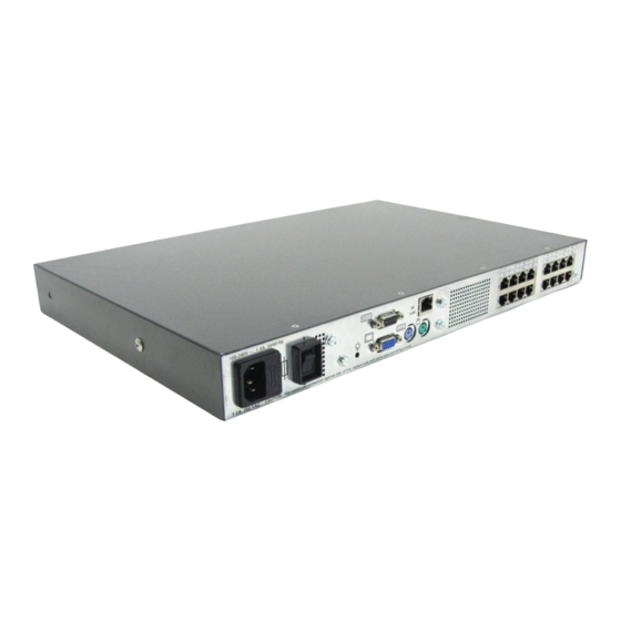
Component Identification In This Section Components............................7 Components Item Description Power cord connector Power switch Activity indicator light Serial port Monitor connector for local user Keyboard connector for local user Mouse connector for local user LAN connector Server connection ports... - Page 8 HP IP Console Switch User Guide Item Description HP IP Console Switch Network Keyboard connector Mouse connector Video connector...
-
Page 9: Installing The Hp Ip Console Switch
Installing the HP IP Console Switch In This Section Overview ............................9 Installation Checklist ........................9 Rack Mounting the HP IP Console Switch...................10 Overview You must install the HP IP Console Viewer before using the HP IP Console Switch. The HP IP Console Viewer enables you to view and control a server attached to the console switch system, configure and maintain the system, and prevent unauthorized access to the console switch through IP connection. -
Page 10: Required Items Not Included
HP IP Console Switch User Guide Power cords Rack mounting kit Serial download cable Documentation kit Firmware/software CD Required Items Not Included PS/2 Interface Adapter or USB Interface Adapter UTP CAT5 cable (CAT6 and CAT7 may also be used) Optional Items Expansion Module ("Installing the Expansion Module"... -
Page 11: Performing A Side-Mount Type A Installation
Installing the HP IP Console Switch NOTE: Before installing the HP IP Console Switch into the rack, connect the HP IP Console Switch to a power source, using the power cords provided, and power on the unit. An activity indicator light ("Components"... - Page 12 HP IP Console Switch User Guide 2. Attach the side-mounting brackets to the console switch using the four screws you removed. 3. Slide the side-mounting bracket tabs into the U locations on each side of the rack.
-
Page 13: Performing A Side-Mount Type B Installation
Installing the HP IP Console Switch 4. Secure the console switch to the rails using four self-tapping screws, two on each side. Performing a Side-Mount Type B Installation 1. Remove the four screws, two on each side, from the console switch. 2. -
Page 14: Performing A Standard-Mount Installation
HP IP Console Switch User Guide 3. Slide the side-mounting bracket tabs into the U locations on each side of the rack. 4. Install four cage nuts into the side-mounting bracket U locations. 5. Secure the console switch to the rails, using four M-6 screws, two on each side. - Page 15 Installing the HP IP Console Switch 2. Attach the 1U brackets to the console switch using the four screws you removed. 3. Install a cage nut behind each rear rail if they have not already been installed. 4. Slide the console switch into the rear of the 1U product.
-
Page 16: Performing A Cantilever-Mount Type A Installation
HP IP Console Switch User Guide 5. Secure the console switch to the rails using two M-6 screws, one on each side. Performing a Cantilever-Mount Type A Installation 1. Remove the four screws, two on each side, from the console switch. 2. -
Page 17: Performing A Cantilever-Mount Type B Installation
Installing the HP IP Console Switch 3. Install up to six clip nuts. 4. Secure the console switch to the rails, using the appropriate number of T-25 Torx screws. Performing a Cantilever-Mount Type B Installation 1. Remove the four screws, two on each side, from the console switch. - Page 18 HP IP Console Switch User Guide 2. Attach the 1U brackets to the console switch using the four screws you removed. 3. Install up to six cage nuts.
- Page 19 Installing the HP IP Console Switch 4. Secure the console switch to the rails using the appropriate number of M-6 screws.
-
Page 21: Installing The Expansion Module
Installing the Expansion Module In This Section Overview ............................21 Installation Checklist ........................21 Installing the Expansion Module Hardware .................21 Configuring the Expansion Module .....................24 Overview An optional Expansion Module can be added to the HP IP Console Switch system, increasing the total number of accessible servers. The Expansion Module ships with rack-mounting hardware for easy integration into the rack. -
Page 22: Performing A Side-Mount Installation
HP IP Console Switch User Guide Rail-mount Velcro-mount Performing a Side-Mount Installation 1. Slide the tabs on the side-mounting brackets into the rack frame. 2. Secure the Expansion Module to the rack frame, using one self-tapping screw for the bottom side-mounting bracket. -
Page 23: Performing A Rail-Mount Installation
Installing the Expansion Module Performing a Rail-Mount Installation 1. Remove the screws securing the side-mounting brackets to the Expansion Module. 2. Insert two cage nuts into the rack frame where the side-mounting bracket holes are located and secure the Expansion Module to the rack frame, using two M-6 screws. -
Page 24: Performing A Velcro-Mount Installation
HP IP Console Switch User Guide Performing a Velcro-Mount Installation 1. Determine the location for the Expansion Module. 2. Remove the protective strip from one side of the Velcro and attach that side to the Expansion Module. 3. Remove the protective strip from the other side of the Velcro and attach the Expansion Module to the rack frame. -
Page 25: Installing A Ps/2 Or Usb Interface Adapter
Installing a PS/2 or USB Interface Adapter In This Section Overview ............................25 Configuring the Interface Adapter....................25 Overview An Interface Adapter is required for the HP IP Console Switch system to function properly. However, it is not included in the HP IP Console Switch kit. An Interface Adapter connects UTP CAT5 cables to PS/2 or USB connections, establishing a KVM session to a server. - Page 26 HP IP Console Switch User Guide Item Description Server HP IP Console Switch USB Interface Adapter PS/2 Interface Adapter...
-
Page 27: Installing A Serial Interface Adapter
Installing a Serial Interface Adapter In This Section Overview ............................27 Installing the Serial Interface Adapter..................28 Optimal Performance Settings......................29 Serial Interface Adapter Modes ....................29 Serial Interface Adapter Pinouts....................34 Attaching the Power Supply to the Rack Using Velcro ...............34 Overview The HP Serial Interface Adapter is a serial-to-VGA converter, which permits VT100–capable devices to be viewed from the local ports of the HP IP Console Switch and HP KVM Server Console Switch, or by using the HP IP Console Viewer software. -
Page 28: Installing The Serial Interface Adapter
HP IP Console Switch User Guide Installing the Serial Interface Adapter Item Description Serial device (target server) Console Switch Additional serial interface adapter Serial interface adapter 9–pin connector Serial interface adapter RJ-45 connector Serial interface adapter power connector Power expander Power supply 1. -
Page 29: Optimal Performance Settings
Installing a Serial Interface Adapter If you are using a power expander (7), connect it to up to three additional serial interface adapters (3). NOTE: Do not power more than four serial interface adapters from a single power supply. 5. Repeat steps 2 through 4 to connect additional serial devices to the console switch. -
Page 30: History Mode
HP IP Console Switch User Guide Configuration Mode—This mode enables you to specify communication parameters, the appearance of serial data, and key combinations for specific actions and macros. History Mode The serial interface adapter maintains a buffer containing 240 lines minimum, or 10 screens, of output. -
Page 31: Configuration Mode
Installing a Serial Interface Adapter Configuration Mode Press the Ctrl+F8 keys to activate the Configuration menu. The Configuration menu contains menu items that enable you to configure your serial interface adapter. Communication Parameters The following communication parameters can be changed through the Configuration Mode: Baud Rate—This option enables you to specify the serial port communication speeds in bits per second (BPS). -
Page 32: Function Keys
HP IP Console Switch User Guide Normal Text—This options changes the normal text color of the screen. The currently selected color displays in the option line as it is changed. This color cannot be identical to the Bold Text or Background color. Bold Text—This options changes the bold text color of the screen. -
Page 33: Using Configuration Mode
Installing a Serial Interface Adapter Using Configuration Mode 1. Press the Ctrl+F8 keys. The Configuration screen appears. 2. Select a parameter to change. You can navigate the configuration screen using the up arrow and down arrow. 3. Modify the selected value using the left arrow and right arrow. 4. -
Page 34: Serial Interface Adapter Pinouts
HP IP Console Switch User Guide 8. When finished, press the Enter key to return to the Terminal screen. Serial Interface Adapter Pinouts The serial interface adapter is a DCE device. The following table lists the pinouts for the serial interface adapter. DB9F Pin Serial Interface Adapter Description Data Terminal Ready (DTR) - Page 35 Installing a Serial Interface Adapter 3. Remove the protective strip from the other side of the Velcro and attach the power supply to the rack frame.
-
Page 37: Cascading Console Switches
Cascading Console Switches In This Section Compatible Console Switch Models ....................37 Cascading a Compaq Server Console Switch with an HP IP Console Switch ......39 Cascading an HP KVM Server Console Switch with an HP IP Console Switch ......41 Compatible Console Switch Models Review the following information before cascading console switches with this product. -
Page 38: Hp Kvm Server Console Switch
HP IP Console Switch User Guide The following Compaq Server Console Switches can be integrated into the HP IP Console Switch system. Compatible Compaq Server Console Switch models include: 1 x 4 [PN: 400336 (-001)(-291)(-B31)] 1 x 8 [PN: 400337 (-001)(-291)(-B31)] 2 x 8 [PN: 400338 (-001)(-291)(-B31)] 2 x 8 48 VDC [PN: 400542 -B21] All Compaq Server Console Switches must be upgraded with SoftPaq firmware,... -
Page 39: Cascading A Compaq Server Console Switch With An Hp Ip Console Switch
Cascading Console Switches Cascading a Compaq Server Console Switch with an HP IP Console Switch 1. Mount the console switches in the rack. 2. Connect the local port KVM cable to the HP IP Console Switch. 3. Connect a UTP CAT5 cable to the server connection port ("Components" on page 7) on the HP IP Console Switch. -
Page 40: Example Of A Compaq Server Console Switch Cascade Configuration
HP IP Console Switch User Guide The following figure shows a Compaq Server Console Switch cascaded to an HP IP Console Switch. The top console switch is the main console switch, while the bottom console switch is the cascaded console switch. Example of a Compaq Server Console Switch Cascade Configuration... -
Page 41: Cascading An Hp Kvm Server Console Switch With An Hp Ip Console Switch
Cascading Console Switches Item Description Server KVM cable PS/2 Interface Adapter UTP CAT5 cable Cascaded Compaq Server Console Switch Local port Main HP IP Console Switch Cascading an HP KVM Server Console Switch with an HP IP Console Switch NOTE: To perform a firmware upgrade for a cascaded HP KVM Server Console Switch and all attached Interface Adapters, you must locally connect the keyboard, monitor, and mouse to the cascaded HP KVM Server Console Switch to access the local OSD. - Page 42 HP IP Console Switch User Guide 12. Power off the cascaded HP KVM Server Console Switch. 13. Power off the monitor. 14. Disconnect the local KVM cables from the cascaded HP KVM Server Console Switch. 15. Connect the local port KVM cable to main HP IP Console Switch. 16.
-
Page 43: Example Of An Hp Ip Console Switch Cascade Configuration
Cascading Console Switches CAUTION: Do not use Interface Adapters to cascade HP IP Console Switches with HP KVM Server Console Switches. If Interface Adapters are used to cascade these products, undesirable operations might occur. Example of an HP IP Console Switch Cascade Configuration... - Page 44 HP IP Console Switch User Guide Item Description Server PS/2 Interface Adapter or USB Interface Adapter* UTP CAT5 cable UTP CAT5 cable KVM cable Main HP IP Console Switch Local port Cascaded HP KVM Server Console Switch * not shown...
-
Page 45: Local Port Operation
Local Port Operation In This Section Overview ............................45 Soft Switching ..........................50 Using Basic OSD Navigation Keys....................51 Configuring the Setup Dialog Box ....................52 Managing Server Tasks Using the OSD..................74 Overview The HP IP Console Switch system has one local port on the rear panel ("Components"... -
Page 46: Viewing And Selecting Ports And Servers
HP IP Console Switch User Guide NOTE: You can also press the Ctrl key twice within one second to launch the OSD. You can use this key sequence in any place you see Print Scrn. Viewing and Selecting Ports and Servers You can view servers by name, port, or by the unique EID embedded in each Interface Adapter. - Page 47 Local Port Operation The Port column indicates the port to which a server is connected. For example, in the following screen shot, the first number represents the port number of the first console switch and the second number represents the port number of the cascaded console switch port to which the server is connected.
- Page 48 HP IP Console Switch User Guide Port number Port number Server Description of the first of the Status Icon console cascaded displayed switch console switch The server is connected to the first console switch and the Interface Adapter is not connected or the server is powered off.
-
Page 49: Selecting Servers
Local Port Operation Selecting Servers From the Main dialog box ("Accessing the Main Dialog Box" on page 45), users can select specific servers. When a new server is selected, the console switch reconfigures the KVM to the setting for the selected server. Double-click the server Name, EID, or Port number. -
Page 50: Soft Switching
HP IP Console Switch User Guide Soft Switching Soft switching is the ability to switch servers using a hotkey sequence. You can soft switch to a server by pressing the Print Scrn key and entering the first few characters of its name or number. If you have set a Screen Delay Time and you press the key sequences before that time has elapsed, the OSD does not display. -
Page 51: Using Basic Osd Navigation Keys
Local Port Operation Using Basic OSD Navigation Keys Keystroke Description Print Scrn Opens the OSD Main dialog box. Press the Print Scrn key twice to send the Print Scrn keystroke to the currently selected device. Opens the Help screen for the current dialog box. Closes the current dialog box without saving changes and returns to the previous dialog box. -
Page 52: Configuring The Setup Dialog Box
HP IP Console Switch User Guide Keystroke Description Deletes from current selection to all lines below it when editing a scan list. Shift, Delete Adds numbers from the keyboard or keypad. Numbers Caps Lock Disables the user. (Use the Shift key to change case.) Configuring the Setup Dialog Box You can configure the HP IP Console Switch and manage routine tasks for your servers from the Setup dialog box ("Accessing the Setup Dialog Box"... -
Page 53: Managing Routine Tasks For Servers
Local Port Operation Managing Routine Tasks for Servers Button Function Menu Changes the server listing between numerically by port or EID number and alphabetically by name. Changes the delay time before the Main dialog box displays after pressing the Print Scrn key. - Page 54 HP IP Console Switch User Guide Accessing the Menu Dialog Box From the Main dialog box ("Accessing the Main Dialog Box" on page 45), click Setup>Menu. The Menu dialog box is displayed. Selecting the Display Order of Servers 1. From the Menu dialog box ("Accessing the Menu Dialog Box" on page 54), select Name to display servers alphabetically by name.
-
Page 55: Controlling The Status Flag
Local Port Operation Setting a Screen Delay Time Setting a time to delay the display of the OSD enables you to complete a soft switch ("Soft Switching" on page 50) without displaying the OSD. It is strongly recommended to leave the number of seconds (0-9) the OSD is delayed to the default (0). -
Page 56: Accessing The Flag Dialog Box
HP IP Console Switch User Guide Accessing the Flag Dialog Box From the Main dialog box ("Accessing the Main Dialog Box" on page 45), click Setup>Flag. The Flag dialog box is displayed. Displaying the Status Flag 1. From the Flag dialog box ("Accessing the Flag Dialog Box" on page 56), select Name or EID to determine what information is displayed. -
Page 57: Broadcasting To Servers
Local Port Operation 6. Click OK to save settings. -or- Click X to exit, or press the Esc key to exit without saving settings. NOTE: Changes made to the position flag are not saved until you click OK in the Flag dialog box ("Accessing the Flag Dialog Box" on page 56). -
Page 58: Broadcasting Selected Servers
HP IP Console Switch User Guide Broadcasting Selected Servers 1. From the Broadcast dialog box ("Accessing the Broadcast Dialog Box" on page 57), select the keyboard and mouse checkboxes for the servers that are to receive the broadcast commands. -or- Press the Up or Down Arrow keys to move the cursor to the target server. -
Page 59: Setting Up A Scan Pattern
Local Port Operation Activating the Broadcast Dialog Box To activate or deactivate broadcasting, from the Commands dialog box ("Accessing the Commands Dialog Box" on page 75), select or deselect Broadcast Enable. Setting Up a Scan Pattern In Scan mode ("Activating Scan Mode" on page 61), the HP IP Console Switch automatically scans port to port (server to server).You can select up to 16 servers from a list of all servers attached to the HP IP Console Switch. -
Page 60: Removing Servers From The Scan List
HP IP Console Switch User Guide Adding Servers to the Scan List 1. From the Scan dialog box ("Activating Scan Mode" on page 61), select the checkbox beside each server to be added to the scan list. -or- Double-click a server name or port. -or- Press the Alt key plus the number of the server you want to scan. -
Page 61: Setting Local Console Switch Security
Local Port Operation Activating Scan Mode 1. From the Commands dialog box ("Accessing the Commands Dialog Box" on page 75), select Scan Enable. 2. Click X to close the Commands dialog box. NOTE: The scanning begins as soon as you click Scan. Deactivating Scan Mode If the OSD is open, select a server. - Page 62 HP IP Console Switch User Guide Accessing the Security Dialog Box From the Main dialog box ("Accessing the Main Dialog Box" on page 45), click Setup>Security. The Security dialog box is displayed. Changing the Password 1. From the Security dialog box ("Accessing the Security Dialog Box" on page 62), click the New field and press the Enter key if the OSD is not open, or double-click the New field.
- Page 63 Local Port Operation 3. Enter the number of minutes for Time Delay (from 1 to 99) to delay activation of password protection and the screen saver feature. 4. For Mode, select Energy if your monitor is Energy Star® compliant. Otherwise, select Screen. 5.
-
Page 64: Exiting Screen Saver Mode
HP IP Console Switch User Guide Exiting Screen Saver Mode To exit the Screen Saver mode, press any key or move the mouse. The Main dialog box ("Accessing the Main Dialog Box" on page 45) is displayed. Deactivating the Screen Saver 1. -
Page 65: Preemption Mode
Local Port Operation Preemption Mode Preemption provides a means for users with sufficient access level to take control of a server from another (remote or local) user with lesser or equal access level. Depending on the access level of the user issuing the preemption request and that of the user being preempted, the preemption request can be rejected. - Page 66 HP IP Console Switch User Guide Accessing Preempt Dialog Box From the Main dialog box ("Accessing the Main Dialog Box" on page 45), click Setup>Preempt. The Preempt dialog box appears. Assigning a Preempt Timeout In the Preempt dialog box ("Accessing Preempt Dialog Box" on page 66), enter a value in the Timeout Seconds field and click OK.
- Page 67 Local Port Operation When you attempt to preempt another user or Admin, a message appears on your screen, and a Preempt Warning appears on the screen of the user or Admin. These dialogs appear for the time assigned in the Timeout Seconds field set through either the local OSD or the HP IP Console Viewer.
-
Page 68: Changing The Usb Keyboard Language
HP IP Console Switch User Guide Changing the USB Keyboard Language You can select the language for all USB Interface Adapters connected to the console switch. Accessing the Keyboard Dialog Box From the Main dialog box ("Accessing the Main Dialog Box" on page 45), click Setup>Keyboard. -
Page 69: Assigning Device Types
Local Port Operation Selecting the Keyboard Language 1. From the Keyboard dialog box ("Accessing the Keyboard Dialog Box" on page 68), select the keyboard country code. A Keyboard Warning appears. 2. Click OK. Assigning Device Types While the console switches automatically discovers cascaded Compaq Server Console Switches attached to your unit, you must specify the number of ports on the cascade Compaq Server Console Switch through the Devices dialog box. -
Page 70: Modifying Device Types
HP IP Console Switch User Guide When the HP IP Console Switch discovers a cascaded HP KVM Server Console Switch the port numbering changes automatically to accommodate each server under that console switch. For example, if the console switch is connected to port 02, the switch port is listed as 02, and each server under it is numbered sequentially 02-01, 02-02, and so on. - Page 71 Local Port Operation 2. Click Modify. The Device Modify dialog box is displayed. 3. Select the number of ports supported by the cascaded Compaq Server Console Switch. 4. Click OK. 5. Repeat steps 2 through 4 for each port the user wants to assign a device type. 6.
- Page 72 HP IP Console Switch User Guide Assigning Names to Servers 1. From the Names dialog box ("Accessing the Names Dialog Box" on page 73), select the name or port number and click Modify. The Name Modify dialog box is displayed. 2.
-
Page 73: Assigning Server Names
Local Port Operation Assigning Server Names Use the Names dialog box ("Accessing the Names Dialog Box" on page 73) to identify individual servers or serial devices by name rather than by port number. The Names list is always sorted by port order, and the names are stored in the Interface Adapter. -
Page 74: Managing Server Tasks Using The Osd
HP IP Console Switch User Guide Managing Server Tasks Using the OSD You can manage the HP IP Console Switch system from the Commands dialog box ("Accessing the Commands Dialog Box" on page 75) with the OSD, including engaging Scan mode ("Activating Scan Mode" on page 61) and Broadcast mode ("Activating the Broadcast Dialog Box"... -
Page 75: Accessing The Commands Dialog Box
Local Port Operation Accessing the Commands Dialog Box From the Main dialog box ("Accessing the Main Dialog Box" on page 45), click Commands. The Commands dialog box appears. Viewing and Disconnecting User Connections You can view and disconnect remote network users through the User Status dialog box ("Viewing Current User Connections"... - Page 76 HP IP Console Switch User Guide Viewing Current User Connections From the Main dialog box ("Accessing the Main Dialog Box" on page 45), click Commands>User Status. The User Status dialog box appears. Disconnecting a User 1. From the Main dialog box ("Accessing the Main Dialog Box" on page 45), click Commands>User Status.
-
Page 77: Running System Diagnostics
Local Port Operation 2. Click the letter of the user to be disconnected. The Disconnect dialog box appears. 3. Click OK to disconnect the user and return to the User Status dialog box. -or- Click X to exit, or press the Esc key to exit the dialog box without disconnecting a user. -
Page 78: Hp Ip Console Switch User Guide
HP IP Console Switch User Guide Test Description Validates the current firmware images stored in the system FLASH by Firmware CRCs comparing a CRC value on each image and comparing those results to the expected values. Verifies the intra-board communication subsystems are accessible and Comm Interfaces functional by querying the communications controller and performing basic register level tests. - Page 79 Local Port Operation Activating Run Diagnostics 1. From the Main dialog box ("Accessing the Main Dialog Box" on page 45), click Commands>Run Diagnostics. A warning message appears, indicating that all users will be disconnected. 2. Click OK to begin. All users are disconnected, and the Diagnostics dialog box appears.
- Page 80 HP IP Console Switch User Guide Click X or press the Esc key to exit the dialog box without running a diagnostic test. 3. As each test is finished, a pass or fail symbol appears. A passed test is indicated with a green circle, and a red X indicates a failed test.
-
Page 81: Resetting The Ps/2 Device
Local Port Operation 5. (Optional) If you have any suspect Interface Adapters, you can click Display. The Suspect Interface Adapter dialog box appears. Resetting the PS/2 Device NOTE: The reset PS/2 device function is only for cascaded console switches. If your PS/2 device locks up, you can re-establish operation of these peripherals by issuing a device reset. -
Page 82: Displaying Version Information
HP IP Console Switch User Guide 2. Click Device Reset. A warning appears. Displaying Version Information The Display Versions dialog box ("Accessing the Version Dialog Box" on page 82) enables you to view the HP IP Console Switch versions, as well as keyboard and mouse information for the currently selected server. - Page 83 Local Port Operation 1. From the Main dialog box ("Accessing the Main Dialog Box" on page 45), click Commands>Display Versions. The Version dialog box appears. The top half of the box lists the subsystem versions in the HP IP Console Switch. 2.
- Page 84 HP IP Console Switch User Guide 3. Click IA to access the IA Selection dialog box to view individual Interface Adapter cable version information. The IA Selection dialog box appears.
- Page 85 Local Port Operation 4. To view the selected Interface Adapter cable, click Version. The IA Version dialog box appears.
-
Page 86: Resetting The Ps/2 Interface Adapter
HP IP Console Switch User Guide 5. Click X to exit. Resetting the PS/2 Interface Adapter NOTE: The reset PS/2 device function is only for cascaded console switches. Occasionally, when cascading to a legacy console switch, a PS/2 Interface Adapter can drop out of the cascade configuration. In the IA Version dialog box of a PS/2 Interface Adapter, you can reset that Interface Adapter. -
Page 87: Upgrading The Interface Adapter Firmware
Local Port Operation 3. In the IA Version dialog box for the PS/2 interface Adapter, click Reset. A Reset IA warning appears and the PS/2 Interface Adapter is reset. Upgrading the Interface Adapter Firmware The Interface Adapter firmware can be loaded individually ("Loading the Interface Adapter Firmware Individually"... - Page 88 HP IP Console Switch User Guide 2. Click IA. The IA Selection dialog box is displayed. 3. Select the individual Interface Adapter, and click Version. The IA Version dialog box is displayed. 4. Click Load Firmware. Upgrading the Interface Adapter Firmware Simultaneously 1.
- Page 89 Local Port Operation 2. Select PS/2, USB, or Serial then click Upgrade. The IA Upgrade dialog box is displayed. 3. Click OK to save settings. 4. Press the Esc key to return to the Main dialog box ("Accessing the Main Dialog Box"...
-
Page 91: Network Settings
Network Settings In This Section Setting Up A Network ........................91 Establishing LAN Connections ....................91 Configuring the HP IP Console Switch Hardware ...............91 Mouse Drivers ..........................94 Setting Up A Network The HP IP Console Switch system uses IP address to uniquely identify the console switches and computers running the HP IP Console Viewer. - Page 92 HP IP Console Switch User Guide 3. Configure the terminal emulation software for the server, such as Hyperterminal or Minicom ("Configuring Minicom" on page 93). 4. Plug the supplied power cord into the power cord connector ("Components" on page 7) on the HP IP Console Switch and then into a valid power source, if not already connected.
-
Page 93: Configuring Minicom
Network Settings 9. Select Option 3 through 6 from the Terminal Applications menu to finish configuring the console switch for an IP Address, Netmask, Default Gateway, and DNS. When this configuration is complete, enter 0 to return to the IPViewer HyperTerminal menu. Configuring Minicom NOTE: The example below is uses Red Hat 3.0. -
Page 94: Mouse Drivers
HP IP Console Switch User Guide 3. Select Option A (Serial Device). Manually change the device type from "dev/modem" to "/dev/ttyS0" and press the Enter key. 4. Select Option E (Bps/Par/Bits). The Comm Parameters menu appears. 5. Select E (Speed 9600 Bps), and press the Enter key. The designation 9600 8N1 appears next to Option E. -
Page 95: Upgrading The Firmware Using Tftp
Upgrading the Firmware Using TFTP In This Section Overview ............................95 Upgrading the HP IP Console Switch Firmware................97 Overview The HP IP Console Switch upgrade feature enables you to upgrade the HP IP Console Switch with the latest available firmware through either the serial cable connector or HP IP Console Viewer. - Page 96 HP IP Console Switch User Guide NOTE: By default, TFTP executes in secure mode and only provides readable files under the /tftpboot directory. Other directories can be specified through the /etc/xinetd.d/tftp files. In secure mode, TFTP expects the file to be relative to the/tftpboot directory. To enable TFTP for Linux operating systems (GNOME): 1.
-
Page 97: Upgrading The Hp Ip Console Switch Firmware
Upgrading the Firmware Using TFTP 3. Copy the firmware file to /tftpboot. 4. Cd to /tmp. 5. From the shell prompt, enter tftp localhost (or name of local system). 6. Download the file by entering the following command: get/tftpboot/filename 7. Enter quit. 8. - Page 98 HP IP Console Switch User Guide 4. Plug the supplied power cord into the power cord connector ("Components" on page 7) on the HP IP Console Switch and then into a valid power source, if not already connected. 5. Power on the HP IP Console Switch, if not already powered on. The activity indicator light ("Components"...
-
Page 99: Upgrading The Hp Ip Console Switch Firmware Through The Ip Console Viewer
Upgrading the Firmware Using TFTP CAUTION: Do not cycle power to the HP IP Console Switch during this process. A loss of power might render the HP IP Console Switch inoperable and require that the unit be returned to the factory for repair. -
Page 101: Troubleshooting
Troubleshooting In This Section When a Serial Interface Adapter Stops Responding..............101 When the Activity Light Indicator is Not On ................102 When the Cable Connections Are Not Correct................102 When the Cascaded Console Switch Configurations Are Not Correct ........102 When the Console Switch Does Not Have the Correct Firmware..........103 When the Console Switch is Not Working Properly ..............103... -
Page 102: When The Activity Light Indicator Is Not On
HP IP Console Switch User Guide When the Activity Light Indicator is Not On 1. Be sure that the HP IP Console Switch is powered on and that the power source is valid. 2. Be sure that the cable connections are correct. When the Cable Connections Are Not Correct 1. -
Page 103: When The Console Switch Does Not Have The Correct Firmware
Troubleshooting 2. Be sure that the cascade configurations ("Cascading Console Switches" on page 37) are correct. 3. Be sure that the cascaded console switches are powered on. IMPORTANT: While upgrading the firmware, do not power off the HP IP Console Switch or attempt any operations. 4. -
Page 104: When The Console Switch Serial Port Password Is Lost
HP IP Console Switch User Guide a. Power on any cascaded console switches. b. Power on the HP IP Console Switch. The activity indicator light powers c. Power on the monitor. d. Power up the server. When the Console Switch Serial Port Password is Lost Ultimate responsibility for data security must be enforced by you. -
Page 105: When The Local User Cannot View The Osd Flag
Troubleshooting 2. Be sure that the cable connections are correct. 3. Be sure that the monitor is valid. When the Local User Cannot View the OSD Flag Preview the preferences selected in the OSD to determine if the local port display has been disabled or set to time out. -
Page 106: When The Osd Is Distorted Or Not Readable
HP IP Console Switch User Guide When the OSD is Distorted or Not Readable Be sure that the monitor to which the target server is set supports the refresh rate. When the OSD is Inaccessible Press the Ctrl key twice. When RILOE and iLO are not Working Correctly with the HP IP Console Switch The HP IP Console Switch firmware must be version 3.0.0 or later. -
Page 107: When The System Does Not Recognize The Cascaded Console Switches
Troubleshooting When the System Does Not Recognize the Cascaded Console Switches IMPORTANT: While upgrading the firmware, do not power off the HP IP Console Switch or attempt any operations. Be sure that all of the console switches are upgraded with the latest firmware ("Upgrading the HP IP Console Switch Firmware"... -
Page 109: Frequently Asked Questions
Frequently Asked Questions In This Section Are the Expansion Module Ports Hot-Pluggable?..............109 Are the Interface Adapters Hot-Pluggable?................109 Are the Keyboard, Monitor, and Mouse Connections on the Console Switch Hot-Pluggable? .110 Are the Server Connections on the Console Switch Hot-Pluggable? .........110 Can the Console Switch Be Mounted in a Round-Hole Rack? ..........110 Can the Console Switch Be Side-Mounted in a Round-Hole Rack? -
Page 110: Are The Keyboard, Monitor, And Mouse Connections On The Console Switch Hot-Pluggable
HP IP Console Switch User Guide Are the Keyboard, Monitor, and Mouse Connections on the Console Switch Hot-Pluggable? Yes. Are the Server Connections on the Console Switch Hot-Pluggable? Yes. Can the Console Switch Be Mounted in a Round-Hole Rack? Yes, the HP IP Console Switch can be mounted in a round-hole rack using the standard-mount installation. -
Page 111: Does The Customer Have The Correct Configurations
Frequently Asked Questions 1. Be sure that you have the latest console switch firmware version ("Displaying Version Information" on page 82) and Interface Adapter firmware version ("Displaying Version Information" on page 82). 2. Upgrade the console switch firmware ("Upgrading the HP IP Console Switch Firmware"... -
Page 112: How Do I Cascade Console Switches
HP IP Console Switch User Guide NOTE: You can also press the Ctrl key twice within one second to launch the OSD. You can use this key sequence in any place you see Print Scrn. How Do I Cascade Console Switches? Refer to "Cascading Console Switches (on page 37)."... -
Page 113: How Do I Know Which Port My Cascaded Console Switch Is Connected To
Frequently Asked Questions How Do I Know Which Port My Cascaded Console Switch is Connected To? Refer to "Viewing and Selecting Ports and Servers (on page 46, "Viewing the Port Column" on page 46)." How Do I Locally Connect a Cascaded Console Switch? 1. -
Page 114: How Do I Use The Run Diagnostics Feature
HP IP Console Switch User Guide 2. Click OK to save settings. To immediately activate the screen saver, press the Print Scrn key, and then press the Pause key. This command only works when the user is connected to a server. -
Page 115: Why Can Remote Hp Ip Console Switch Users Not Access Servers Attached To A Cascaded Hp Kvm Server Console Switch
Frequently Asked Questions Why Can Remote HP IP Console Switch Users Not Access Servers Attached to a Cascaded HP KVM Server Console Switch? In order for remote HP IP Console Switch users to access servers attached to a cascaded HP KVM Server Console Switch, the HP KVM Server Console Switch must be in Free Mode or have the screen saver enabled. -
Page 117: Regulatory Compliance Notices
Regulatory Compliance Notices In This Section Regulatory Compliance Identification Numbers ................117 Federal Communications Commission Notice ................118 Declaration of Conformity for Products Marked with the FCC Logo, United States Only ..119 Modifications..........................120 Cables ............................120 Canadian Notice (Avis Canadien) ....................120 European Union Notice ......................121 Japanese Notice ..........................121... -
Page 118: Federal Communications Commission Notice
HP IP Console Switch User Guide Federal Communications Commission Notice Part 15 of the Federal Communications Commission (FCC) Rules and Regulations has established Radio Frequency (RF) emission limits to provide an interference-free radio frequency spectrum. Many electronic devices, including computers, generate RF energy incidental to their intended function and are, therefore, covered by these rules. -
Page 119: Class B Equipment
(2) this device must accept any interference received, including interference that may cause undesired operation. For questions regarding this product, contact us by mail or telephone: Hewlett-Packard Company P. O. Box 692000, Mail Stop 530113 Houston, Texas 77269-2000 1-800-652-6672 (For continuous quality improvement, calls may be recorded or monitored.) -
Page 120: Modifications
Modifications The FCC requires the user to be notified that any changes or modifications made to this device that are not expressly approved by Hewlett-Packard Company may void the user’s authority to operate the equipment. Cables Connections to this device must be made with shielded cables with metallic RFI/EMI connector hoods in order to maintain compliance with FCC Rules and Regulations. -
Page 121: European Union Notice
Regulatory Compliance Notices European Union Notice Products bearing the CE marking comply with the EMC Directive (89/336/EEC) and the Low Voltage Directive (73/23/EEC) issued by the Commission of the European Community and, if this product has telecommunication functionality, the R&TTE Directive (1999/5/EC). Compliance with these directives implies conformity to the following European Norms (in parentheses are the equivalent international standards and regulations): EN 55022 (CISPR 22)—Electromagnetic Interference... -
Page 122: Bsmi Notice
HP IP Console Switch User Guide BSMI Notice Korean Notices Class A Equipment Class B Equipment... -
Page 123: Acronyms And Abbreviations
Acronyms and Abbreviations central processing unit cyclic redundant checks DHCP Dynamic Host Configuration Protocol electronic identification number engineer problem resolution Interface Adapter Internet Protocol keyboard, video, and mouse... - Page 124 HP IP Console Switch User Guide on-screen display Red Hat Package Manager Transmission Control Protocol TFTP Trivial File Transfer Protocol universal serial bus unshielded twisted pair voltage direct-current video graphics array...
- Page 125 cables, VGA 107 Index cabling 102, 107, 114 Canadian Notice 120 cascaded console switch configurations 40, 43, 104, 112, 113, 115 cascading console switches 37, 39, 41, 112, 113, 115 changing the display behavior 53 accessing servers 115 changing the password 62 accessing the Broadcast dialog box 57 changing the USB keyboard language 68 accessing the Commands dialog box 75...
- Page 126 HP IP Console Switch User Guide keyboard language 112 kit contents, Expansion Module 21 enabling TFTP 95 Korean notices 122 establishing LAN connections 91 European Union notice 121 exiting Screen Saver mode 64 Expansion Module 21, 22, 23, 24, 104, 109 languages, keyboard 112 Expansion Module configuration 109 Linux 95, 96...
- Page 127 Index power cord connector 7 Setup menu 52, 53 powering down 110 side-mount 22 powering on problems 103 soft switching 50 preemption mode 65 problem diagnosis 101 TFTP 95 troubleshooting 101 rack mounting configurations 10, 110 rack mounting hardware 110 rail-mount 23 upgrading cascade console switch regulatory compliance notices 117...