
Prediction of Power Generation Performance of Wound Rotor Synchronous Generator Using Nonlinear Magnetic Equivalent Circuit Method


Abstract
:1. Introduction
2. Proposal Nonlinear Magnetic Equivalent Circuit Method
2.1. Configuration of Stator and Rotor Nonlinear MEC
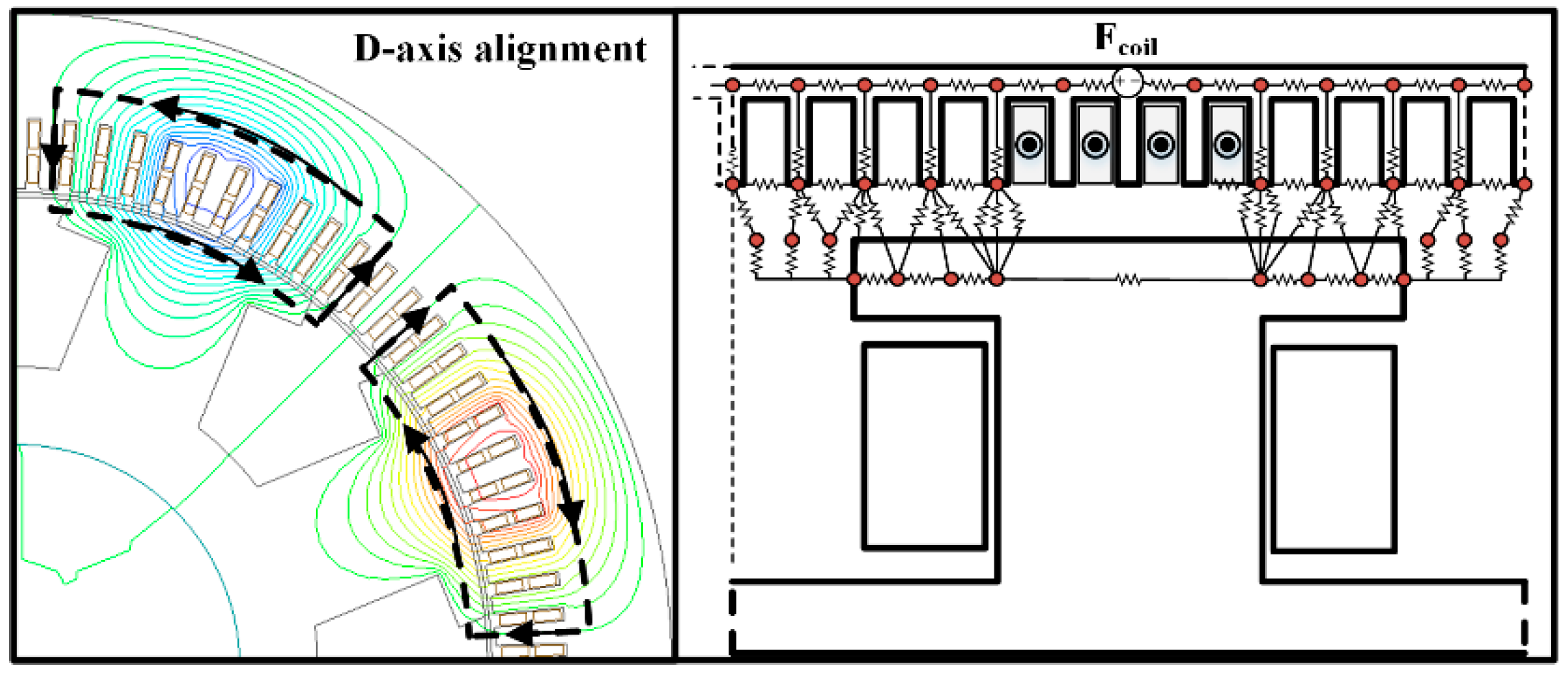
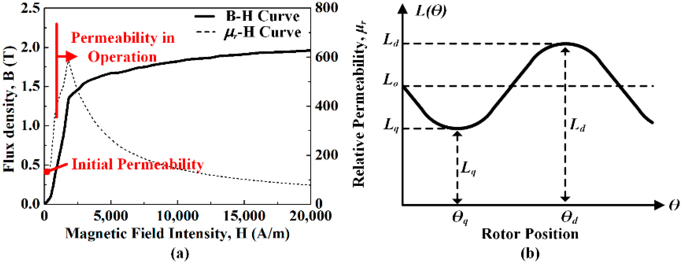
2.2. Configuration of Axis MEC
3. Calculations of Electrical Parameters
3.1. Resistance
3.2. Inductance
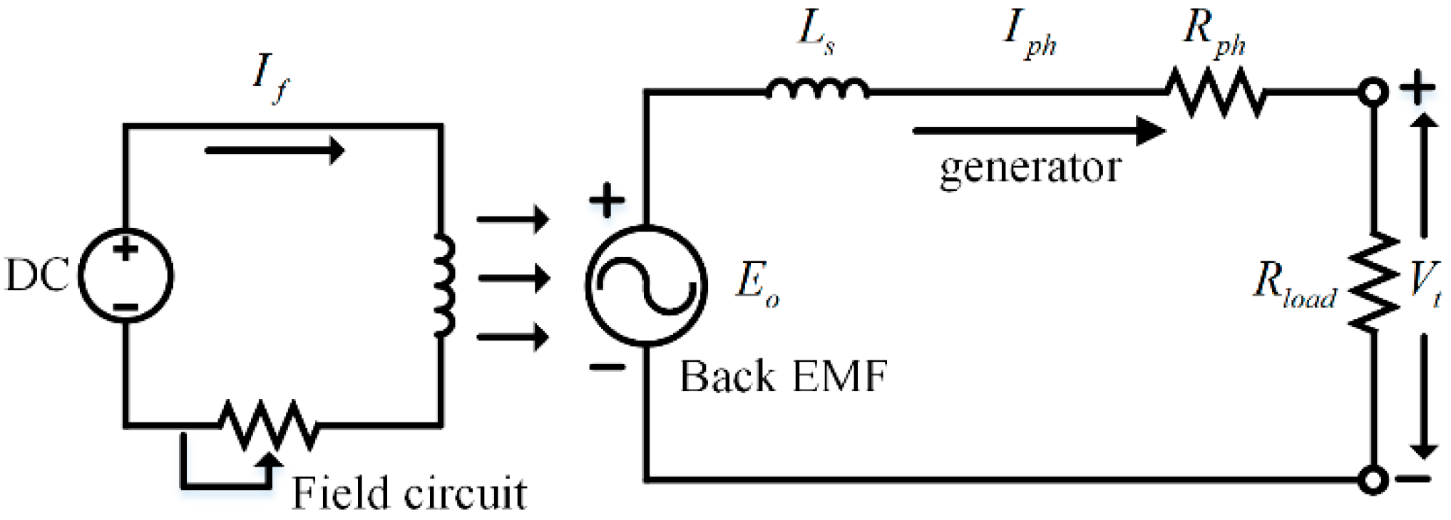
3.3. Back EMF
3.4. Generating Characteristic Analysis
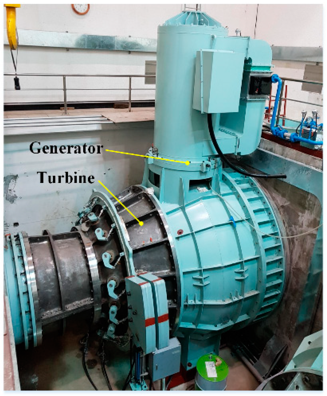
4. Verification of MEC Analysis
5. Conclusions
Author Contributions
Funding
Institutional Review Board Statement
Informed Consent Statement
Data Availability Statement
Conflicts of Interest
References
- Nuzzo, S.; Degano, M.; Galea, M.; Gerada, C.; Gerada, D.; Brown, N. Improved Damper Cage Design for Salient-Pole Synchronous Generators. IEEE Trans. Ind. Electron. 2017, 64, 1958–1970. [Google Scholar] [CrossRef] [Green Version]
- Griffo, A.; Drury, D.; Sawata., T.; Mellor, P.-H. Sensorless Starting of a Wound-Field Synchronous Starter/Generator for Aerospace Applications. IEEE Trans. Ind. Electron. 2012, 59, 3579–3587. [Google Scholar] [CrossRef]
- Wang, Q.; Zou, J.; Zhao, M. Analysis and Computer-Aided Simulation of Cogging Force Characteristic of a Linear Electromagnetic Launcher with Tubular Transverse Flux Machine. IEEE Trans. Plasma. Sci. 2011, 39, 157–161. [Google Scholar] [CrossRef]
- Cheng, M.; Chau, K.-T.; Chan, C.-C.; Zhou, E.; Huang, X. Nonlinear Varying-Network Magnetic Circuit Analysis for Doubly Salient Permanent-Magnet Motors. IEEE Trans. Magn. 2000, 36, 339–348. [Google Scholar] [CrossRef]
- Bash, M.; Williams, J.; Pekarek, S. Incorporating Motion in Mesh-Based Magnetic Equivalent Circuits. IEEE Trans. Energy Convers. 2010, 25, 329–338. [Google Scholar] [CrossRef]
- Wang, R.; Bash, M.; Pekarek, S.; Larson, A.; Maaren, R.-V. A Voltage Input-Based Magnetic Equivalent Circuit Model for Wound Rotor Synchronous Machines. In Proceedings of the 2013 International Electric Machines & Drives Conference, Chicago, IL, USA, 12–15 May 2013. [Google Scholar]
- Bash, M.; Pekarek, S. Analysis and Validation of a Population-Based Design of a Wound-Rotor Synchronous Machine. IEEE Trans. Energy Convers. 2012, 27, 603–614. [Google Scholar] [CrossRef]
- Bash, M.; Pekarek, S. Modeling of salient-pole wound-rotor synchronous machines for population-based design. IEEE Trans. Energy Convers. 2011, 26, 381–392. [Google Scholar] [CrossRef]
- Derbas, H.-W.; Williams, J.-M.; Koenig, A.-C.; Pekarek, S. A Comparison of Nodal- and Mesh-Based Magnetic Equivalent Circuit Models. IEEE Trans. Energy Convers. 2009, 24, 388–396. [Google Scholar] [CrossRef] [Green Version]
- Wang, R.; Pekarek, S.; Bash, M.; Larson, A.; Maren, R. Incorporating Dynamics in a Mesh-Based Magnetic Equivalent Circuit Model of Synchronous Machines. IEEE Trans. Energy Convers. 2015, 30, 821–832. [Google Scholar] [CrossRef]
- Ostovic, V. A Novel Method of Evaluation of Transient States in Saturated Electrical Machines. IEEE Trans. Ind. Appl. 1989, 25, 96–100. [Google Scholar] [CrossRef]
- Yao, L. Magnetic Field Modeling of Machine and Multiple Machine Systems Using Dynamic Reluctance Mesh Modeling. Ph.D. Thesis, University of Nottingham, Nottingham, UK, 2006. [Google Scholar]
- Lee, J.-J.; Lee, J.; Kim, K.-S. Design of a WFSM for Electric Veicle Based on a Nonlinear Magnetic Equivalent Circuit. IEEE Trans. Appl. Supercon. 2018, 28, 5206304. [Google Scholar] [CrossRef]
- Lipo, T.-A. Introduction to AC Machine Design, 2nd ed.; Wisconsin Power Electronics Research Center: Madison, WI, USA, 2004; pp. 79–124. [Google Scholar]
- Shin, K.-H.; Jung, K.-H.; Cho, H.-W.; Choi, J.-Y. Analytical Modeling and Experimental Verification for Electromagnetic Analysis of Tubular Linear Synchronous Machines with Axially Magnetized Permanent Magnets and Flux-Passing Iron Poles. IEEE Trans. Magn. 2018, 54, 8204006. [Google Scholar] [CrossRef]


| Parameter | Value | Unit |
|---|---|---|
| No. of poles/slots | 8/96 | - |
| Stator outer/inner diameter | 1045/765 | mm |
| Rotor outer/inner diameter | 751/356 | mm |
| Depth | 800 | mm |
| Output power | 900 | kW |
| Rated speed | 900 | RPM |
| Terminal voltage (no-load) | 3300 | V |
| Rated current | 185 | A |
| Slot pitch | 11 | - |
| Stator core | 50PN400 | - |
| Rotor core | SS400 | - |
| Parameter | FEM | MEC | Measured |
|---|---|---|---|
| d–axis inductance | 18.95 mH | 17.4 mH | - |
| q–axis inductance | 14.47 mH | 12.3 mH | - |
| Back EMF | 2238 V | 2207 V | 2310 V |
| Inductance | 16.5 mH | 14.8 mH | - |
| Resistance | - | 0.041 ohm | 0.039 ohm |
Publisher’s Note: MDPI stays neutral with regard to jurisdictional claims in published maps and institutional affiliations. |
© 2021 by the authors. Licensee MDPI, Basel, Switzerland. This article is an open access article distributed under the terms and conditions of the Creative Commons Attribution (CC BY) license (https://creativecommons.org/licenses/by/4.0/).
Share and Cite
Shin, H.-S.; Kwon, D.-Y.; Woo, J.-H.; Lee, H.-K.; Choi, J.-Y. Prediction of Power Generation Performance of Wound Rotor Synchronous Generator Using Nonlinear Magnetic Equivalent Circuit Method. Energies 2021, 14, 6190. https://doi.org/10.3390/en14196190
Shin H-S, Kwon D-Y, Woo J-H, Lee H-K, Choi J-Y. Prediction of Power Generation Performance of Wound Rotor Synchronous Generator Using Nonlinear Magnetic Equivalent Circuit Method. Energies. 2021; 14(19):6190. https://doi.org/10.3390/en14196190
Chicago/Turabian StyleShin, Hyo-Seob, Do-Yun Kwon, Jong-Hyeon Woo, Hoon-Ki Lee, and Jang-Yong Choi. 2021. "Prediction of Power Generation Performance of Wound Rotor Synchronous Generator Using Nonlinear Magnetic Equivalent Circuit Method" Energies 14, no. 19: 6190. https://doi.org/10.3390/en14196190