
Mutual Coupling Compensation Techniques Used for Distance Protection of Parallel Lines †


1
Department of Electrical and Electronic, Munster Technological University, Bishopstown, T12 P928 Cork, Ireland
2
Electricity Supply Board, Rosbrien Rd, V94 A5D2 Limerick, Ireland
*
Author to whom correspondence should be addressed.
†
This paper expands on a version of our paper published in 2020 55th International Universities Power Engineering Conference (UPEC), Torino, Italy, 1–4 September 2020, pp. 1–6.
Energies 2021, 14(7), 1982; https://doi.org/10.3390/en14071982
Submission received: 13 February 2021
/
Revised: 23 March 2021
/
Accepted: 1 April 2021
/
Published: 2 April 2021
(This article belongs to the Special Issue Verifying the Targets—Selected Papers from the 55th International Universities Power Engineering Conference (UPEC 2020))
Abstract
:When a distance relay protects a transmission line located on a dual circuit tower, a coupling effect will occur between the two circuits. Transposition of the circuits can reduce the mutual impedances, but this does not cater to the zero-sequence mutual coupling impedance during earth faults. As a result, the impedance measured by a distance relay under phase-to-earth fault conditions in these circumstances will not represent the correct impedance to the fault point unless these effects are taken into account. On multi-circuit lines, primarily if they operate in parallel, a zero-sequence mutual coupling should be considered when calculating settings for distance protection function. A 220 kV parallel line sharing the same tower was analysed using DigSilent Power Factory in the simulations. Phase-to-earth faults in different configurations were analysed on this system, and the reach of the protection relay was then estimated for operation. The results confirm how a protection relay can overreach and underreach in a distance protection scheme due to the influence of mutual coupling.
1. Introduction
Mutual coupling of overhead lines occurs when two or more circuits are in close proximity in the same corridor. Parallel circuits are widely utilised in transmission networks to improve the reliability and security of the system. Today, environmental conditions and planning restrictions are forcing utilities to install more and more parallel lines. This configuration imposes a unique problem for the associated line protection relays [1]. The vast majority of the short circuits that occur in the transmission system are phase-to-earth faults [2]. The mutual coupling between parallel lines complicates power systems analysis. It also complicates the setting of overhead line protective relays, particularly for earth fault protection. The mutual coupling has a substantial impact on impedance protection, which will ultimately result in suboptimal impedance settings.
Some factors that influence the amount of mutual coupling are the characteristics of the transmission line (conductor type, tower configuration and spacing), grounding (earthing) and the direction of the current [3]. The length that the lines are in parallel and if the line is homogenous (fed from the same busbar) or non-homogenous contribute to mutual coupling. Distance relays and fault locating algorithms generally assume that the line is homogeneous [4] from terminal to terminal.
Several types of relays can protect transmission lines; however, the most common practice to protect transmission lines is to equip them with distance or impedance relays [5].
The setting of distance relays and fault location equipment is of the utmost importance for protecting transmission lines in the event of a fault. According to [6], approximately 65% of the misoperations occurred due to incorrect settings/logic/design errors, relay failures/malfunctions and communication failures. Impedance protection is vulnerable to both underreaching and overreaching of distance zones due to the current direction of single line-to-ground (SLG) faults. Within the relay, the setting called the mutual compensation factor (km0 or k-factor) gives the relationship between the line and the earth impedance. It can also be used in the calculation of the location of the fault [7]. The relay’s maloperation from incorrect settings can be overcome when the line parameters are modelled or measured to verify or replace the calculations. An error in the determination of the k-factor will cause zone over or underreach [8].
Under certain conditions, earth faults can cause distance relays to overreach. A relay overreaches when the measured impedance is less than the distance to fault impedance. Measuring an impedance less than the actual distance to a fault impedance can cause the relay to operate for a fault in the wrong protection zone.
The number of possible configurations of parallel lines combined with mutual coupling makes their protection a challenging problem. In commercial relays, the available methods for the determining and setting of k-factors are diverse.
A 220 kV transmission systems was analysed using DigSilent/Power Factory in the simulations. Mutual coupling between the parallel lines was modelled using actual conductor geometry. Compensation techniques were implemented to overcome the extent of likely reach errors in a distance protection scheme. The results confirm the reach errors in a distance protection scheme and the need for compensation techniques when designing distance protection schemes in parallel-line topologies.
2. Background
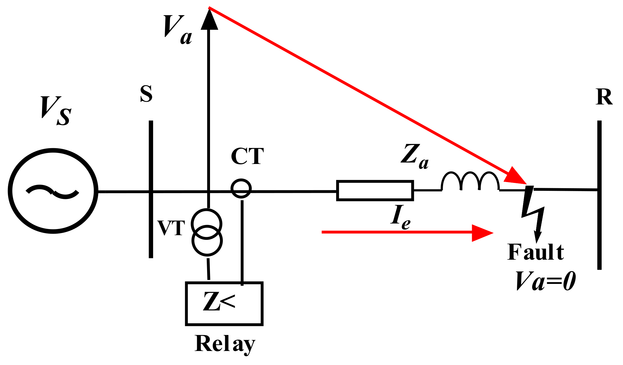
The input to the distance protection relay are the phase voltages and line currents transformed with voltage and current transformers, as shown in Figure 1. If a fault occurs on the protected line, the fault currents and voltages are monitored at the protection relay. The voltage drop along the transmission line is equal to the product of the fault current Ie and the impedance fault Za.
Distance relays must be compensated against the coupling effect between parallel lines since the current flowing in one phase of one line induces voltage onto adjacent phases of the other parallel line. This will otherwise affect the measured impedance under fault conditions. However, in the case of phase faults in one line, this is remedied by taking the difference between relevant phase quantities. For example, the impedance Zbc apparent to the b and c phase elements of a relay is calculated from [9]:
However, in the case of an earth fault, the residual compensation factor, k0, must be used,
where ZL0 is the zero-phase sequence line impedances and ZL1 is the positive phase sequence line impedances.
The apparent impedance seen by the relay for an earth fault in phase a is
where Za is the relay phase to earth impedance, Vph−e is the phase to earth short-circuit voltage at the relay located on the faulted phase, Iph is the short-circuit current in the faulted phase and Ie is the earth fault current.
The correct operation of earth fault elements in distance relays is highly dependent on the correct application of k0. Various relays vendors have different forms of naming, defining and applying these factors [10].
2.1. Modelling Overhead Line Mutual Coupling
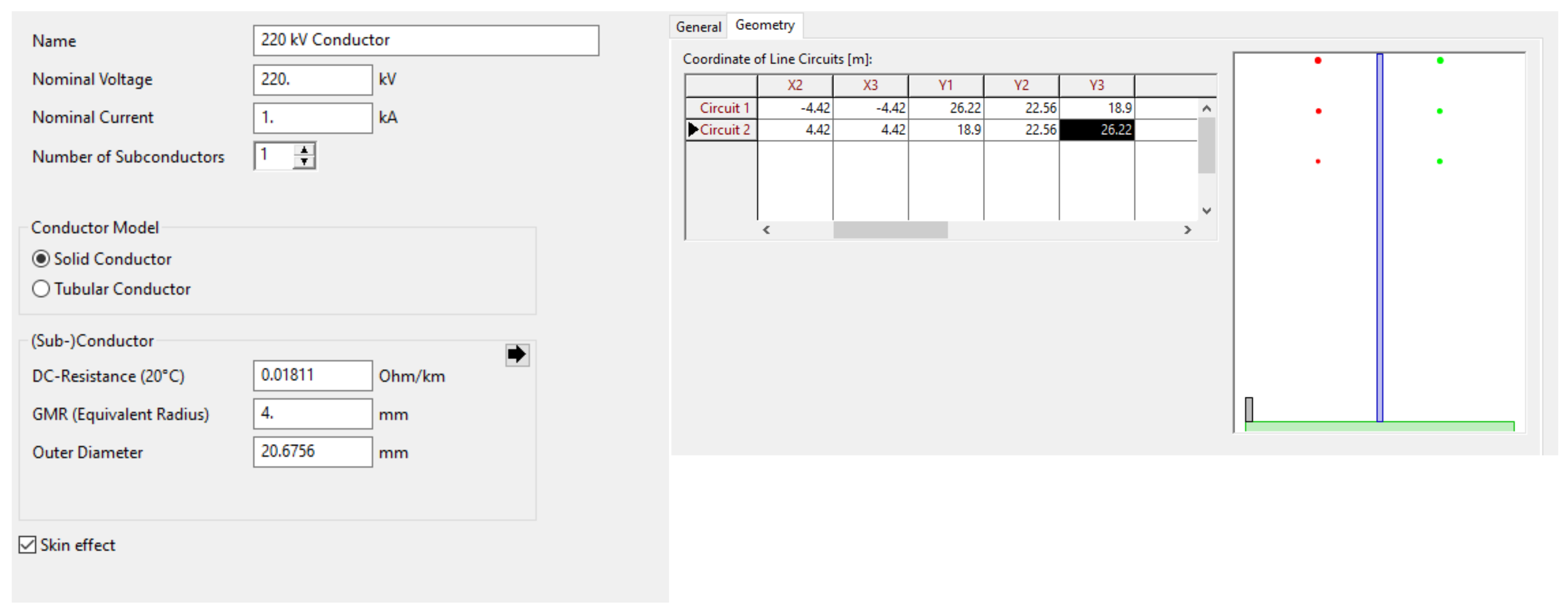
The 220 kV overhead lines’ mutual coupling is modelled based on their geometry of the conductors’ corresponding characteristics. The geometry is entered in PowerFactory using the X–Y coordinates of the phase conductors and ground wires, and the DC-resistance and bundling configuration must also be entered. The tower geometry used in the study of the 220 kV network is depicted in Figure 2. Geometrical mean radius (GMR) and the line’s outer diameter are provided from a manufacture’s datasheet. The specific earth resistance for the earth return path is assumed to have a typical value of 100 Ω/m, for a system frequency of 50 Hz. The maximum expected primary fault resistance for single phase-to-earth faults could also be calculated using the Warrington’s formula for arc resistance [11].
2.2. Quadrilateral Operation Characteristic for Distance Protection
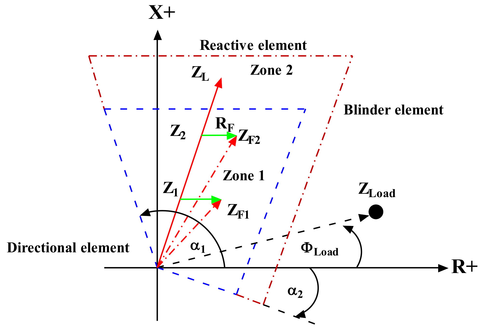
For earth-fault distance protection, fault resistance coverage is quite essential. A strong source with a short line typically does not result in adequate fault resistance coverage. Therefore, a polygonal (quadrilateral) characteristic can be used that allows independent reach settings and resistance coverage. A typical quadrilateral characteristic is shown in Figure 3. This characteristic is constructed using two directional characteristics, a reactance characteristic (X+) and a resistance characteristic (R+).
The impedance characteristic of most modern distance protection devices, both digital and numerical distance protection relays, use this characteristic to adjust their resistive and reactive reach independently. The quadrilateral characteristic allows for the setting of the resistive reach (R+) of the phase-to-phase measuring elements and the phase-to-earth measuring elements separately. By setting the compensate earth and mutual earth factors, the effects of zero-sequence mutual coupling on parallel operating lines can be accommodated. The quadrilateral impedance characteristics are highly flexible in terms of fault impedance coverage for both phase and earth faults [12].
During normal load conditions, the distance relay measures an apparent impedance according to the actual voltage and current at the relay location. Under normal conditions, the load angle (ϕLoad) lies in the range of ±30°. The apparent impedance is proportional to the load impedance ZLoad. Meanwhile, during fault occurrence, the impedance value jumps to a much smaller short-circuit impedance. The value depends on the distance between the location of the relay and the fault. Moreover, the fault resistance RF present in the faulted point will shift the fault impedance because it adds a resistive component to the measured impedance, as shown in Figure 3. To incorporate for the effects of a close-in fault, α1 is set to 115°, and the directional angle α2 for distance protection is adjusted to −15° [13].
Because of measurement errors, Zone 1 reach is usually set to 70–85% of the circuit length [14]. Generally, a grading factor of 85% is used for numerical relays. The factor of 85% is selected to consider measurement errors, inaccuracy of line impedance data and transducer errors. Zone 1 operates with no intentional time delay.
Zone 2 on a distance relay, where possible, should reach 20% beyond the line end. The Zone 2 reach must be set to cover the protected line plus 50% of the shortest adjacent line or 120% of the protected line, whichever is the greater [15]. Zone 2 usually has a time delay of approximately 0.4 to 0.5 s.
Zone 3 is mostly used as a back-up zone for Zone 1 and Zone 2. Zone 3 can also be used as a reverse function as back-up protection for busbars and transformers.
2.3. General Considerations for Parallel Lines
One of the most common problems, as shown in Figure 4 concerning distance protection of parallel lines ending at the same bus without mutual compensation, can be summarised as follows [16]:
- A tendency to underreach when both lines A and B are energised.
- A tendency to overreach when one of the lines is disconnected and earthed at both ends.
The coupling impedance Zmo between the zero-sequence systems of two lines with an earth-wire is estimated using the following equation [17]:
where is the depth of penetration in the ground, f is the frequency in Hz, is the specific resistance in Ω/m and Dab is the spacing in meters between the two conductors.
Alternatively, Zmo can be measured using test equipment when a line is out of service.
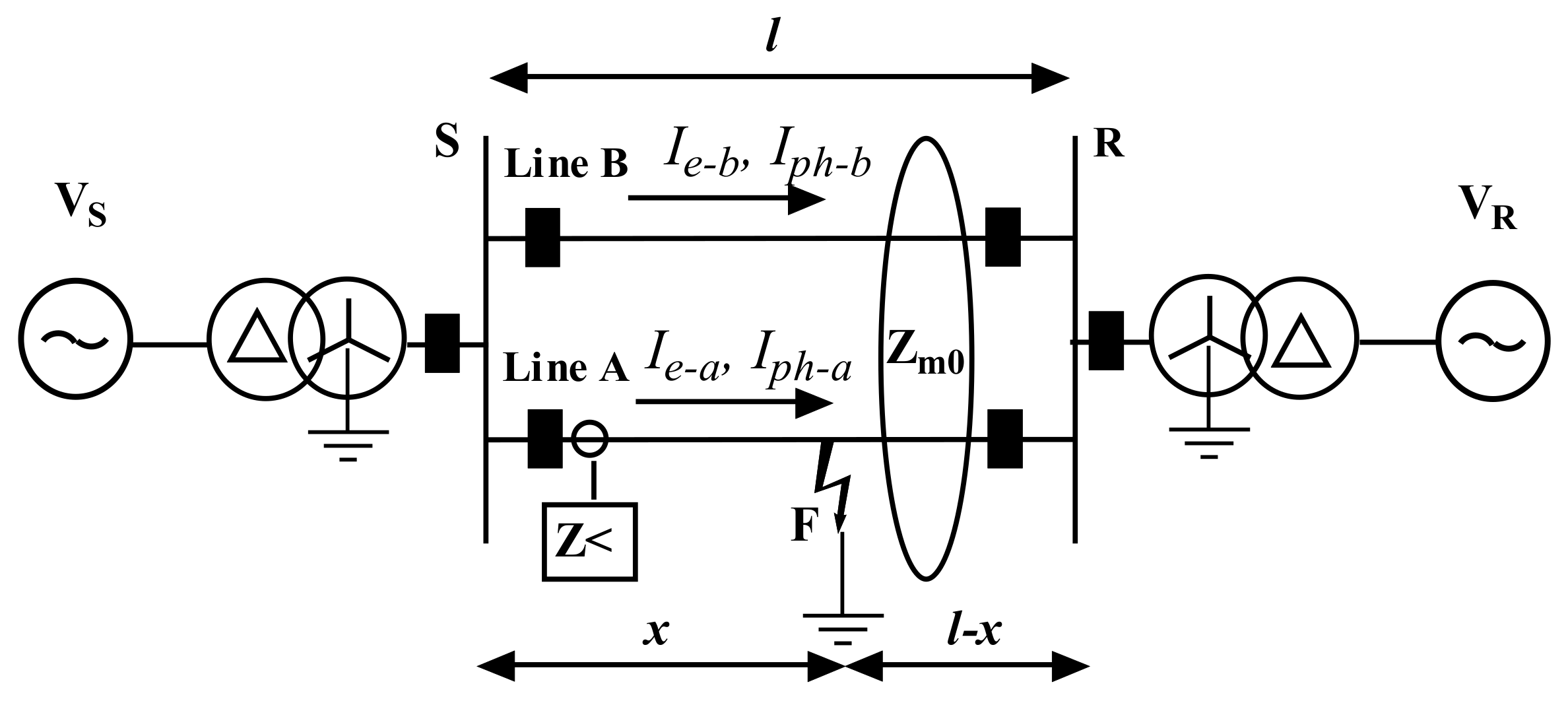
For the typical case of parallel lines A and B of length l, connected at the local and remote busbars, as shown in Figure 4, the apparent impedance Za of line A seen by the ground distance function for an earth fault in phase a is [18]
For the protection of phase-to-earth faults, a measuring error occurs. In general, the error appears because the parallel line earth current (Ie-b = 3 I0) induces a voltage Ie-b × (Zm0/3) into the fault loop.
From Equation (5), it can be deduced [16]:
- The error is proportional to the mutual coupling factor Zmo/3 ZLa.
- The error increases with the parallel line earth current Ie-b in relation to the relay current Iph-a + k0Iea.
- The relay underreaches when the parallel current Ie-b is in phase with Iph-a and Ie-a.
- The relay overreaches when Ie-b and Iph-a/Ie-a have opposite signs.
Short-circuit models are critical to developing settings and studying the effects of elements on the system. Simulations demonstrate that a relay, using fixed settings to protect 85% of the total line length, protects at a specific moment only 50% of the line, while at another moment its actual coverage is more than 100%, depending on the power system configuration [19].
For lines having only one supply at one end of the line, these values become even worse. The actual coverage is so widespread that the relay settings must be adapted to the double-circuit line’s operation mode.
In the following analysis, different scenarios and switching states of the parallel line system and the measured impedances are discussed. In each case, for a fault at the end of the parallel line, the following assumptions are made:
- The phase current and zero-sequence current of the protected line are equal (Iph−a = 3 I0)
- The parallel line residual current is equal to the residual current of the protected line.
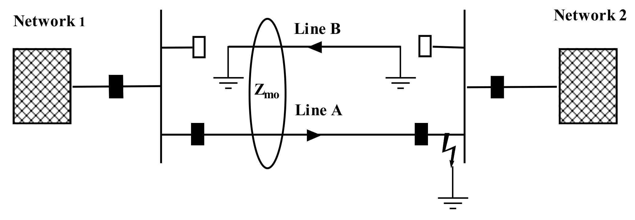
2.3.1. Double-Circuit Lines with Lines A and B Operated in Parallel
When zero sequence currents flow in the same direction in both lines, the measured impedance is too large, and the distance relays underreach, as shown in Figure 5. The measured impedance for a fault at the end of the parallel line is:
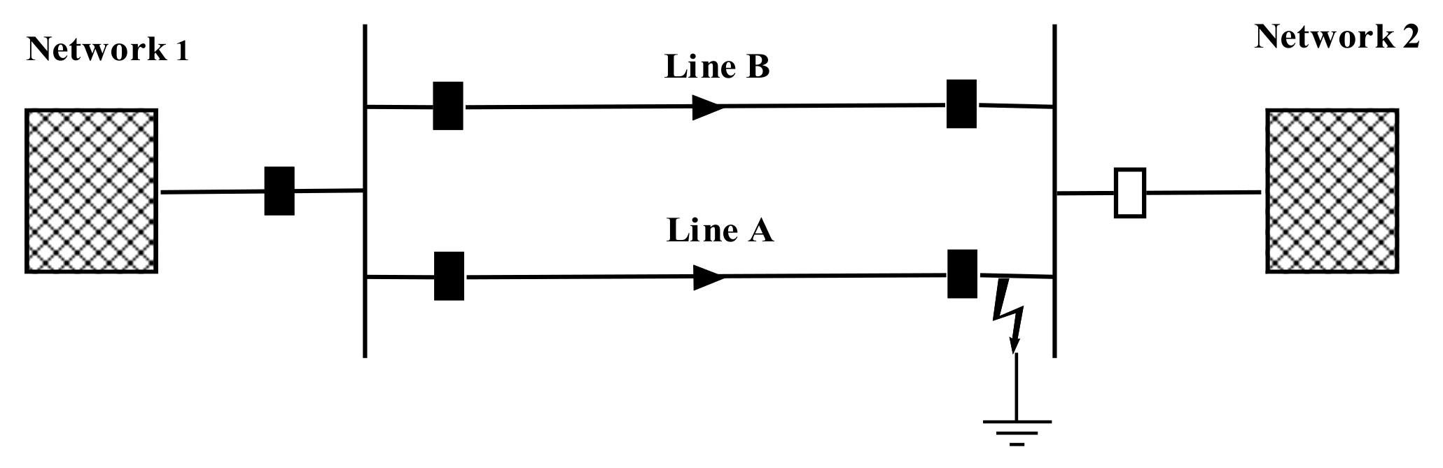
2.3.2. Double-Circuit Lines with Lines B Disconnected and Earthed at Both Ends
The worst case regarding the effects of zero sequence mutual coupling on distance relays’ performance is the overreaching. This occurs when the parallel circuit is out of service and earthed at both ends, as shown in Figure 6.
The apparent impedance seen by the relay in this case is
In this case, the earth fault current of the energised circuit can induce current flow in the opposite direction in the earth loop of the earthed circuit, causing the distance protection of the energised circuit to overreach. The distance protection overreaches as the earth impedance is reduced due to the parallel connection of both lines’ zero-sequence systems.
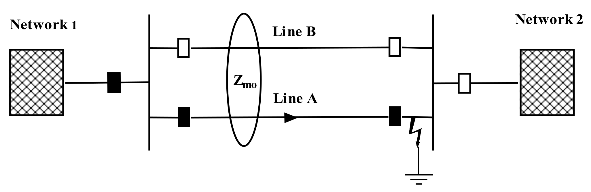
2.3.3. Double-Circuit Lines with Line B Disconnected (One or Both Ends Isolated)
With only one of the parallel circuits connected, the energised circuit’s distance protection measures the fault impedance correctly, as shown in Figure 7.
Modern distance protection devices often include an adaptive function to compensate for parallel lines’ mutual influence in case of earth faults. If the parallel line compensation function has been enabled, then the parallel line’s residual current will be included in the distance and directional measurement.
To compensate a ground distance relay such that the effect of the zero-sequence mutual coupling on its reach is minimal, another current transformer (CT) is needed. The distance protection has another measuring input to which the parallel line’s earth current is connected, as shown in Figure 8.
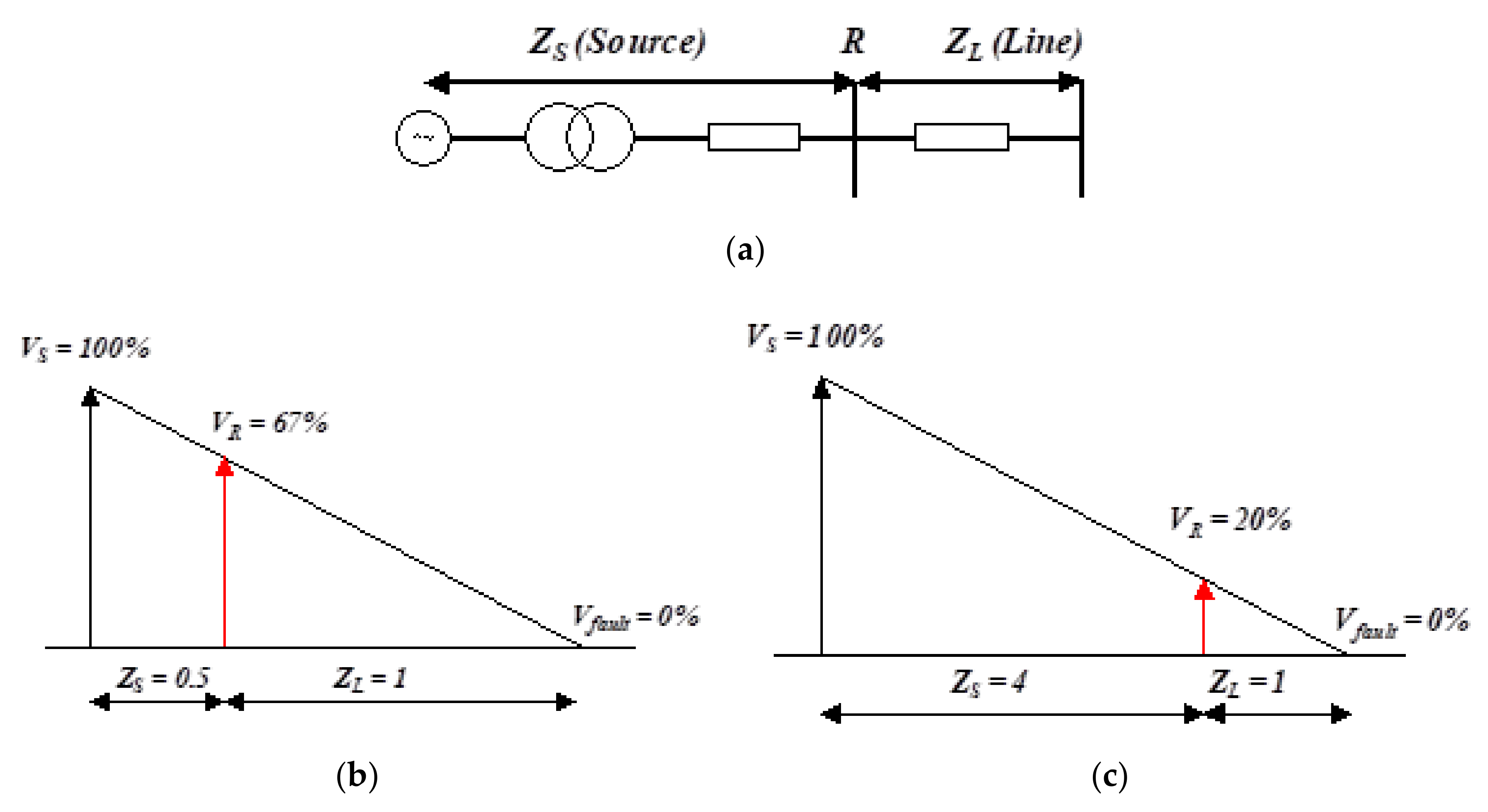
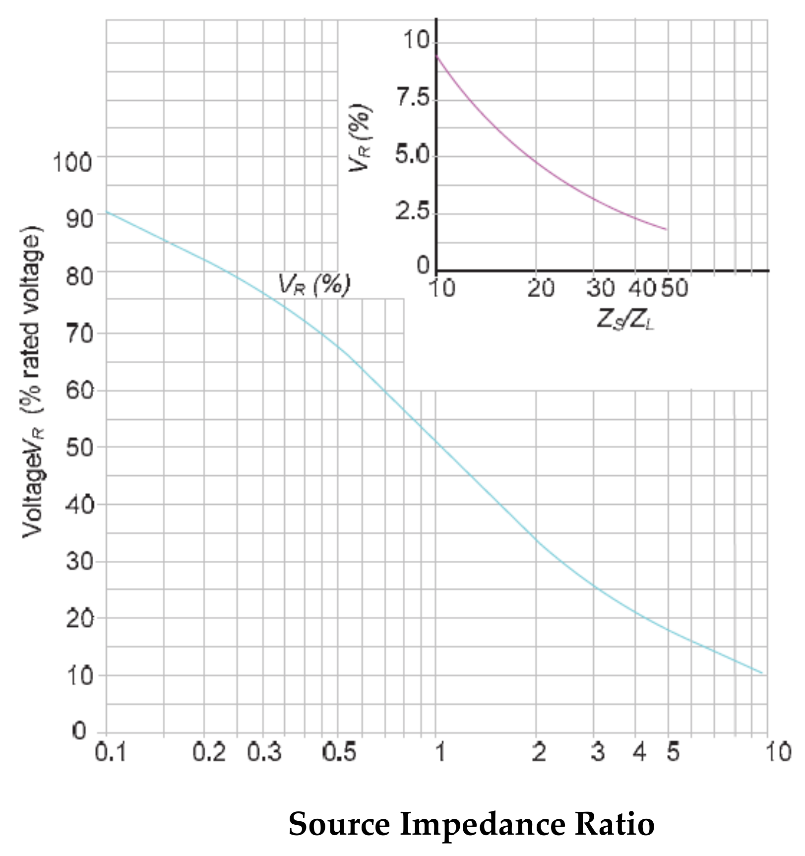
2.4. Source Impedance Ratio
The source impedance ratio (SIR) is the ratio of the source impedance, looking back from the relay location to the forward line impedance as shown in Figure 9a. It is a measure for the magnitude of the faulted-loop voltage seen by the relay. IEEE C37.113, [20] classifies line length based on SIR as follows:
- Long line (SIR < 0.5)
- Medium line (0.5 < SIR < 4)
- Short line (SIR > 4)
Short transmission lines present a challenge for distance protection settings. The protection relay can find it difficult to differentiate between an inner and outer zone fault. In recent years, SIRs have increased due to the growing amount of inverter-based generation. A high effective SIR will reduce the fault current, which will cause a reduced fault voltage.
The distance element’s accuracy will be impacted if the fault voltage drops below a certain voltage level. The source impedances can vary according to network configurations, such as adding new generation and other system elements. Distance relays should be tested for a range of SIR conditions encountered from different network configurations.
It can be seen from Figure 10 that for a SIR = 0.5, the voltage at the relay (R) will be 67% of the nominal value. Also, when the SIR > 4, the relay’s voltage is less than 20% nominal. As shown in Figure 10, a SIR above 30 decreases measurement accuracy and results in an incorrect distance relay operation.
The polarisation voltage measurement used by some relays can be taken from the faulted phase voltages (self-polarisation) or a scaled vector of the positive sequence voltage (cross-polarisation) [22].
When a fault is close to the protection relay, memory filters are often used to overcome the problem of voltage drop. Most intelligent electronic devices (IEDs) use the technique of healthy phase voltage polarisation combined with memory voltage polarisation. Memory voltage polarisation uses pre-fault voltage during certain type of faults. Quadrilateral relays tend to use an adaptive polarisation approach; they select the most suitable polarisation voltage depending on system configurations, fault case, magnitude of voltages and elapsed time after fault inception [23].
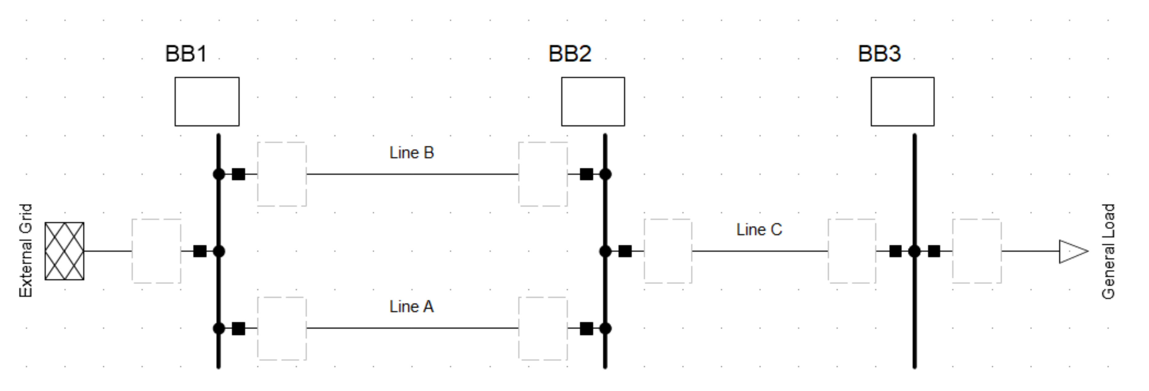
3. Results
To demonstrate the effects of mutual coupling, a simulation was conducted using DigSilent PowerFactory, as shown in Figure 11. It includes three 220 kV busbars and two transmission lines 50 km long, coupled at the same tower and feed from a common busbar. An external grid feeds a 200 MW load connected by the two coupled lines and a single 220 kV line, also 50 km long. The protection relay vendor uses a particular definition to determine the compensate earth faults and mutual coupling effects. Instead of directly using the k0 and km0 values as per the usual definition, it decouples the resistive and inductive components. Table 1 contains the overhead line data with the mutual zero-sequence values calculated from PowerFactory.
The compensate earth factor k0 can be calculated from knowing
The mutual earth factor km0 can be calculated from knowing
The CT used has a 1200/1 A ratio, and the voltage transformer was 220 kV/100 V. The line impedances were converted to the secondary side of the instrument transformers using
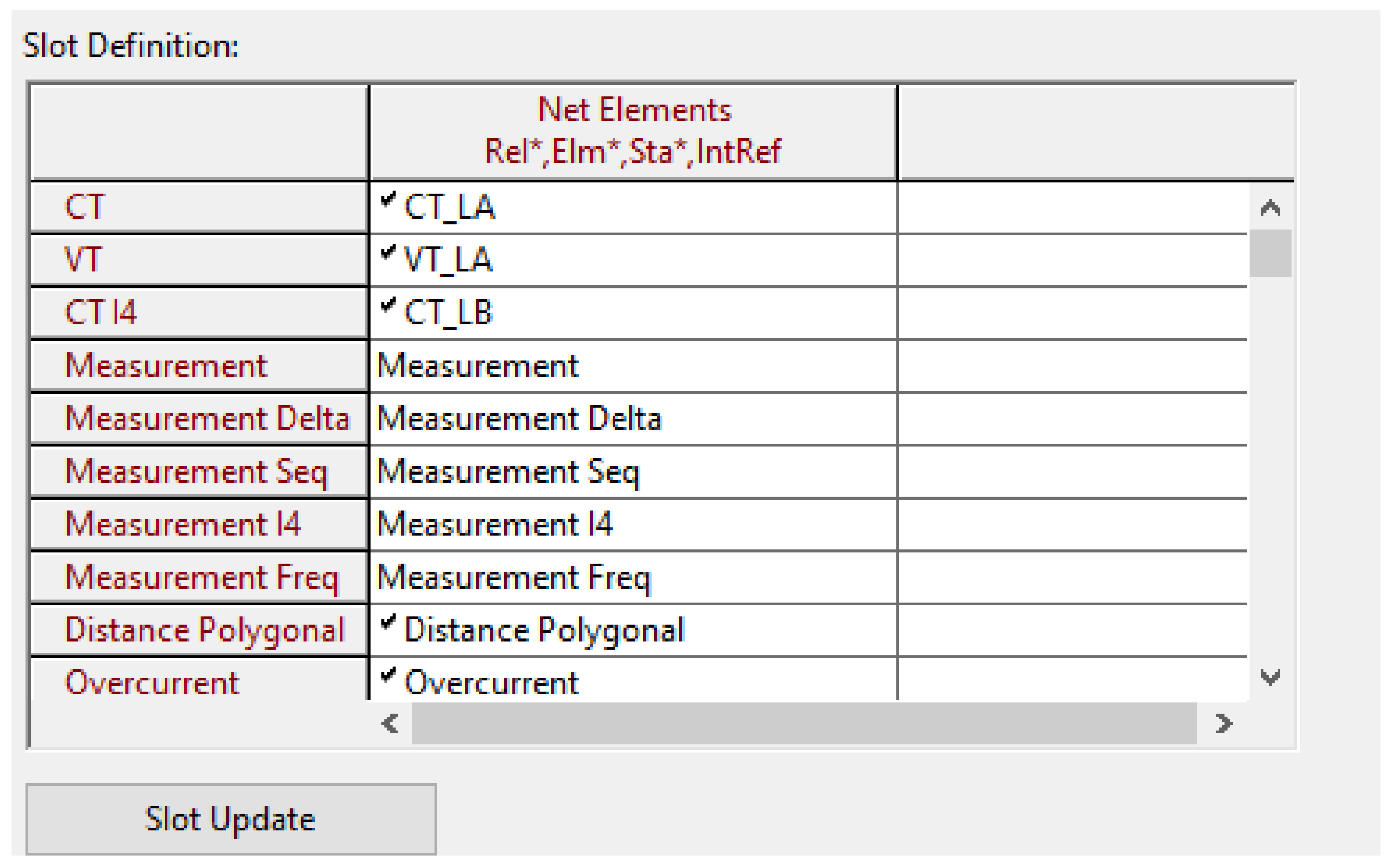
As shown in Figure 12, the distance protection relay slot includes a CT-mutual measuring (CTI4) input to which the earth current of the parallel line was connected.
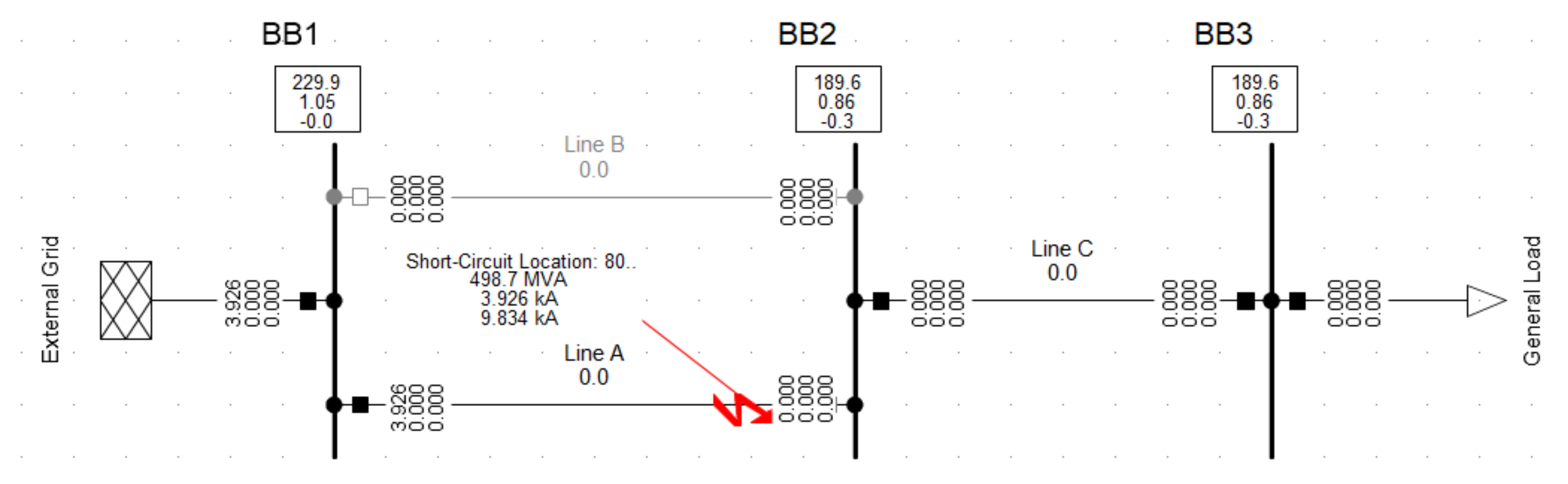
Table 2 shows the distance protection settings for Zones 1 to 3. Within DigSilent PowerFactory, and using the IEC 60909 method, an SLG fault, shown in Figure 13, was performed at 10% intervals of line A with the parallel line energised and de-energised, from where the relay is.
3.1. Simulation Results
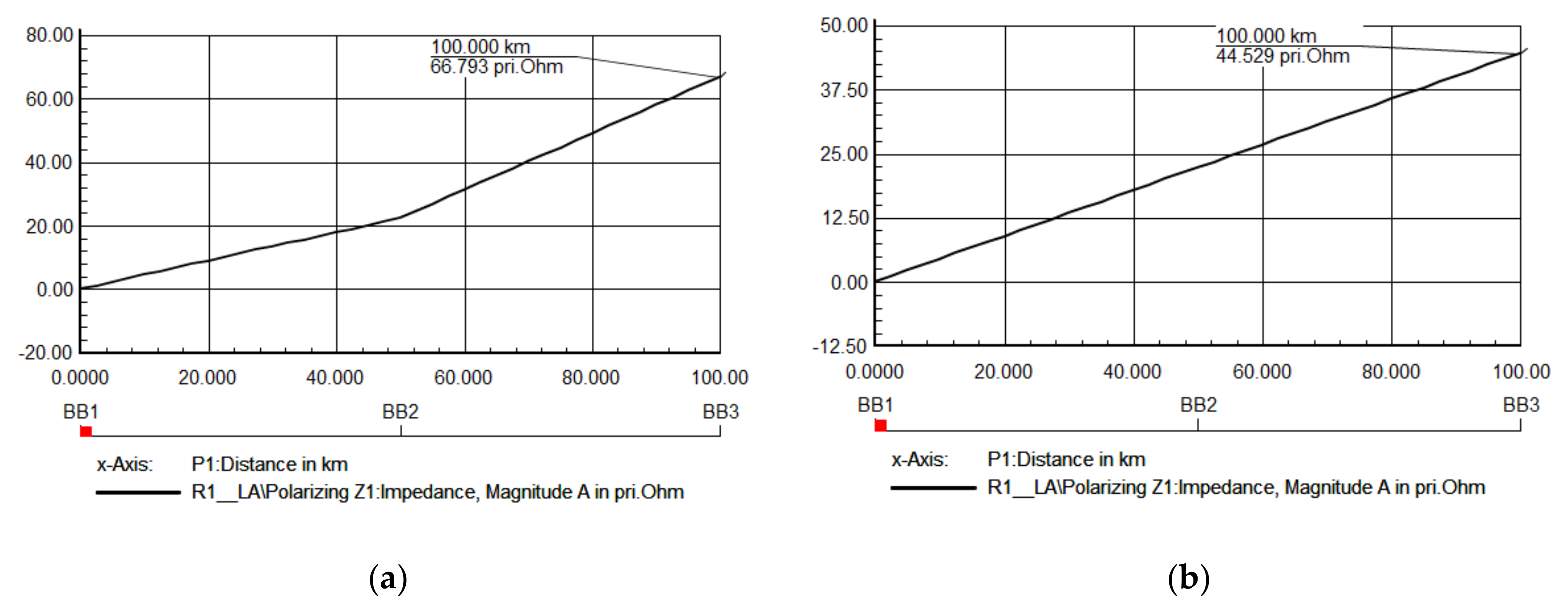
The short-circuit sweep time-distance diagrams are shown in Figure 14, from which it can be seen that the reach of the relay changes depending on the parallel line configuration. The short-circuit sweep displays the variation of network parameters with respect to the fault location.
Figure 14a shows that mutual coupling may increase or decrease the apparent impedance based on the fault’s location.
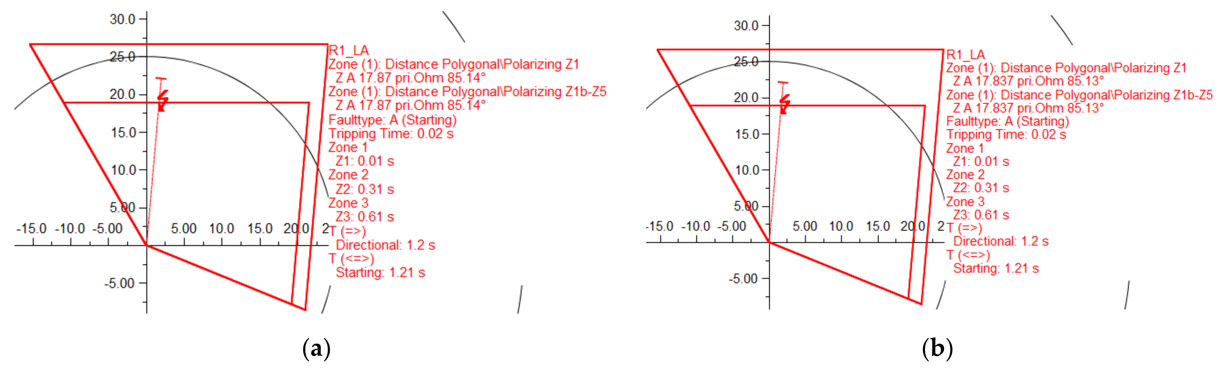
3.1.1. Analysis of an SLG at 80% on Line A with (a) Line A and B Connected and (b) Line B Disconnected. (Compensated)
An SLG fault is applied at 80% of the line. Mutual compensation has been applied. Figure 15a shows that when both lines are in service, the relay correctly measures the fault impedance. With line A compensated and line B disconnected, the relay of the energised circuit measures the fault impedance correctly, as shown in Figure 15b. The relay correctly operated for a fault in Zone 1 for both scenarios.
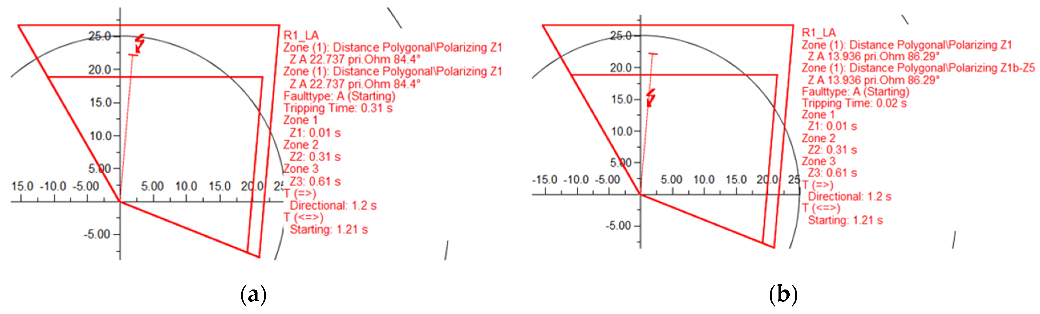
3.1.2. Analysis of an SLG at 80% on Line A (No Mutual Compensation)
To see the effect of the mutual coupling on the relay impedance measurement, the mutual earth factor values were set to zero without the proper compensation. Alternatively, the reference CT in the adjacent line can be disconnected. Line B was disconnected and earthed at both ends.
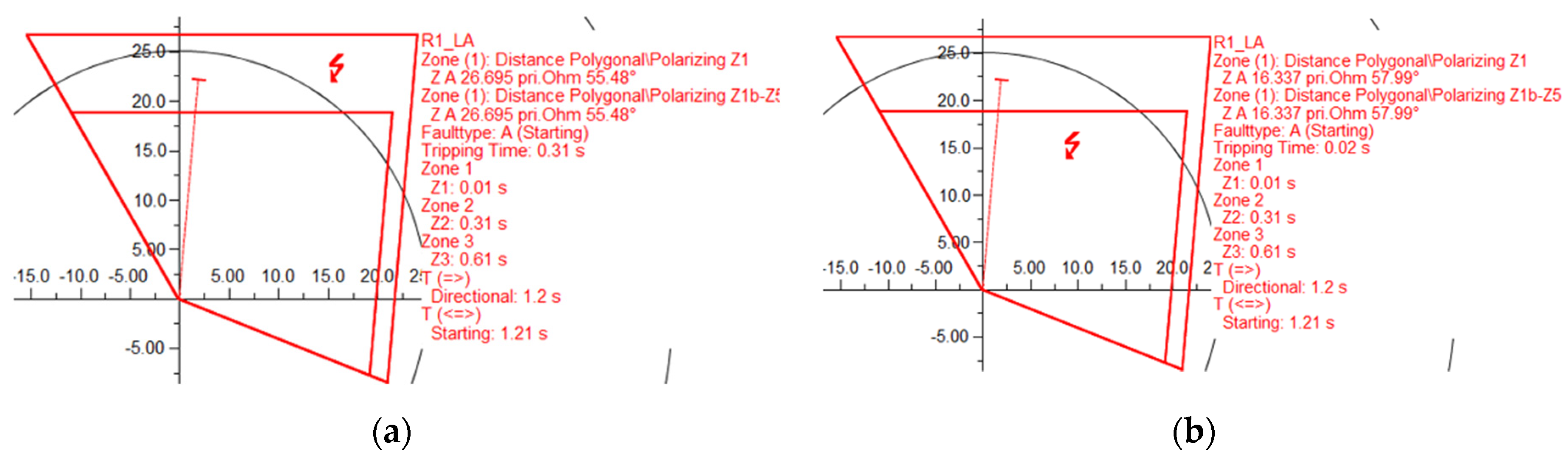
Figure 16a shows a resulting apparent impedance of 22.74 Ω for a line length of 17.86 Ω. This corresponds to an underreach of about 27%. It was observed that the fault (80%), this time determined by the relay, to be outside of Zone 1.
Figure 16b shows a different apparent impedance for the protection relay when one of the parallel lines is out of service and earthed on both ends. An SLG fault on the in-service line shows a considerable overreach of the impedance measurement is possible. The resulting apparent impedance of 13.94 Ω for a line length of 17.86 Ω corresponds to an overreach of about 22%.
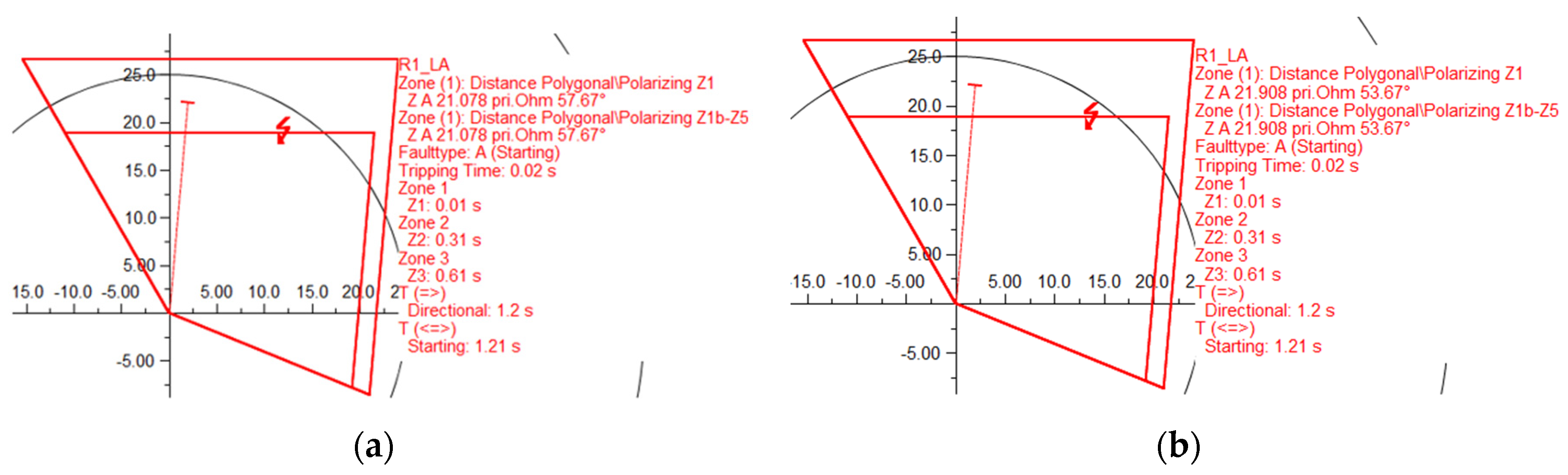
3.1.3. Analysis of an SLG at 80% on Line A, with (a) Line A and B Connected and (b) Line B Disconnected, with a Fault Resistance of 18 Ω (Compensated)
According to Warrington’s formula, the maximum expected fault resistance for an SLG fault was calculated to be 18 Ω. This is now included in the SLG fault path. It was observed that relay operated correctly for both scenarios, as shown in Figure 17.
3.1.4. Analysis of (a) an SLG at 80% on Line A with Both Lines Connected, and (b) with Line B Disconnected and Earthed with a Fault Resistance of 18 Ω (No Mutual Compensation Applied)
Figure 18a shows an SLG fault is applied at 80% of line A with both lines connected. Figure 18b shows the result of Line B disconnected and earthed. Mutual compensation has been removed for both cases.
It was observed that the fault (80%) was outside of zone 1 as shown in Figure 18a. Figure 18b shows that overreaching occurs of the relay again. This is due again to the mutual coupling effect.
For comparison, Table 3 shows the results obtained in the simulation for different scenarios.
4. Discussion
Due to the zero-sequence mutual coupling, and depending on the feeding arrangement, the neutral current’s magnitude and direction in the parallel line, a distance protection relay will either overreach or underreach.
When both parallel lines are in service, and an earth fault occurs on one of the lines, a considerable increase in the apparent impedance measurement is possible. A single line-to-ground fault at 90% of the line corresponds to an underreach of about 34%. The maximum value occurs for a fault at the remote end (100%) of the line length.
When one of the parallel lines is taken out of service and earthed, an induced neutral current can flow through the line. A considerable decrease of the apparent impedance measurement is possible for a single line-to-ground earth fault on the in-service line. Simulations of the line show a decrease in the apparent impedance for a line length. A single line-to-ground fault at 90% of the line corresponds to an overreach of about 25%.
Zero-sequence coupling compensation can overcome many of the distance relay problems on double-circuit lines. The compensation of the parallel lines’ mutual effects by referencing the residual current from the parallel line into the distance relay of the protected line is complex and can lead to incorrect operation and testing. Further, many system configurations will defeat this method of compensation. It is also impossible to compensate when several lines are in parallel or when a line is out of service.
Most distance protection relays accommodate a setting value for the mutual coupling impedance. This allows the relay to compensate without using a coupling CT and avoiding any under or overreach of any tripping zone.
IEDs will allow the use of different setting groups to be accommodated for different line scenarios. However, this will require a thorough study and simulation of the system to accommodate the different settings. In the future, the IEC 61850 communication standard should implement a method of updating settings to adapt the relay to a different network and feeding arrangement.
The COMTRADE file standard can be used to exchange various types of fault, test and simulation data between a protection relay and DigSilent. The COMTRADE files generated from simulations can be used to test the distance relays. The files can be played back to distance protection relays to determine if they operate correctly for different scenarios.
5. Conclusions
Inaccurate zero-sequence impedance settings caused by mutual coupling strongly affects zone reaches, and the accuracy of distance protection relays in the event of a single line-to-ground fault. This distance protection relay must be compensated for the coupling between parallel lines to avoid maloperation during faults and different system configurations.
Techniques such as referencing the residual current from the parallel line are complex and are impossible to use when several lines are in parallel or when a line is out of service.
The calculation of Z0 is influenced by the soil return path properties, such as soil resistivity, and other parallel buried conductors such as cables and pipes. All of these properties are estimated and therefore, can make the calculation inaccurate.
The best way to ensure that the distance protection relay settings are correct requires a thorough knowledge of the relay’s reach and system configurations and actual measurement values of Z1 and Z0.
Author Contributions
Methodology, simulation, writing—original draft preparation, M.O.D.; Review and editing, supervision, N.B., J.C. and E.C. All authors have read and agreed to the published version of the manuscript.
Funding
This research received no external funding.
Data Availability Statement
Data is contained within the article.
Conflicts of Interest
The authors declare no conflict of interest.
References
- O’Donovan, M.; Cowhey, E.; Barry, N.; Connell, J. The Effects of Mutual Coupling Compensation on Distance Protection of Parallel Lines. In Proceedings of the 2020 55th International Universities Power Engineering Conference (UPEC), Torino, Italy, 1–4 September 2020; pp. 1–6. [Google Scholar]
- Holbach, J.; Vadlamani, V.; Lu, Y. Issues and Solutions in Setting a Quadrilateral Distance Characteristic. In Proceedings of the 2008 61st Annual Conference for Protective Relay Engineers, College Station, TX, USA, 1–3 April 2008; pp. 89–104. [Google Scholar]
- Tziouvaras, D.A.; Altuve, H.J.; Calero, F. Protecting mutually coupled transmission lines: Challenges and solutions. In Proceedings of the 2014 67th Annual Conference for Protective Relay Engineers, College Station, TX, USA, 31 March–3 April 2014; pp. 30–49. [Google Scholar]
- Das, S.; Santoso, S.; Gaikwad, A.; Patel, M. Impedance-based fault location in transmission networks: Theory and application. IEEE Access 2014, 2, 537–557. [Google Scholar] [CrossRef]
- Donovan, M.O.; Cowhey, E.; Barry, N. Application oriented testing of power transmission lines and fault clearing. In Proceedings of the 2016 51st International Universities Power Engineering Conference (UPEC), Coimbra, Portugal, 6–9 September 2016; pp. 1–6. [Google Scholar]
- Bian, J.J.; Slone, A.D.; Tatro, P.J. Protection system misoperation analysis. In Proceedings of the 2014 IEEE PES General Meeting | Conference & Exposition, National Harbor, MD, USA, 27–31 July 2014; pp. 1–5. [Google Scholar]
- Sellwood, V.; Klapper, U.; Kruger, M.; Kaiser, S. A new technique for setting distance protection and fault location by measurement of transmission line system impedance characteristics. In Proceedings of the 8th IEE International Conference on AC and DC Power Transmission, London, UK, 28–31 March 2006; pp. 197–199. [Google Scholar]
- Hulka, L.; Klapper, U.; Putter, M.; Wurzer, W. Measurement of line impedance and mutual coupling of parallel lines to improve the protection system. In Proceedings of the CIRED 2009-20th International Conference and Exhibition on Electricity Distribution-Part 1, Prague, Czech Republic, 8–11 June 2009; pp. 1–4. [Google Scholar]
- Moore, P.J.; Muhalhel, K.; Booth, C. Distance relay behaviour on mixed voltage, double circuit lines. In Proceedings of the 2008 IET 9th International Conference on Developments in Power System Protection (DPSP 2008), Glasgow, Scotland, 17–20 March 2008; pp. 649–653. [Google Scholar]
- Sorrentino, E. Comparison of five methods of compensation for the ground distance function and assessment of their effect on the resistive reach in quadrilateral characteristics. Int. J. Electr. Power Energy Syst. 2014, 61, 440–445. [Google Scholar] [CrossRef]
- Terzija, V.V.; Koglin, H. New approach to arc resistance calculation. In Proceedings of the 2001 IEEE Power Engineering Society Winter Meeting. Conference Proceedings (Cat. No.01CH37194), Columbus, OH, USA, 28 January–1 February 2001; Volume 782, pp. 781–787. [Google Scholar]
- Schweitzer, E.O.; Kasztenny, B. Distance protection: Why have we started with a circle, does it matter, and what else is out there? In Proceedings of the 2018 71st Annual Conference for Protective Relay Engineers (CPRE), College Station, TX, USA, 26–29 March 2018; pp. 1–19. [Google Scholar]
- Hong, Q.; Booth, C.; Dyśko, A.; Catterson, V. Design of an intelligent system for comprehensive validation of protection settings. In Proceedings of the 13th International Conference on Development in Power System Protection 2016 (DPSP), Edinburgh, UK, 7–10 March 2016; pp. 1–7. [Google Scholar]
- O’Donovan, M.; Cowhey, E.; Barry, N.; Connell, J. Assessment of Power Swing Blocking Functions. In Proceedings of the 2020 55th International Universities Power Engineering Conference (UPEC), Torino, Italy, 1–4 September 2020; pp. 1–6. [Google Scholar]
- Eirgrid. ALL-ISLAND TRANSMISSION SYSTEM PERFORMANCE; Ireland. 2014. Available online: https://www.eirgridgroup.com/site-files/library/EirGrid/All-Island-Transmission-System-Performance-Report-2019.pdf (accessed on 21 May 2020).
- CIGRE. Modern Distance Protection Functions and Applications; CIGRÉ: Paris, France, 2008. [Google Scholar]
- Siemens. Applications for SIPROTEC Protection Relays; Siemens AG: Munich, Germany, 2005. [Google Scholar]
- Worldwide, A.G. Network Protection & Automation Guide; Alstom Grid: Saint-Ouen, France, 2011. [Google Scholar]
- Jongepier, A.G.; Sluis, L.v.d. Adaptive distance protection of a double-circuit line. IEEE Trans. Power Deliv. 1994, 9, 1289–1297. [Google Scholar] [CrossRef]
- IEEE Guide for Power System Protection Testing; IEEE Std. C37.233–2009; IEEE: Piscataway, NJ, USA, 2009; pp. 1–124. [CrossRef]
- Thompson, M.J.; Somani, A. A tutorial on calculating source impedance ratios for determining line length. In Proceedings of the 2015 68th Annual Conference for Protective Relay Engineers, College Station, TX, USA, 30 March–2 April 2015; pp. 833–841. [Google Scholar]
- Brusilowicz, B.; Schulz, N.N. Polarizing Voltage Generating Method for Distance and Directional Protection Elements. IEEE Trans. Power Deliv. 2021, 36, 74–83. [Google Scholar] [CrossRef]
- Ziegler, G. Numerical Distance Protection: Principles and Applications, 4th ed.; John Wiley & Sons: Hoboken, NJ, USA, 2011; p. 419. [Google Scholar]
Figure 1.
Distance protection principle.

Figure 2.
Conductor types and tower geometry of a 220 kV transmission line.

Figure 3.
Quadrilateral characteristics with zones of distance protection.

Figure 4.
Parallel circuit fed from both ends.

Figure 5.
Both circuits in parallel operation fed from a single source.

Figure 6.
Parallel circuit switched off and earthed on both ends.

Figure 7.
Parallel circuit disconnected (one or both ends isolated).

Figure 8.
Mutual compensation using the zero-sequence current from line B into the ground distance relay in line A.
Figure 8.
Mutual compensation using the zero-sequence current from line B into the ground distance relay in line A.

Figure 9.
(a) Relationship between source-to-line ratio of a power system, (b) SIR < 0.5; (c) SIR > 4 [21].
Figure 9.
(a) Relationship between source-to-line ratio of a power system, (b) SIR < 0.5; (c) SIR > 4 [21].

Figure 10.
Variation of relay voltage with the system source-to-line impedance ratio [18].
Figure 10.
Variation of relay voltage with the system source-to-line impedance ratio [18].

Figure 11.
Schematic single-line diagram of a 220 kV transmission system.

Figure 12.
Slot definitions in protection relay with mutual coupling CT_L2 included.

Figure 13.
Single line-to-ground (SLG) fault at line A with line B disconnected.

Figure 14.
Short-circuit sweep (a) Both lines connected and (b) line B disconnected.

Figure 15.
R-X plot for an SLG fault at 80% of line A, with (a) both lines connected (b) line B disconnected.
Figure 15.
R-X plot for an SLG fault at 80% of line A, with (a) both lines connected (b) line B disconnected.

Figure 16.
R-X plot for an SLG fault at 80%, with (a) both lines A and B, connected with no compensation (b) line B disconnected and earthed with no compensation.
Figure 16.
R-X plot for an SLG fault at 80%, with (a) both lines A and B, connected with no compensation (b) line B disconnected and earthed with no compensation.

Figure 17.
R-X plot for an SLG fault at 80%, with (a) both line A and B connected and fault resistance of 18 Ω with compensation (b) line B disconnected.
Figure 17.
R-X plot for an SLG fault at 80%, with (a) both line A and B connected and fault resistance of 18 Ω with compensation (b) line B disconnected.

Figure 18.
R-X plot for an SLG fault at 80%, with (a) both line A and B connected and fault resistance of 18 Ω with no compensation (b) line B disconnected and earthed at both ends.
Figure 18.
R-X plot for an SLG fault at 80%, with (a) both line A and B connected and fault resistance of 18 Ω with no compensation (b) line B disconnected and earthed at both ends.


Table 1.
Overhead line parameters.
| Line Data | Ω/km |
|---|---|
| Positive sequence reactance X1 | 0.4437 |
| Positive sequence resistance R1 | 0.0378 |
| Zero-sequence reactance X0 | 1.3680 |
| Zero-sequence resistance R0 | 0.1786 |
| Mutual zero-sequence reactance Xm0 | 0.9243 |
| Mutual zero-sequence resistance Rm0 | 0.1408 |
Table 2.
Distance relay protection setting parameters.
| Grading (Reach) | +Rreach Ω | +Rph-ph Ω | +Xph-e Ω | Time Delay (s) |
|---|---|---|---|---|
| Zone 1 | 18.85 | 10.89 | 19.89 | 0.0 |
| Zone 2 | 26.62 | 12.79 | 21.79 | 0.3 |
| Zone 3 | 66.54 | 16.00 | 25.00 | 0.6 |
Table 3.
Result of simulations for a compensated and uncompensated double-circuit line (RF = 0 Ω).
| Fault Location Line A (50 km) | No Compensation both Lines Connected (% Error) | With Compensation both Lines Connected (% Error) | No Compensation One Line Earthed (% Error) |
|---|---|---|---|
| 10% | 2.20 | 0.00 | −2.78 |
| 20% | 4.57 | 0.00 | −5.58 |
| 30% | 7.20 | 0.03 | −8.36 |
| 40% | 10.31 | 0.06 | −11.13 |
| 50% | 13.74 | 0.08 | −13.76 |
| 60% | 17.60 | 0.11 | −16.70 |
| 70% | 22.18 | 0.14 | −19.47 |
| 80% | 27.45 | 0.17 | −22.45 |
| 90% | 33.67 | 0.21 | −25.03 |
| 100% | 41.90 | 0.80 | −27.41 |
Publisher’s Note: MDPI stays neutral with regard to jurisdictional claims in published maps and institutional affiliations. |
© 2021 by the authors. Licensee MDPI, Basel, Switzerland. This article is an open access article distributed under the terms and conditions of the Creative Commons Attribution (CC BY) license (https://creativecommons.org/licenses/by/4.0/).
Share and Cite
MDPI and ACS Style
O Donovan, M.; Barry, N.; Connell, J.; Cowhey, E. Mutual Coupling Compensation Techniques Used for Distance Protection of Parallel Lines. Energies 2021, 14, 1982. https://doi.org/10.3390/en14071982
AMA Style
O Donovan M, Barry N, Connell J, Cowhey E. Mutual Coupling Compensation Techniques Used for Distance Protection of Parallel Lines. Energies. 2021; 14(7):1982. https://doi.org/10.3390/en14071982
Chicago/Turabian StyleO Donovan, Michael, Noel Barry, Joe Connell, and Eoin Cowhey. 2021. "Mutual Coupling Compensation Techniques Used for Distance Protection of Parallel Lines" Energies 14, no. 7: 1982. https://doi.org/10.3390/en14071982
Note that from the first issue of 2016, this journal uses article numbers instead of page numbers. See further details here.