Article

Basaltic Glass Fibers from Industrial Wastes: A Laboratory-Scale Technical Feasibility Study

1
Settore Ricerca e Sviluppo R&D, Stazione Sperimentale del Vetro ScpA, Via Briati 10, Murano, 30141 Venice, Italy
2
ORI Martin SpA, Via Cosimo Canovetti 13, 25128 Brescia, Italy
3
Mechanical and Industrial Engineering Department, University of Rome “ROMA TRE”, Via Vasca Navale 79, 00146 Rome, Italy
4
Chemistry for Technologies Laboratory, Department of Mechanical and Industrial Engineering, University of Brescia, Via Branze 38, 25123 Brescia, Italy
5
Consorzio Interuniversitario Nazionale per la Scienza e Tecnologia dei Materiali (INSTM), Via G. Giusti 9, 50121 Florence, Italy
*
Author to whom correspondence should be addressed.
Crystals 2022, 12(3), 359; https://doi.org/10.3390/cryst12030359
Submission received: 28 January 2022 / Revised: 15 February 2022 / Accepted: 5 March 2022 / Published: 8 March 2022

Abstract

:
This study demonstrated the physical–chemical and technical feasibility of recycling EAF slag granulated by rapid cooling with gas to produce continuous glass fibers with a basalt-like composition. To adjust the chemical composition, a silica fume-based secondary raw material was used, together with other additives. Different compositions were tested: 50% EAF slag and 50% silica fume (sample C1); 40% EAF slag, 50% silica fume and 10% Na2O (sample C2); 40% EAF slag, 50% silica fume, 5% Na2O and 5% K2O (sample C3); 20% EAF slag, 57% silica fume, 10% Na2O and 13% alkali earth oxides (sample C4); 26% EAF slag, 35% silica fume, 7% CaO and 12% Na2O (sample C5); 26% EAF slag, 35% silica fume, 4% CaO and 15% Na2O (sample C6). The last composition allowed obtaining fibers up to 5–6 m long, with a diameter between 60 and 180 µm. The process involved using a refractory material crucible with a calibrated bottom orifice as a single nozzle bushing. The optimal temperature range for fiber forming was between 1115 and 1125 °C, with a linear drawing speed of about 2 m/s. Preliminary mechanical tests were performed. Based on these results, potential further recycling applications of granulated EAF slag in the production of basalt-like glass for noncontinuous fiber production for mechanical reinforcement or for thermal–acoustic insulation can also be foreseen.

1. Introduction

The circular economy concept responds to the demand for a more sustainable consumption of natural resources [1]. The circular economy changes focus on reusing, adjusting, renewing and recycling materials and products at the end of their service life. From this new perspective, electric arc furnace (EAF) slags that were typically considered “waste” must now be transformed into a resource, for example through innovative technological solutions that fully enhance their positive features and transform them into valuable secondary raw materials for a different production process [2,3,4,5,6,7]. Several successful initiatives in the transformation of the steel industrial sector from a linear economy to a circular one have already been reported for slags, dusts, iron scale and spent refractories [8,9,10]. The steel industry has long held a strategic place in the EU economy, fostering innovation, growth and employment. To face the downturn in steel demand after the economic crisis and ensure an environmentally and economically sustainable future for the sector, the European Commission is actively promoting and supporting technological research and development initiatives. Steel is closely linked to numerous industrial sectors such as automotive, construction, electronics and renewable industries [11]. The Italian steel industry is among the strongest in Europe, boasting several quality excellences and occupying the second place (after Germany) for production volume. Combining competitiveness on the global market and environmental sustainability is the primary challenge that the steel industry must face today, representing a fundamental milestone for the economy [12].
The quantity of by-products in steel production is remarkable, close to 15% of the total steel production output [13]. These materials are often suitable to be valued as secondary raw materials, constituting a valid alternative to primary natural or synthetic raw materials in many applications [2,3,4,5,6,14]. Today, their uses are mainly limited to road paving and construction industry, and about 25% are landfilled, a solution that in the future is bound to become less and less sustainable, both from the environmental and economic points of view.
Many projects address the challenge posed by exploiting the EAF slags, proposing new eco-innovative industrial application alternatives, potentially opening new essential markets for steelworks by-products. Our research primary objective is to ensure a new value for the slags by using them in several innovative applications, such as ceramic coatings, composites and 3D printing. This matches the research strategies to promote the circular economy in steel production, with a cross-cutting approach to value-added.
A recent production method is based on fast cooling of the slag with high-pressure cold air [15]. As a result, slag particles instantly form spherical shapes and are deposited in the air-cooled area. Slag particles thus formed are finer in size (<4.75mm), as shown in Figure 1. This fine aggregate of spheric slags is a promising and advantageous alternative to natural sand, also in terms of workability, water content and cement mechanical requirements [6,16,17].
Moreover, its composition makes it a potential ingredient for producing basalt-like materials.
Basalt is a dark-colored, fine-grained, igneous rock composed mainly of plagioclase and pyroxene minerals. It most commonly forms as an extrusive rock, such as a lava flow, but can also form in small intrusive bodies, such as an igneous dike or a thin sill [18].
Fiber-reinforced composites are becoming more and more relevant for applications including automotive, aerospace, marine and building applications. Carbon footprint and sustainability are the key factors in today’s world, and composites are often an optimized solution for these problems [19].
Basalt fiber has properties that are far superior to glass fiber. Basalt fibers resist flame, continuous temperatures of up to 815 °C and chemicals (both acids and bases); are excellent acoustic and electrical insulators; and have good mechanical properties. Because basalt remains functional down to −260 °C, it can be used also for cryogenic applications [20,21]. For these reasons, UE has recently granted EUR 3 million to a company for the development of a technology to use basalt fibers in 3D printing. In addition, NASA proposed a 3D-printed basalt fiber composite structure intended for Mars habitation.
Basalt fiber products are used in the automotive sector as building materials in nonwoven needled felts or as insulation materials for exhaust pipes, such as sheaths and strips. Moreover, basalt fiber is the most environmentally friendly, high-temperature resistant material when it comes to both manufacturing and recycling. Basalt is mainly used to produce two types of fiber-based products: rock wool for thermo-acoustic insulation applications and continuous fiber for applications such as reinforcement yarn for composites.
For both products, natural basaltic rock is melted at temperatures of about 1500 °C together with other raw materials, needed to adjust the final chemical composition, and the two processes leading to rock wool or continuous fiber differ mainly in the specific forming modes by which the melt is transformed into thin filaments with a diameter of a few tens of microns.
Rock wool is produced using a rotating centrifuge that radially projects thin jets of molten glass, accompanied by the melt’s cooling and solidification; then, the resulting fibers are collected and fixed by polymer resin as a disordered mat. Continuous fiber is produced by forcing glass to pass through multinozzle bushings that produce several thin filaments of molten glass that are then rapidly cooled and protected with a polymer-based thin coating called “sizing” by means of nebulization of an aqueous suspension; the continuous fibers are then spun and wound around a reel/spool for further processing.
EAF slags are mainly composed of oxides: FeO/Fe2O3, CaO, MgO, SiO2, MnO and Al2O3. The phase diagram (Figure 2) shows that the composition of the EAF slag must be principally enriched in SiO2 to obtain materials with a composition similar to that of effusive stones such as basalt [22].
The use of EAF slags to produce rock wool has been already reported. The results showed that the use of slags does not affect the main qualities of rock wool (i.e., thermal insulation and fire resistance) [24].
Figure 3 shows the continuous basalt fiber production process [25]: the crushed rock is transported from the silos to the melting furnace, at the exit of which the channels convey the molten glass to the bushings. The fibers are sized, twisted and finally wound in coils or transformed into different finished products [26]. Thanks to this process, it is possible to obtain a fiber with high mechanical and chemical resistance, especially in acid and basic environments, particularly suitable for reinforcing composite materials not only with polymer matrix but also with cement (impossible for common glass fibers, which would be dissolved by the alkaline environment).
Our research faces the challenge posed by the exploitation of steel slag and the need to find new alternative and eco-innovative industrial applications potentially capable of opening up new important markets for steel waste. The aim is to guarantee new value for steel mill slag, using it as a raw material in various innovative applications, in line with the search for strategies to promote the circular economy in the steel sector, with a transversal approach to added value.
In particular, in this paper, we report the production of basalt-like fibers that are a promising substitute for raw materials.

2. Materials and Methods

ORI Martin (Brescia, Italy) and Metalleghe (Flero, Italy) provided the EAF slags and the silica fume, respectively.
SEM images were obtained with an FEI Helios Nanolab 600 FEI dual-beam SEM-FIB instrument.
XRD measures were performed by means of X’Pert Pro MPD diffractometer, PANalytical, Almelo, The Netherlands (anode material: Cu; generator settings: 40 mA, 40 kV). Crystallography Open Database (COD) was used for crystalline phase identification.
XRF analysis was realized following ISO 12677:2011 with a Thermo ARL Advant’XP instrument, Thermo Scientific, Waltham, MA, USA.
The furnace used for laboratory-scale melting tests was an electrically heated 30 × 30 × 30 cm Carbolite furnace with radiating heating elements, capable of reaching a maximum temperature of 1550 °C, with a maximum controlled heating rate of 5 °C/min, designed to withstand severe thermal shocks (possibility of opening the loading door even at maximum temperature).
The laboratory-scale continuous fiber drawing preliminary trials were performed using a bespoke testing rig built in-house by Stazione Sperimentale del Vetro; the system features an electrically heated vertically oriented 20 cm diameter tubular furnace, reaching a maximum temperature of approximately 1300 ± 1 °C, with a 4 cm diameter hole on the bottom running through the whole insulation layer.
A series of refractory inserts allows safely positioning and homogeneously heating a small refractory crucible (of max. 7–8 cm diameter) with a calibrated orifice on the bottom (e.g., 8 mm), containing the glass sample. The piloting thermocouple is placed at approximately the same height as the orifice to ensure precise control of drawing temperature.
Below the furnace, a variable-speed electric motor drives a pair of metal counter-rotating rollers that are used to pull the fiber.
By adjusting the interplay between the furnace temperature and the drawing speed, it is possible to control the final diameter of the fibers: too high furnace temperatures lead to excessive diameter fibers (still incandescent when in contact with the traction rollers); fine tuning the drawing temperature to lower values yields smaller diameter fibers.
For tensile strength measures, an appropriate system was assembled. The fibers were fixed to a support and an increasing weight was applied to the opposite end. The tensile strength of each fiber was calculated by dividing the applied force by the area of the resistant fiber section.

Physical–Chemical Characterization of the Raw Materials

The EAF slag used in the test was obtained by rapid cooling with a gas jet. The product has a granular form with grain size d < 10 mm (see Figure 4). The granulated slag is spherical and compact. There are mainly three phases. The prevailing phases show evident, differently branched dendritic formations consisting of Fe, O, Ca, Al, Si and Mn. The minority phase has a globular morphology consisting of magnesium oxide with thickening of Fe on the surface.
Diffraction patterns of SBS were compared with those of slags produced by the same plant with the conventional water-cooling process. The results suggest that SBS can have different structural features showing a high percentage of amorphous material and of spinel phases.
The chemical composition of raw materials is reported in Table 1. The granulated slag has an iron content of more than 43% by weight, expressed as Fe2O3; CaO (22%); and about 10% SiO2. In the silica fume, the SiO2 content is about 91%, with alkali and alkaline earth oxides and traces of other elements accounting for 5%. These data allow us to define the first mixture and the needed additives to obtain a composition similar to basaltic rocks suitable to produce fibers.
The EAF slag phases were identified by XRD (Figure 5). Different pseudo-magnetite phases (Fe3O4) and dicalcium silicate (larnite (Ca2SiO4)) were identified. Magnetite (Fe3O4), magnesioferrite (Fe2MgO4), titanomagnetite (Fe2.75Ti0.25O4), chromite (FeCr2O4) and manganocromite (MnCr2O4) have a similar crystalline structure with only slightly different cell parameters; therefore, their peaks and diffraction intensities are overlapped, except for the highest angles. The peaks not highlighted in Figure 5 belong to the larnite phase. None of the identified phases contains aluminum, which is likely in the amorphous or solid solutions.
The silica fume is almost completely in the amorphous phase.
EAF slags differ in chemical composition, and in general, a significant inhomogeneity may be found. However, in view of the process adopted for slag production in this research, a very good homogeneity of the composition is obtained. As far as the potential difference in the composition due to the raw materials used in the EAF process, the variability is not expected to be larger than that found in basalt rocks (see Figure 2).

3. Results and Discussion

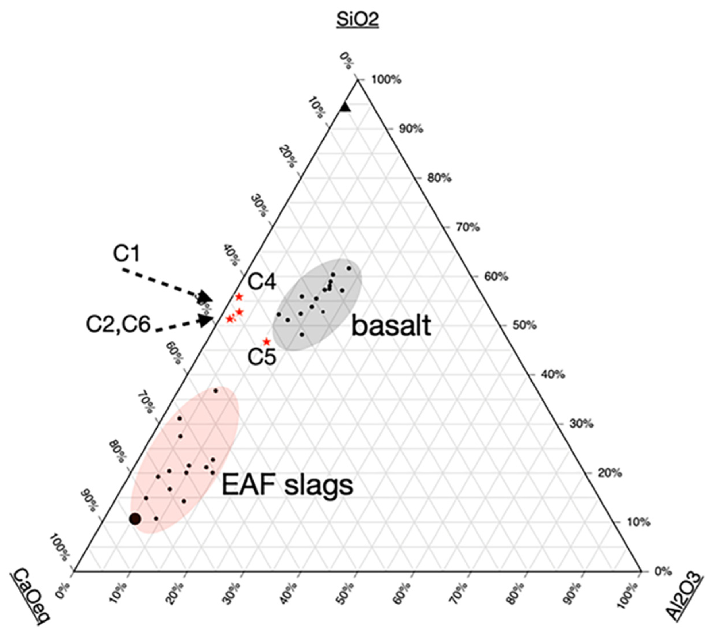
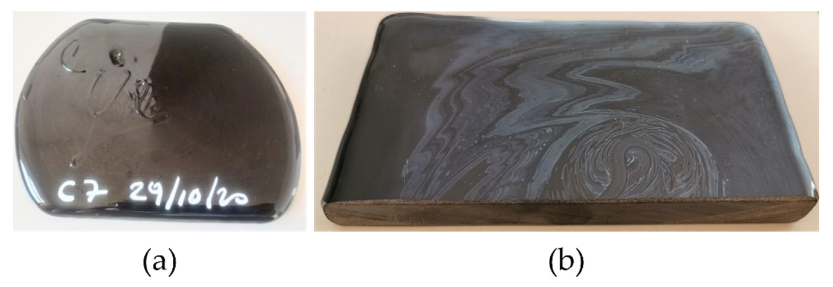
3.1. Design of the Basaltic Glass Composition, Laboratory-Scale Melting and Fiber Drawing Tests and Fine Tuning of the Batch Formulation

The first batch formulation was a mixture of 50% EAF slag and 50% silica fume, named C1. The melting process was carried out in a refractory crucible within an electric furnace at the operating temperature of 1400 °C; the melt was mechanically homogenized and then cast. The melt was viscous, and, after solidification, the sample was annealed for one hour at 600 °C, during which crystals formed both on the surfaces and in the bulk of the glass (Figure 6).
The chemical composition of sample C1 (Table 1), though having percentages of silica and most other oxides similar to basaltic rocks, contained much less alumina, which is a critical constituent in determining the final glass viscosity and thus the technical feasibility of fiber production.
The crystalline phases formed during cooling were different from those found in the EAF slag, and peaks in agreement with pyroxene species were identified: calcium silicates rich in magnesium and/or iron, and possibly aluminum and titanium (Figure 7). The main pyroxenes are augite, diopside and hedenbergite, all containing about 50 mol% calcium. Augite can contain up to 25 mol% alumina, while in diopside and hedenbergite the maximum is 1.5%. While augite and magnetite were recognized, diopside (MgCaSi2O6) and hedenbergite cannot be distinguished in the XRD pattern.
Based on the elemental composition, the identified crystalline phases and the phase diagrams, we estimated that after annealing the sample consists of about 40% in weight of amorphous and 60% crystalline phases. This percentage of crystallinity is too high for fiber production; therefore, additives were added to the batch formulation to reduce its devitrification propensity.
Different vitrifiable mixtures were tested with the aim of approaching the composition of basalt rocks and obtaining a glassy material suitable for drawing continuous fibers at temperatures below 1400 °C. Alkaline oxides were added to decrease the viscosity of the glass and reduce the devitrification phenomena, representing a critical issue for the production of the fibers. In fact, crystal phases could lead to the occlusion of the nozzles and may determine fiber breakage.
Two new compositions, C2 and C3, were tested at first. In these samples we reduced EAF slag to 40 wt%, maintaining 50% silica fume and adding 10% Na2O in sample C2 and 5% Na2O and 5% K2O in sample C3, with both alkali oxides being added into the mix as carbonates (see Table 1).
The mixtures were fused in silico-aluminous crucibles for 3 h at 1400 °C and cast onto a cold metal plate to form thick glass plates (about 15 × 10 × 2 cm3) that were subsequently annealed at 580 °C for 1 h, yielding the specimens shown in Figure 8.
Despite the relevant devitrification observed, a first fiber drawing trial was performed with sample C2 to investigate its behavior: part of the thick glass plate produced by the experimental casting was roughly crushed, and some shards were loaded into a silico-aluminous refractory crucible with a height of 10 cm and a mouth diameter of 7 cm, with a small 8 mm diameter orifice on the bottom.
We observed two concurring phenomena:
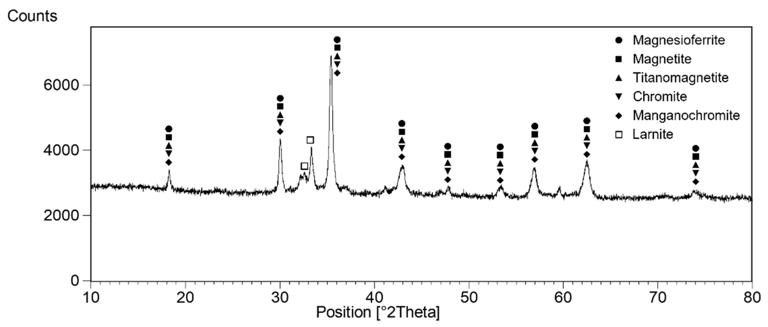
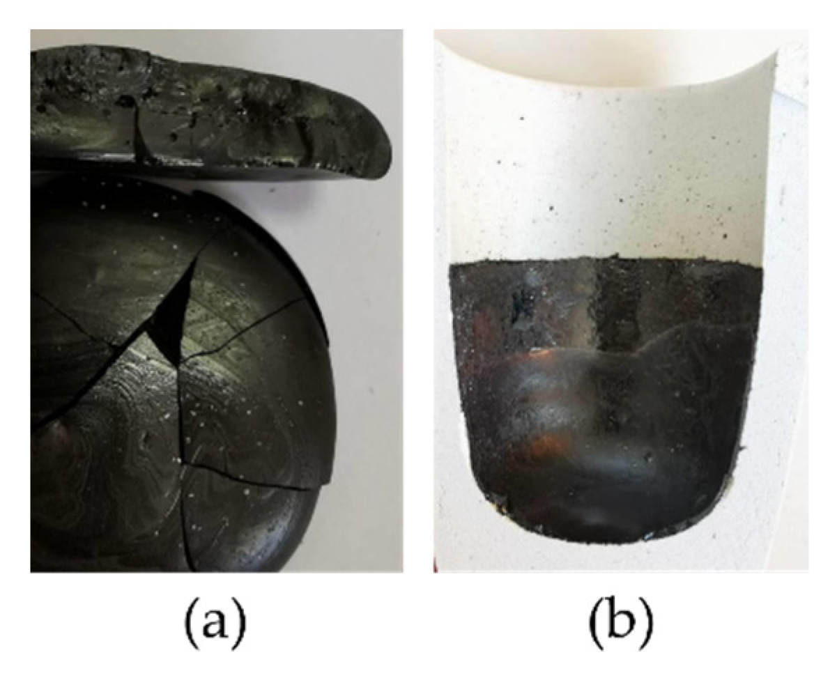
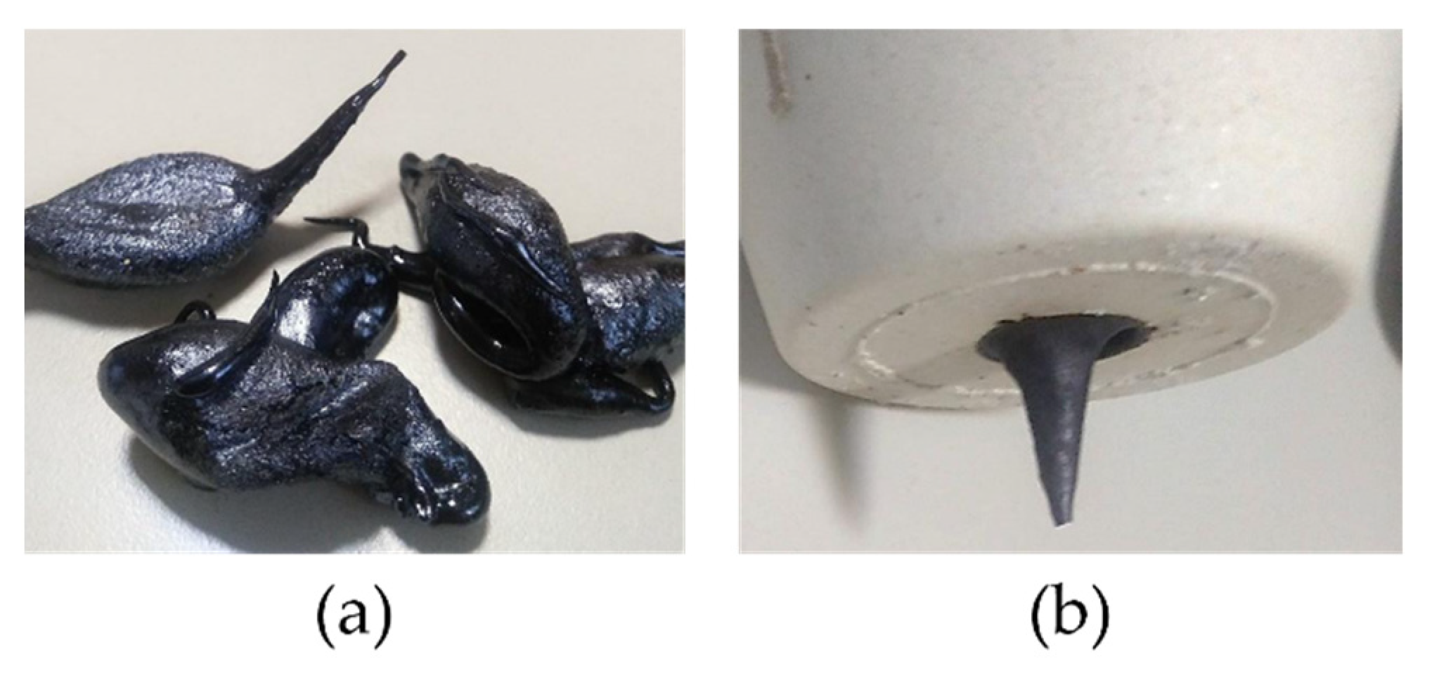
  • The development of Fe-rich crystalline phases at the interface with the refractory material in the nozzle/hole area at the bottom of the crucible;
  • The air-mediated oxidation of the Fe2+ of the melt to Fe3+ in the same area, resulting in a local increase in glass viscosity (Fe2+ acts as a fluxing network modifier, while Fe3+ is much less effective as a flux than Fe2+).
Both these phenomena concurred to form a semirigid shell around the melt flowing down from the crucible hole (see Figure 9b), which hindered further material flow towards the bottom of the test rig, causing in the end the periodic fall of large glass drops with semirigid outer shell, instead of the formation of a continuous fiber.
Despite the content of alkaline modifiers being around 10%, sample C2 was found to be quite “short”, characterized by strong variations in viscosity in correspondence to modest temperature changes. The pouring of glass drops stopped completely decreasing the temperature by less than 5 °C.
Sample C3 was not tested, since it would have likely exhibited the same issues.
To reduce the formation of crystalline phases within the melt and minimize the changes in viscosity corresponding to local variations in the redox equilibrium, three new batch formulations (C4, C5 and C6) were developed. The alkaline content was increased, and the slag was reduced to lower the Fe2O3 percentage. The composition of the samples is reported in Table 1.
The C4 glass was melted at 1400 °C for 3 h in a small refractory crucible directly suitable for fiber drawing trials in the lab-scale testing rig; no casting was performed, but the crucible was rapidly cooled in air to minimize crystal formation. The final product had a glossy and smooth surface, a sign of minimum devitrification upon cooling.
However, when the sample was placed in the fiber-drawing system and heated, at temperatures of around 800 °C, the glass gave rise to strong devitrification phenomena, rapidly increasing its volume and breaking the crucible.
The XRD analysis of the crystallized sample showed 40% amorphous phase and 60% diopside (MgCaSi2O6). Close to the upper surface, hedenbergite (CaFeSi2O6) was also identified. The reason for this behavior is probably related to the fact that the sample’s composition is close to that of diopside, and Fe could favor the formation of Hedenbergite at the surface.
In samples C5 and C6, we did not add magnesium-bearing raw materials (e.g., dolomite), and, instead, we increased the Al content by adding kaolin (Al2Si2O5(OH)4) in sample C5 and metakaolin (precalcined kaolin: Al2O3 · 2 SiO2) in C6. The two formulations mainly differed in the percentages of calcium and sodium oxides: 7% CaO (introduced as calcium carbonate) and 12% Na2O for sample C5 and 4% CaO and 15% Na2O for sample C6.
In both samples, the viscosity behavior was significantly shifted towards higher temperatures, allowing the optimal drawing temperature to be reached in a range unfavorable to crystal formation.
Samples C5 and C6 were melted in small crucibles at 1400 °C for 3 h and left to cool quickly in calm air. Both glasses were then tested in the laboratory-scale fiber drawing rig.
At about 1120 °C, sample C5 began to flow from the crucible in the form of a thin filament. However, in the end, the thermal inertia of the furnace brought the glass up to about 1126 °C, and due to the “short” viscosity behavior of the melt, the crucible started to pour larger and larger amounts of molten glass, basically emptying itself in less than 2 min. The product appeared vitreous and glossy, so presumably there was no devitrification during the fiber production.
From this evidence, it is possible to state that the C5 composition is suitable for fiber production, even though it is characterized by significant viscosity variations at 1120 °C, likely due to the high alkaline earth content, so drawing fibers from it could require a very tight control on melt temperatures in the bushing.
C6 composition was subsequently tested following the same procedure, eventually demonstrating much better fiber drawing aptitude: the sample began to produce a thin thread of glass at about 1115 °C, and the viscosity remained perfectly suitable for fiber drawing up to 1120 °C; no excessive flow of glass (like in the C5 test) was encountered for temperatures slightly exceeding the optimal drawing interval. The laboratory-scale system produced fibers about 2.5 m long, with a diameter of 150–180 microns.
Thus, the C6 sample, containing 26 wt% black granulated EAF slag, 35% silica fume, 20% metakaolin, 15% sodium oxide (added as Na2CO3) and 4% calcium oxide (added as CaCO3), proved to be suitable to produce thin fibers, demonstrating the chemical–physical and technical feasibility of producing basaltic glass fibers from granulated black slag.
Further melting and fiber drawing tests were carried out with the C6 batch formulation to confirm the mixture’s fusibility and fiber formation potential, as well as to produce samples for preliminary mechanical characterizations.
Two additional samples with the same composition of C6, named C7 and C8, were produced in larger crucibles (approx. 1 kg of molten material) following the same protocol. However, sample C7 was cast on a cold metal plate and cooled in air, while C8 was cast and then annealed for 1 h at 580 °C. As shown in Figure 10, the samples were found to be smooth and shiny, even if the C8 sample showed some surface crystallization.
After coarse crushing, the C8 glass underwent fiber drawing tests, yielding very positive results and thus confirming the possibility of fiber production with the bespoke laboratory-scale testing rig in an optimal temperature interval ranging from 1115 to 1125 °C, at linear drawing speeds of about 2–3 m/s. Fibers 5–6 m long with a 60–180 µm diameter were produced, as shown in Figure 11.

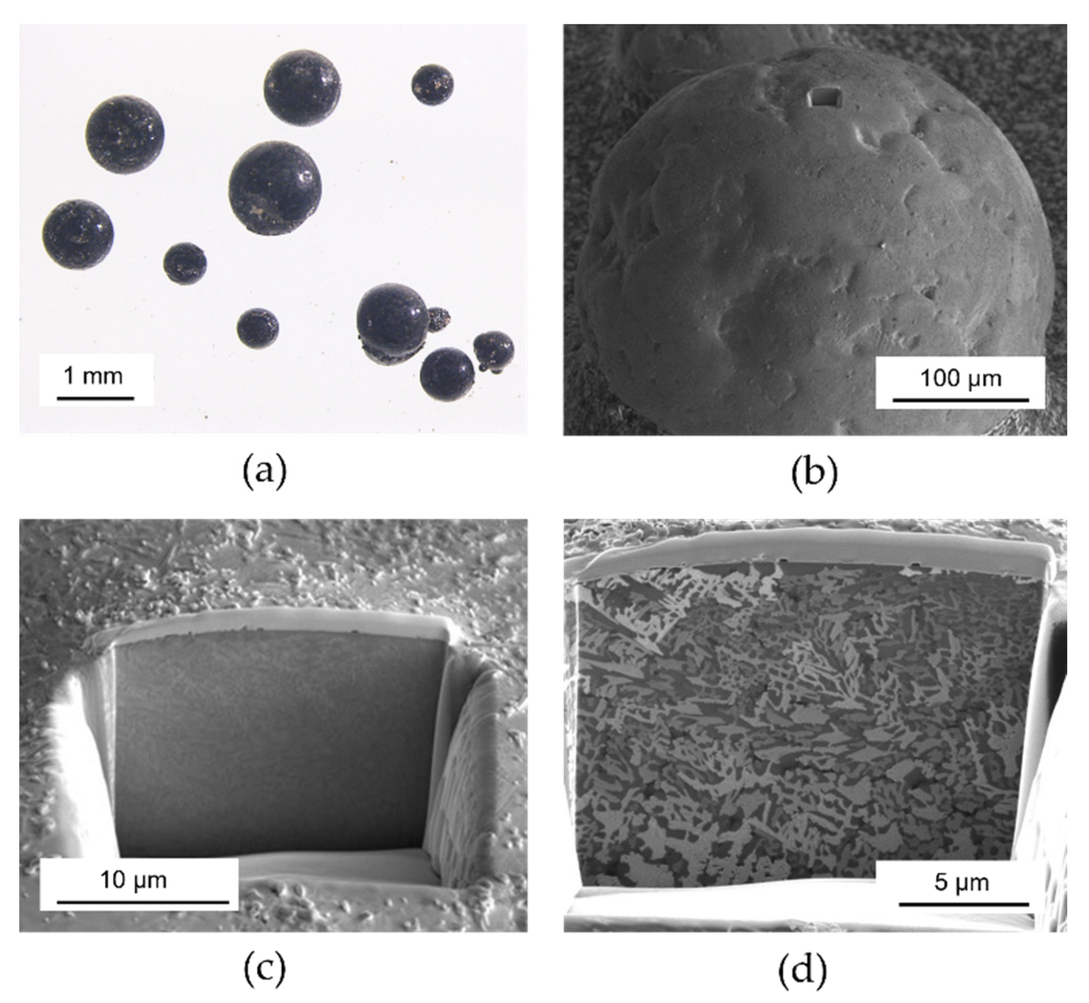
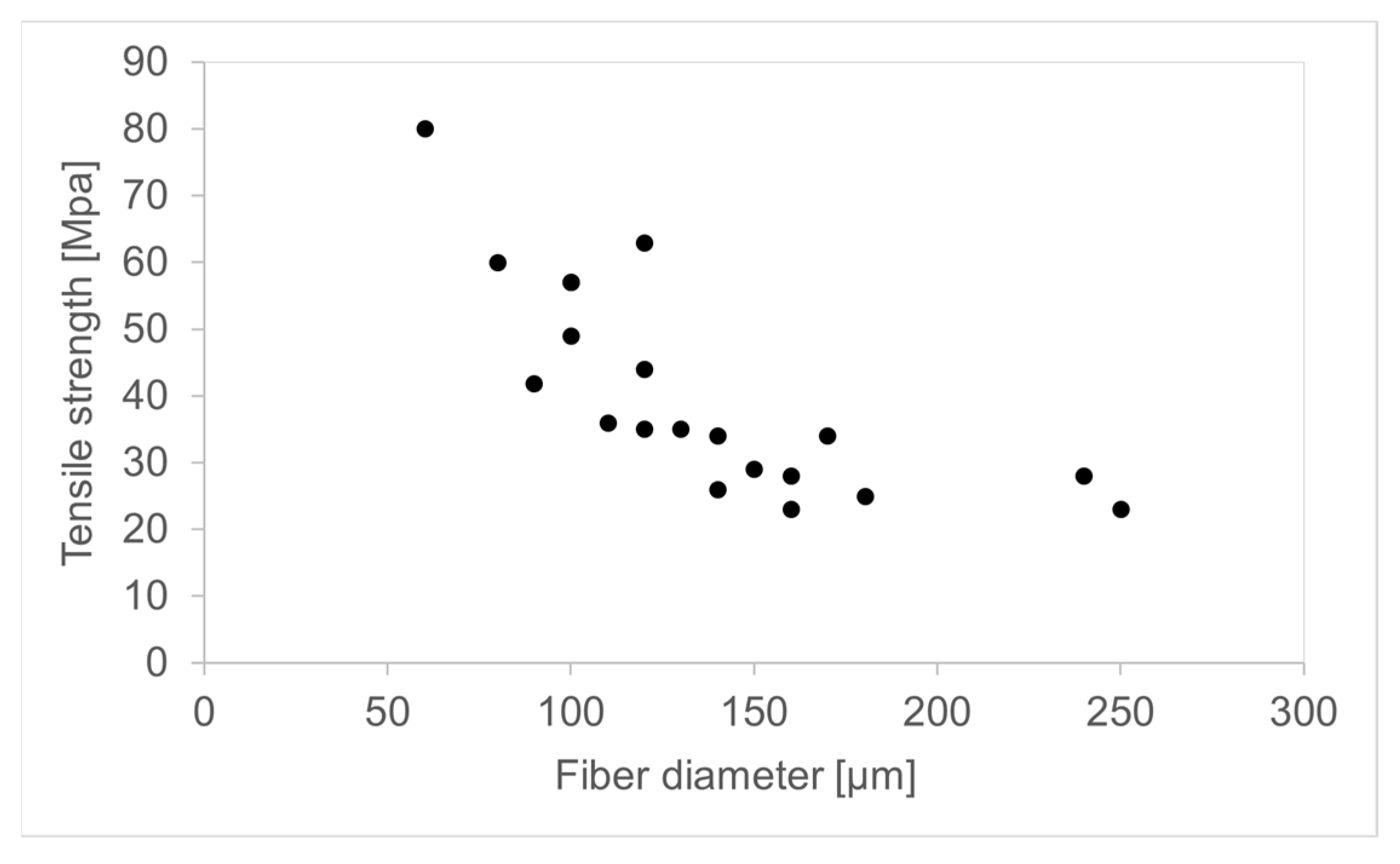
3.2. Preliminary Tensile Strength Tests

Fibers produced from samples C6 and C8 were mechanically tested to draw a first approximate estimate of their tensile strength.
The experimental tensile test was carried out on 20 fibers about 20 cm long, carefully selected for their good uniformity of thickness; the measurement was performed by fixing one of the fiber ends to a sample holder and applying an increasing weight to the opposite one. The tensile strength of each fiber (in megapascals) was determined by measuring the weight (in newtons) necessary to break the fiber and dividing it by the area of the fiber’s cross-section (in square millimeters). The results are shown in Figure 12.
The acquired results are much lower than those expected from commercial basaltic fibers or from reinforcement glass fibers in general [27] and are much closer to the tensile strength performances of standard glass articles (e.g., annealed flat glass under bending stress, bottles under hydrostatic bursting pressure).
It is crucial to outline that the results thus obtained are strongly affected by the defects produced on the surfaces of the fibers by the not-optimized laboratory process exploited for their drawing. In particular, the impossibility of applying a protective sizing to the fibers in the testing rig before their contact with the drawing rollers and with other fibers (as is commonly done in industrial-scale production) led to relevant mechanical damage (scratches and cracks) of their surfaces.
Therefore, the experimental results reported above represent a drastic underestimate of the performance the fibers will be able to reach once their production process is upscaled, optimized and industrialized.

4. Conclusions

This study demonstrated the physical–chemical and technical feasibility of exploiting EAF granulated slag to produce continuous glass fibers with a basaltic-like composition.
The process could employ, as additives, other by-product materials, such as silica fume, feldspars and clays, minimizing the primary raw materials required for fiber production.
Using a custom-made, in-house built fiber drawing testing rig, we produced at the laboratory scale fibers up to 5–6 m long, with a diameter between 60 and 180 µm. The process involved using a small crucible in refractory material with a calibrated diameter bottom orifice, with the function of single nozzle bushing. The optimal temperature range for fiber forming operations in laboratory testing rig conditions was found to be between 1115 and 1125 °C, with a linear drawing speed of about 2 m/s.
Further research and laboratory testing must be carried out to assess the maximum EAF slag percentage that can be added to the basalt-like glass formulation without incurring devitrification or other issues potentially disruptive for fiber production. Moreover, the primary raw material additives preliminarily used in this study, namely sodium carbonate, calcium carbonate and meta-kaolinite, could be substituted with other industrial by-products to render the process fully integrated into the circular economic paradigm.
The optimization of the final chemical composition of basaltic glass on the one hand and the development of the formulation of the vitrifiable mixture of secondary raw materials on the other are, however, tightly connected to the specific melting and industrial fiber forming technology adopted.
Finally, having demonstrated the possibility of obtaining continuous basalt-like glass fibers from granulated EAF slag, we can foresee that another industrial opportunity to “close the recycling loop” might arise from less technically challenging processes, such as the production of noncontinuous fibers for mechanical reinforcement or the production of nonwoven felts and mats for thermal–acoustic insulation (e.g., akin to rock wool and glass wool). Indeed, the production of these materials would be technically and technologically less complicated, and there would be no requirements for high mechanical strength.

Author Contributions

Conceptualization, S.T., S.S., M.P., M.Z. and L.E.D.; formal analysis, S.T., S.S., M.P. and E.B.; funding acquisition, M.Z. and L.E.D.; investigation, S.T., S.S., M.P., E.B. and A.Z.; methodology, S.T., S.S., M.P., E.B., A.Z. and L.E.D.; supervision, M.Z. and L.E.D.; writing—original draft, L.E.D.; writing—review and editing, S.T., S.S., M.P., M.Z., E.B., A.Z. and L.E.D. All authors have read and agreed to the published version of the manuscript.

Funding

This research was funded by Regione Lombardia-Cariplo Foundation 19037, 18-12-2018 on B.U.R.L. No. 52, 27-12-2018, grant No. 2018-1733, project “Development of novel slag-based glass ceramic for plasma spray coating and 3D printing–3D SLAG”, CUP E83D18000240009.

Institutional Review Board Statement

Not applicable.

Informed Consent Statement

Not applicable.

Data Availability Statement

The data are in the references.

Acknowledgments

We acknowledge Metalleghe s.p.a. for kindly providing the silica fume materials.

Conflicts of Interest

The authors have no affiliations with or involvement in any organization or entity with any financial interest or nonfinancial interest in the subject matter or materials discussed in this manuscript.

References

  1. Korhonen, J.; Honkasalo, A.; Seppälä, J. Circular Economy: The Concept and Its Limitations. Ecol. Econ. 2018, 143, 37–46. [Google Scholar] [CrossRef]
  2. Sapsford, D.; Cleall, P.; Harbottle, M. In Situ Resource Recovery from Waste Repositories: Exploring the Potential for Mobilization and Capture of Metals from Anthropogenic Ores. J. Sustain. Metall. 2016, 3, 375–392. [Google Scholar] [CrossRef] [Green Version]
  3. Skaf, M.; Manso, J.M.; Aragón, Á.; Fuente-Alonso, J.A.; Ortega-López, V. EAF Slag in Asphalt Mixes: A Brief Review of Its Possible Re-Use. Resour. Conserv. Recycl. 2017, 120, 176–185. [Google Scholar] [CrossRef]
  4. Jiang, Y.; Ling, T.-C.; Shi, C.; Pan, S.-Y. Characteristics of Steel Slags and Their Use in Cement and Concrete—A Review. Resour. Conserv. Recycl. 2018, 136, 187–197. [Google Scholar] [CrossRef]
  5. Teo, P.T.; Zakaria, S.K.; Salleh, S.Z.; Taib, M.A.A.; Mohd Sharif, N.; Abu Seman, A.; Mohamed, J.J.; Yusoff, M.; Yusoff, A.H.; Mohamad, M.; et al. Assessment of Electric Arc Furnace (EAF) Steel Slag Waste’s Recycling Options into Value Added Green Products: A Review. Metals 2020, 10, 1347. [Google Scholar] [CrossRef]
  6. Brand, A.S.; Fanijo, E.O. A Review of the Influence of Steel Furnace Slag Type on the Properties of Cementitious Composites. Appl. Sci. 2020, 10, 8210. [Google Scholar] [CrossRef]
  7. Wang, Z.; Sohn, I. A Review on Reclamation and Reutilization of Ironmaking and Steelmaking Slags. J. Sustain. Metall. 2019, 5, 127–140. [Google Scholar] [CrossRef]
  8. Hamuyuni, J.; Halli, P.; Tesfaye, F.; Leikola, M. A Sustainable Methodology for Recycling Electric Arc Furnace Dust. In TMS Annual Meeting & Exhibition; Springer: Berlin/Heidelberg, Germany, 2018. [Google Scholar]
  9. Wang, C.; Neelameggham, N.R.; Wang, T. Energy Technology 2018; Springer: Berlin/Heidelberg, Germany, 2018; ISBN 9783319723617. [Google Scholar]
  10. Bianco, L.; Porisiensi, S.; Baracchini, G.; Battigelli, L.; Ceschia, C. Circular Economy in EAF Process: How to Make It Sustainable with Zero Waste Project in Ferriere Nord. Univers. J. Manag. 2018, 6, 190–197. [Google Scholar] [CrossRef]
  11. COM(2013)407-Action Plan for a Competitive and Sustainable Steel Industry in Europe-EU Monitor. Available online: https://www.eumonitor.eu/9353000/1/j9tvgajcor7dxyk_j9vvik7m1c3gyxp/vjafrv3aw3xi (accessed on 27 January 2022).
  12. Wang, P.; Kara, S.; Hauschild, M.Z. Role of Manufacturing towards Achieving Circular Economy: The Steel Case. CIRP Ann. 2018, 67, 21–24. [Google Scholar] [CrossRef]
  13. Zhang, J.; Matsuura, H.; Tsukihashi, F. Processes for Recycling. Treatise Process Metall. 2014, 3, 1507–1561. [Google Scholar] [CrossRef]
  14. Uz, V.E.; Saltan, M.; Tutumluer, E. Transportation Geotechnics Technical and Environmental Evaluation of Metallurgical Slags as Aggregate for Sustainable Pavement Layer Applications. Transp. Geotech. 2020, 14, 61–69. [Google Scholar] [CrossRef]
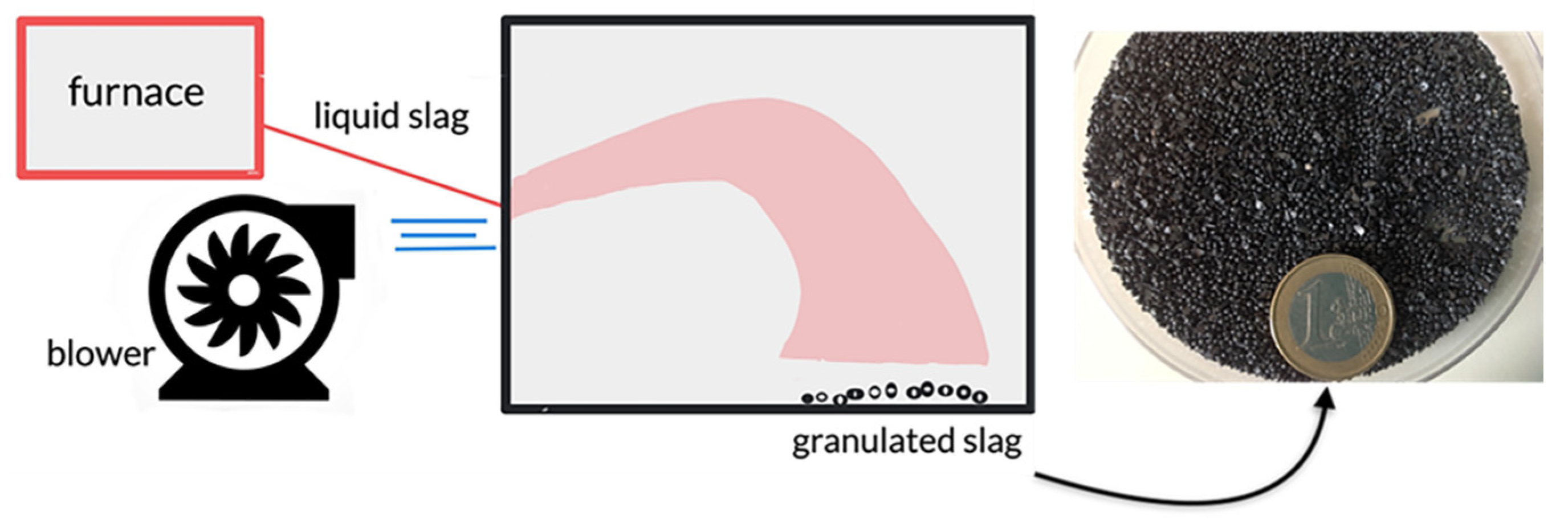
  15. Gao, J.; Feng, Y.; Feng, D.; Zhang, X. Granulation Performance by Hybrid Centrifugal-Air Blast Technique for Treatment of Liquid Slag. Undefined 2021, 392, 204–211. [Google Scholar] [CrossRef]
  16. Roy, S.; Miura, T.; Nakamura, H.; Yamamoto, Y. Investigation on Material Stability of Spherical Shaped EAF Slag Fine Aggregate Concrete for Pavement during Thermal Change. Constr. Build. Mater. 2019, 215, 862–874. [Google Scholar] [CrossRef]
  17. Roy, S.; Miura, T.; Nakamura, H.; Yamamoto, Y. Investigation on Applicability of Spherical Shaped EAF Slag Fine Aggregate in Pavement Concrete-Fundamental and Durability Properties. Constr. Build. Mater. 2018, 192, 555–568. [Google Scholar] [CrossRef]
  18. Gillespie, M.; Styles, M. BGS Rock Classification Scheme, Volume 1. Classification of Igneous Rocks; British Geological Survey: Nottingham, UK, 1999. [Google Scholar]
  19. Seydibeyoğlu, M.Ö.; Mohanty, A.K.; Misra, M. Fiber Technology for Fiber-Reinforced Composites; Woodhead Publishing: Delhi, India, 2017; ISBN 9780081009932. [Google Scholar]
  20. Deng, H.; Wei, X.; Wang, C.; Yang, J.; Li, Z. Effects of cryogenic treatment and interface modifications of basalt fibre on the mechanical properties of hybrid fibre-reinforced composites. e-Polymers 2021, 21, 625–635. [Google Scholar] [CrossRef]
  21. Dhand, V.; Mittal, G.; Rhee, K.Y.; Park, S.J.; Hui, D. A Short Review on Basalt Fiber Reinforced Polymer Composites. Compos. Part B Eng. 2015, 73, 166–180. [Google Scholar] [CrossRef]
  22. Mao, H.; Hillert, M.; Selleby, M.; Sundman, B. Thermodynamic Assessment of the CaO-Al2O3-SiO2 System. J. Am. Ceram. Soc. 2006, 89, 298–308. [Google Scholar] [CrossRef] [Green Version]
  23. Gutnikov, S.I.; Zhukovskaya, E.S.; Popov, S.S.; Lazoryak, B.I. Correlation of the Chemical Composition, Structure and Mechanical Properties of Basalt Continuous Fibers. AIMS Mater. Sci. 2019, 6, 806–820. [Google Scholar] [CrossRef]
  24. Alves, J.O.; Espinosa, D.C.R.; Tenório, J.A.S. Recovery of Steelmaking Slag and Granite Waste in the Production of Rock Wool. Mater. Res. 2015, 18, 204–211. [Google Scholar] [CrossRef] [Green Version]
  25. Fiore, V.; Scalici, T.; Di Bella, G.; Valenza, A. A Review on Basalt Fibre and Its Composites. Compos. Part B Eng. 2015, 74, 74–94. [Google Scholar] [CrossRef]
  26. Vikas, G.; Sudheer, M. A Review on Properties of Basalt Fiber Reinforced Polymer Composites. Am. J. Mater. Sci. 2017, 7, 156–165. [Google Scholar] [CrossRef]
  27. Deák, T.; Czigány, T. Chemical Composition and Mechanical Properties of Basalt and Glass Fibers: A Comparison. Text. Res. J. 2009, 79, 645–651. [Google Scholar] [CrossRef]
Figure 1. Simplified production of granulated slag.
Crystals 12 00359 g001
Figure 2. Phase diagram of CaOeq-SiO2-Al2O3 system. CaOeq = TiO2 + FeO + Fe2O3 + CaO + MgO + Na2O. EAF slag compositions are from [5] and basalt fiber compositions are from [23]. The compositions of the samples are indicated with red stars. The large spot indicates the composition of the EAF slag used in this work.
Crystals 12 00359 g002
Figure 3. Diagram of basalt fiber spinning: (1) crushed stone silo, (2) loading station, (3) transport system, (4) batch charging station, (5) initial melt zone, (6) secondary controlled heat zone, (7) filament forming, (8) sizing applicator, (9) strand formation, (10) fiber tensioning, (11) winding. Reproduced with permission from [25].
Crystals 12 00359 g003
Figure 4. Optical (a) and SEM (b,c) images of the EAF slag spheres. (d) SEM images of the FIB cross-section.
Crystals 12 00359 g004
Figure 5. XRD pattern of EAF slag.
Crystals 12 00359 g005
Figure 6. Images of sample C1 (a) and crucible (b) after melting and solidification.
Crystals 12 00359 g006
Figure 7. XRD pattern of C1 sample.
Crystals 12 00359 g007
Figure 8. Images of samples C2 (a) and C3 (b).
Crystals 12 00359 g008
Figure 9. Images of glass drops (a) and melt flowing down from crucible hole (b).
Crystals 12 00359 g009
Figure 10. Images of sample C7, not annealed (a), and sample C8 annealed at 580 °C for one hour (b).
Crystals 12 00359 g010
Figure 11. Image of the fibers and the fiber XRD pattern.
Crystals 12 00359 g011
Figure 12. Plot of the tensile strength against the fiber diameter.
Crystals 12 00359 g012
Table 1. Sample compositions.
Basalt RockEAF SlagSilica FumeSample C1Sample C2-3Sample C4Sample C5Sample C6-7-8
SiO252.8010.6091.4152.4451.3855.7446.6346.55
FeO310.3043.290.1021.7017.378.7211.3311.29
CaO8.5922.050.1911.128.9211.1412.849.80
MgO4.638.460.854.673.828.812.512.51
MnO0.166.210.043.122.501.261.631.63
Al2O317.505.390.182.792.251.1810.591.66
Cr2O30.062.740.001.371.100.550.710.71
K2O1.460.002.541.311.311.490.920.92
Na2O3.340.091.440.7910.7810.8612.5915.54
P2O50.280.310.220.270.240.190.160.16
TiO21.380.290.000.150.120.060.080.08
Publisher’s Note: MDPI stays neutral with regard to jurisdictional claims in published maps and institutional affiliations.

