
Mechanism of Overlying Strata Structure Instability during Mining below Unconsolidated Confined Aquifer and Disaster Prevention


1
State Key Laboratory of Coal Resources and Safe Mining, China University of Mining and Technology, Xuzhou 221116, China
2
School of Mines, China University of Mining and Technology, Xuzhou 221116, China
3
School of Safety Science and Engineering, Henan Polytechnic University, Jiaozuo 454003, China
4
Qidong Coal Ming, Anhui Hengyuan Coal-Electricity Group Co Ltd., Suzhou 234115, China
*
Author to whom correspondence should be addressed.
Appl. Sci. 2021, 11(4), 1778; https://doi.org/10.3390/app11041778
Submission received: 1 February 2021
/
Revised: 11 February 2021
/
Accepted: 15 February 2021
/
Published: 17 February 2021
(This article belongs to the Section Earth Sciences)
Abstract
:There is a layer of the unconsolidated confined aquifer (UCA) made of non-cemented sand and grit on the bed of Quaternary thick topsoil in many coal mines in east and north China. Existing on the bedrock of coal measures, it poses a serious threat to coal mine safety. Worse, it caused many supports crushing and water inrush disasters (SCWIDs) and resulted in significant economic losses. Aiming at the above problems, this paper adopts a simulation experiment, field measurement, engineering detection, and theoretical analysis to conduct the research. The research reveals the overburden’s destructive rules during mining under UCA. The results indicate that UCA plays an important role in the process of load transfer due to its mobility and replenishment in time. When mining close to the aquifer, the load transfer of aquifer leads to overburden breaking entirely and sliding instability of the bond-beam structure, then, the water flowing fractured zone develops rapidly and connects the aquifer, which is the fundamental reason for SCWID under the UCA. Based on the mechanism of SCWID, a prediction method of support crushing and water inrush hazard zones was put forward. Artificial pre-split blasting based on the location of a key stratum was applied to prevent SCWID. The proposed methods have been used in 7131 working face and safe mining was achieved.
1. Introduction
Mining under a water body is a special coal mining condition in China [1]. In northern and eastern China, the bed rock is commonly covered by very thick alluvium with thickness of about 400 m. A kind of confined aquifer with 3-4 MPa water pressure and containing non-cemented sand and grit exists at the bottom of the thick alluvium. To prevent roof water flooding accidents when mining near the confined aquifer, coal mines were required to set safety pillars for isolating normal fracture zone from aquifer before underground mining [2]. Theoretically, mining below this aquifer is safe and the water from the aquifer could not rush into the working face. However, when mining under the aquifer, many water inrush disasters occurred, together with supports crushing disasters, called supports crushing and water inrush disasters (SCWIDs). This seriously restricts the safety and high efficiency of coal mining. These disasters not only caused significant economic cost, but also affected the normal mining scheduling and influenced the production situation [3,4,5].
After coal seam mining, the overburden is usually divided into the caving zone, the fracture zone, and the bending zone according to the different fracture states [6,7,8,9,10]. Among them, the caving zone has a high degree of fracture development, disordered fracture distribution, and strong permeability, while there are mainly horizontal fractures and interconnected vertical fractures in the fracture zone. Water source and water inrush passage are the necessary conditions for mine water inrush. Water flowing fracture is one of the main and common passages in the coal mine. Figuring out the evolution law of water flowing fracture is the foundation to reveal the mechanism of water inrush disasters. When interconnected vertical fractures directly develop into the aquifer, the coal mining faces suffer the threat of water inrush. Water inrush disasters usually are generally considered to be a problem in the domain of hydrogeology. Such water inrush presents many concerns for miners and researchers [11,12,13,14,15,16].
For the problems of SCWIDs under the unconsolidated confined aquifer (UCA), previous studies mainly focused on the set of waterproof coal pillars. Liu studied different types of UCA and their influences on leaving the safe coal pillar and proposed a new optimization method for coal pillar outcrops based on the variation rules of overburden’s “two belts” growth altitude in the close unconsolidated aquifer [17]. According to the borehole results, Kang attributes the disasters to geological factors such as fault, primary fractures, and so on [18]. However, the periodical disasters cannot be well explained, and it is hard to give a reasonable explanation for why the actual water flowing fracture breaks through the usual height. Wang analyzed the characteristic of UCA and described the difference of aquifer characteristics and its impact on rock breaking, but the mechanism of the SCWIDs was not well revealed [19]. Chen provided prediction results of water inrush areas based on GIS and analytic hierarchy process under UCA in the Qidong coal mine [20]. Yang stated that the main reason for the disasters lies in the decrease of the bottom interface, which causes a shortage of waterproof coal pillar. They also proposed prevention measures of grouting and plugging, dewatering, and depressurizing [21]. Wang and Xu studied the relationship between water level variation of unconsolidated confined aquifer and roof weighting and put forward a method for warning of water inrush accidents, and then analyzed the water inrush mechanism [22,23].
In addition, it is so strange that supports crushing disaster happened in the event of a water inrush disaster. In the traditional view, supports crushing is usually due to the abnormal appearance of underground mine pressure, which is a problem closely related to mining engineering. Regarding the supports crushing disaster, Xu analyzed the structure type and breakage and unbalance characteristics of overburden key strata, pointing out supports crushing types in the longwall mining of shallow seams, then studied the prevention and control technology of large area powered support jammed and roof falling accidents which occurred in the coal mining face [24]. Ju put forward prevention measures for support crushing when mining out the upper coal pillar in close distance shallow seams, but no research connected it to the relevant knowledge of hydrogeology [25]. Kuang found that the primary key stratum of the overlying strata is the main controlling stratum and its fracture and movement are the root cause of strong ground pressure behaviors, such as rib spalling, roof fall, and support crushing. Other researchers suggested that hydraulic fracturing, deep hole blasting can be used to relieve ground pressure behavior [26].
The above studies mainly analyzed such a complex problem from a single point of view, either from hydrogeology or mining engineering. Therefore, the special occurrence mechanism (in relation to both hydrogeology and mining engineering) and the reasons for overburden failure have not been revealed. Furthermore, the disasters prevention methods should also be implemented based on the mechanism of overlying strata structure instability under this geological condition. In this paper, the cases will be first analyzed. Then, under certain simplified conditions, the occurrence mechanism of overlying strata structure instability during mining below unconsolidated confined aquifer is further studied through physical simulation and theoretical analysis. Based on the occurrence mechanism, prevention and control methods of SCWIDs are proposed and have been applied in engineering.
2. Cases of SCWIDs
2.1. Summary of Incomplete Statistics of Cases
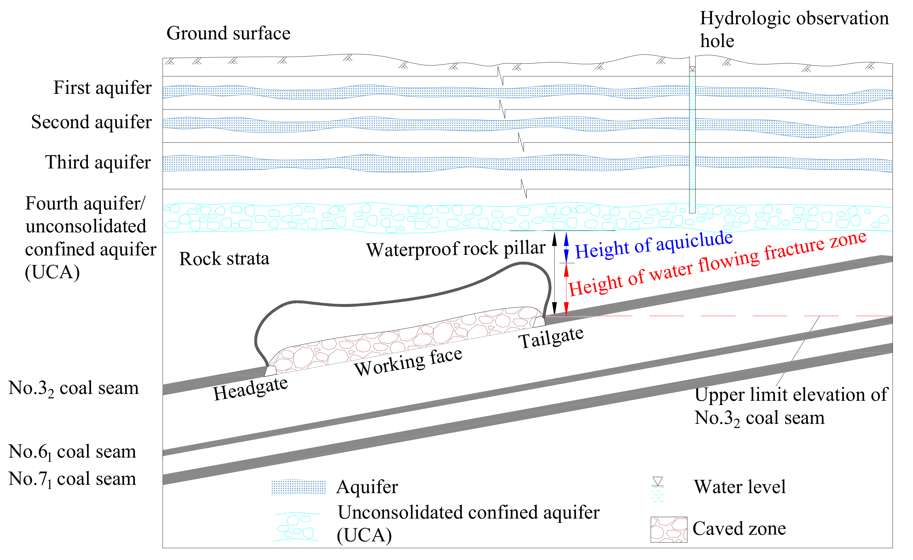
In Northern Anhui province, there is an unconsolidated confined aquifer at the bottom of the thick unconsolidated layer in many coal mines. Because it belongs to the fourth aquifer from shallow to deep, it is called "fourth aquifer" for short. When mining adjacent to "fourth aquifer", it is necessary to reserve waterproof coal/rock pillar/layer according to the requirements of national regulations, and the thickness (height) is generally the sum of the height of water flowing fractured zone and the thickness of the protective layer (see Figure 1). However, in the actual mining process of working face, many water inrush accidents occurred. For example, Qidong coal mine had 16 water inrush accidents in 3222 working face, 7114 working face and other 5 working faces from 2001 to 2010, which caused 402 supports crushed, and the most serious water inrush in 3222 working face reached 1520 m3/h, resulting in mine flooding accidents, threatening safety in production and resulting in huge economic losses.
Statistical results (Table 1) show that in the design of all the working faces with water inrush and support crushing, sufficient thickness of waterproof coal and rock pillars were reserved according to the national standard requirements, but the abnormal water inrush and support crushing still occurred. In addition, the statistical results also show that the water inrush accidents occurred in the mining process of No.32, 61 and 71 coal seams in Qidong coal mine, including 3 times in No.32 coal seam, 4 times in No.61 coal seam, and 9 times in No.71 coal seam. The width of the working face with accidents is about 150 m; the mining height is 1.67–3.7 m, mostly about 2.5 m; the rated working resistance of the hydraulic support is generally low, mostly within 6000 kN. The water pressure of the overlying aquifer on the working face is generally large, ranging from 3.2 MPa to 3.9 MPa, and the thickness of the overlying strata is generally small when the water inrush and support crushing happened, most of which are within 100 m. Most of the support crushing accidents occurred in the initial mining stage of the working face, the number of which reaches 47% of the total number of accidents, such as during the initial roof weighting stage, or when the advancing length of the working face was close to the width of the working face. The specific position of the support crushing was mostly located in the middle of the working face, with a total of 10 times; among them, four accidents were serious, with the support crushing occurring in the whole working face; the other two accidents only occurred in the local area of the working face.
2.2. Details of SCWID in Working Face 3222 of Qidong Coal Mine
To further understand the detailed process of SCWID, the accident that occurred in 3222 working face of Qidong coal mine is described below.
3222 working face is the first mining face of Qidong Coal Mine. The starting and ending elevation of the working face is from −420 m to −540 m. The working face is 800 m long and 150 m wide. It is an inclined strip fully mechanized working face. The average thickness of the coal seam is 2.5 m and the average dip angle is 10°. According to China’s standard requirements for mining under water, the height of water flowing fractured zone under medium hard roof was calculated to be about 27.3–38.5 m. The thickness of the protective layer was designed to be 6 times of the thickness of the coal seam. Therefore, the height of waterproof rock strata to be reserved was 42.3–53.5 m. The actual minimum height of waterproof rock strata to be reserved was 63 m, which was about 9.5 m higher than the maximum height required by the theoretical calculation. Theoretically, no water inrush accident should occur. One hundred and ten ZZ4400/17/35 hydraulic supports were installed in the working face, MG250/600-WD1 coal cutter was used for coal mining, and natural caving method was used to manage the roof.
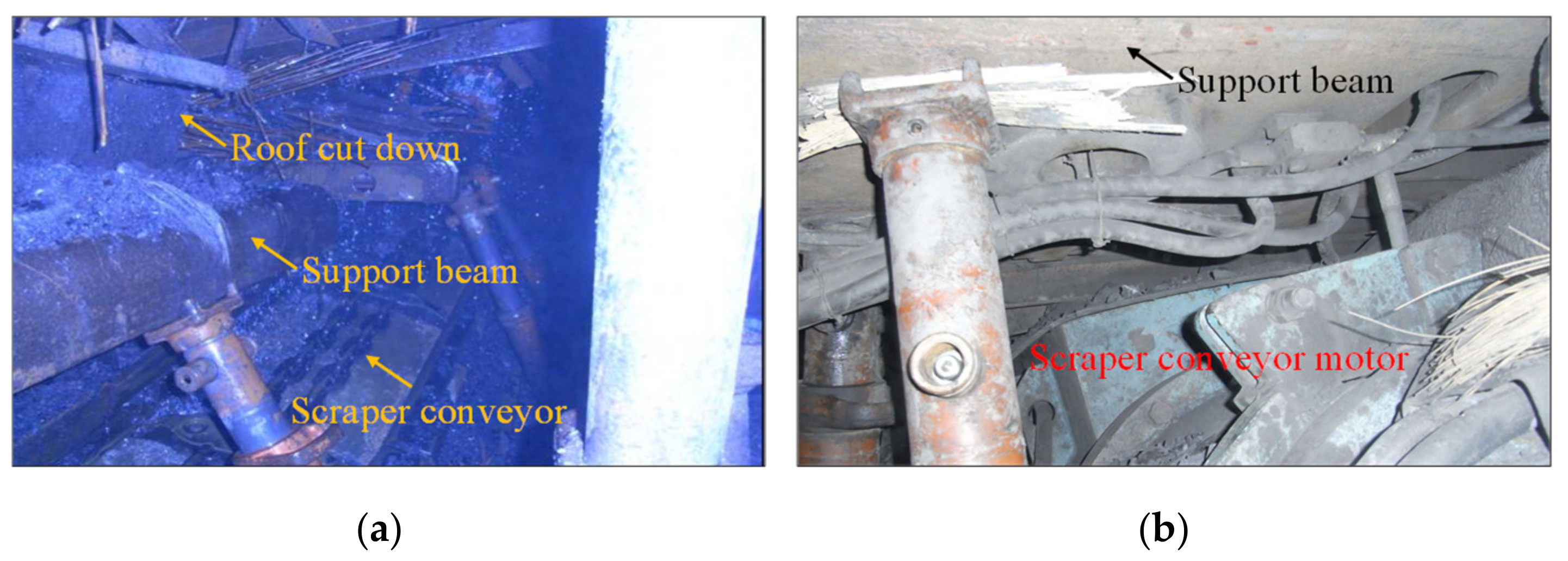
From 5 November 2001 to 10:30 on 18 November 2001, the working face was advanced by 28.8 m; the main roof experienced the first weighting, most of the support safety valves of the working face were opened. The immediate roof caved sufficiently into the goaf, and there was no water dripping phenomenon. Then the working face continued to advance, and no abnormal phenomenon was found. At 4:30 on 24 November, when the working face was advanced by 42 m, the roof underwent the weighting again and fracture, which caused No.50–60 supports to be crushed (see Figure 2); and the roof at the head of the machine appeared to show water seepage. At 5:56, the speed of water seepage at the seepage point increased to 10 m3/h, to 80 m3/h at 8:00, sharply to 1300 m3/h at 11:30, and at 4:20 a.m. on 25 November, the value reached 1520 m3/h and was still increasing. The water level outside the retaining wall reached 1.8 m and rose at the speed of 300 mm/h. The water level of the pump room reached 5.22 m. At this time, the pump room was flooded. Due to the excessive water volume, the increase speed was also fast, and the drainage capacity of the mine was limited. Finally, the mine was flooded. Fortunately, there were no casualties. It took only 24 hours from water seepage in goaf to mine flooding. The water inrush accident seriously affected the normal production of the mine, resulting in economic losses as high as 36.4856 million Yuan. It took one year to repair the mine to resume the normal production.
3. The Occurrence Mechanism of SCWID
3.1. Mechanism of the SCWID
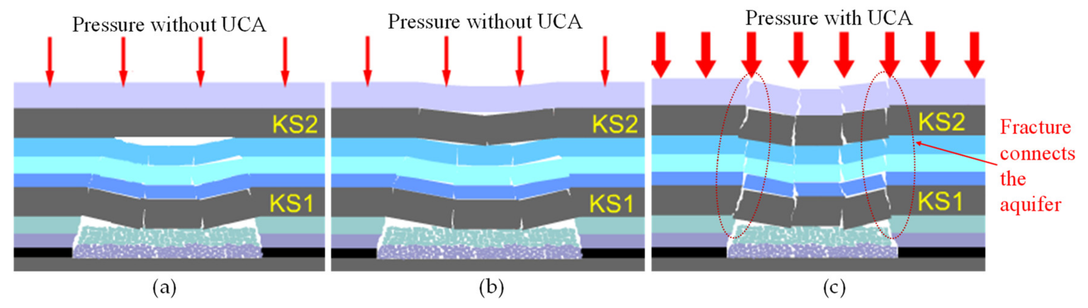
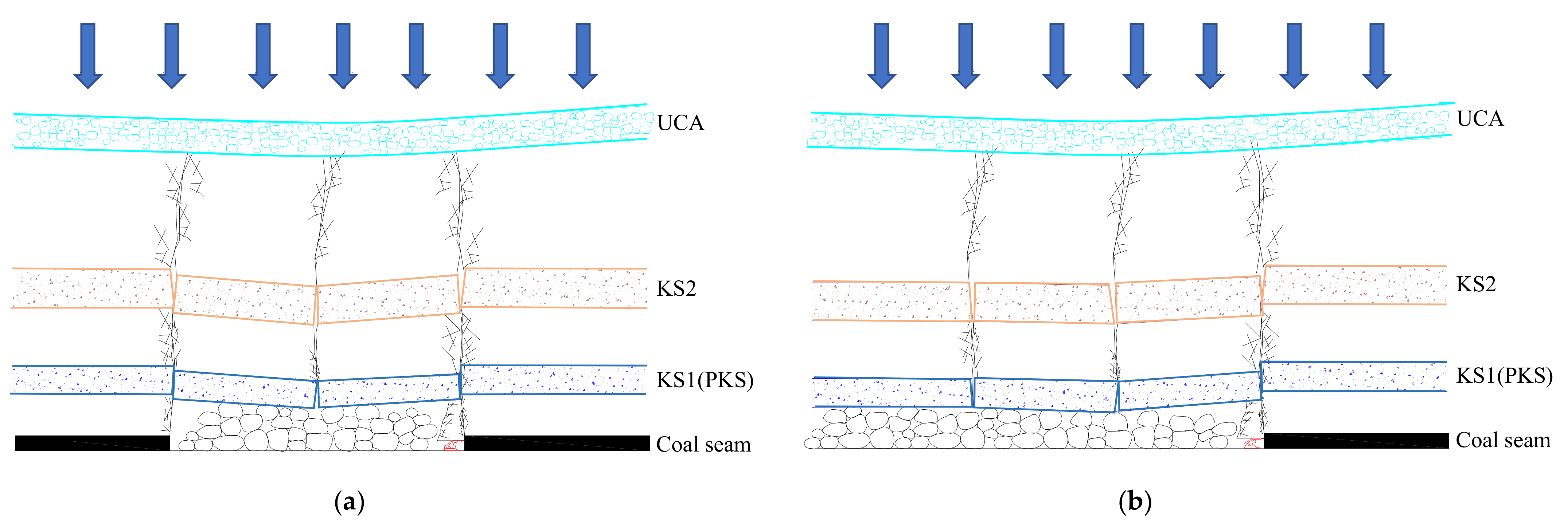
In general, load causes rock breakage mainly comes from the self-weight load and parts load it controlled. As the mining face advances, lower rock breaks first when its dangling length reaches the ultimate failure length. Usually, the load exerted on the bedrock decreases if without the UCA. At the same time, the load transferred to the key stratum (KS) becomes small, which causes KS1 to break before KS2, as shown in Figure 3a. Namely, the lower KS1 breaks first and then the upper KS2 breaks as shown in Figure 3b. The water flowing fracture is not fully developed to connect the aquifer. The overburden structure can maintain its stability. It can be seen that different fractures can determine whether the SCWID occurs or not.
When mining below UCA, the overburden is easier to break entirely when subjected to the aquifer’s load transfer, as shown in Figure 3c. However, the question is why the entire overburden breakage leads to support crushing accidents. This can be explained reasonably by the “sliding-rotation” stability theory of bond-beam structure. Equation 1 is the conditions preventing the bond-beam structure from sliding instability derived by Qian [27].
where h is the thickness of the first key stratum (KS1). h1 refers to the thickness of overlying strata that KS1 supports. σc is the compressive strength of KS1. ρg is the volume force of rock. tanφ is the friction coefficient between rocks, and θ1 is elevation angle of break block in bond-beam structure.
Due to the load transfer of UCA, the topsoil layer is subjected to excessive load, leading all the key strata under certain conditions to break entirely. The upper key stratum and its controlling strata break entirely and become load strata of the lower stratum. The load strata thickness (h1) of the fracture blocks in lower key stratum increases obviously, and bond-beam structure is likely to become unstable. If the support resistance is not enough, support crushing disasters will happen. For instance, if the support resistance is only 5000 kN, the unstable strata height that the supports can bear is usually less than 30 m. However, when mining below the UCA, once the key stratum breaks synchronously, the height of unstable strata is much greater than 30 m. Therefore, support crushing disasters will be unavoidable. On the other hand, with load transfer from the UCA, more than one key stratum breaks synchronously and water flowing fracture in overburden strata connects the aquifer, resulting in the water inrush disaster.
3.2. Verification by Physical Modelling
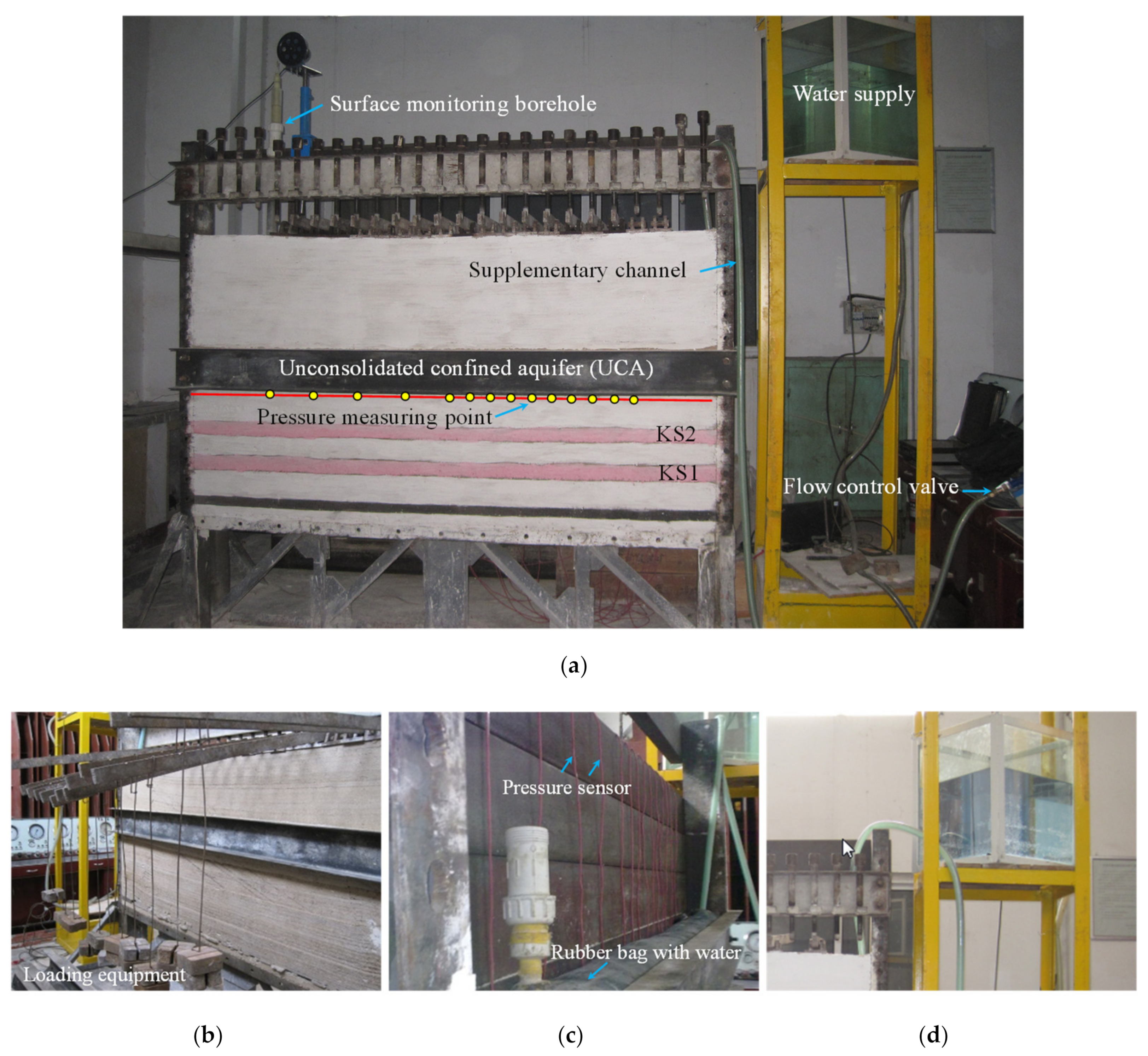
Based on the mechanism illustrated in Section 3.1, the presence of the thick UCA plays an important role in the occurrence of the SCWIDs. To further verify the mechanism illustrated above, a physical experiment system was designed to study the role of an unconsolidated confined aquifer in the process of load transfer, as shown in Figure 4a. Two physical models, either with or without UCA, were considered. In this simulation experiment system, the rubber water belt filled with sand was used to simulate the confined aquifer. The head pressure was provided by a certain height of water tank and the flow control valve was used to simulate the recharge permeability characteristics. Simulation material, 50 cm thick, was laid on the upper part of the water belt to simulate parts of the rock strata, and the top of the model was loaded using the lever principle to simulate the weight/pressure (48 kPa) of the upper remaining rock strata as shown in Figure 4b. The top of the simulation system was equipped with a hydrological observation hole, which was filled with water, and the sensor was used to collect the water head height in the hole. In the process of simulation, with the mining of working face, the pressure at the bottom of the water body and the change of water head height in hydrological monitoring hole were monitored by pressure sensor. The coal seam was mined from the right side of the model to the left side. Fifty centimeters of protective coal pillar was left at the boundary to eliminate the boundary influence.
Compared with the prototype, the model similarity ratios are geometry 1:100, weight 1:1.5, rigidity 1:150, stress 1:150, internal friction angle 1:1, and Poisson’s ratio 1:1. Table 2 shows lithology parameters and mechanical parameters in the experiment. In the preparation of the model, refined silver sand was used as aggregate and the plaster was used as cement. Sheet mica was used between layers. Under the UCA, pressure sensors were installed to record the load distribution. The pressure sensor can be seen in Figure 4c. The water supply can be seen in Figure 4d.
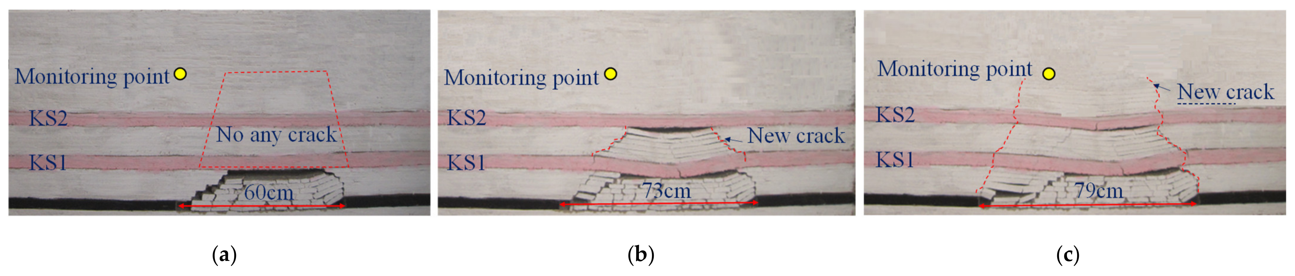
In the simulation experiment, the model started mining from the right side to the left side, leaving a 50-cm-wide boundary pillar on the right side. As shown in the simulation results in Figure 5, without the simulation of UCA water pressure, the coal seam was continuously being mined to the left. When the mining width/distance reached 60 cm, KS1 did not break, and there was no crack in the upper strata of KS1 and KS2. When the mining width reached 73 cm, KS1 was broken. At this time, the strata between KS1 and KS2 also collapsed with the breaking of KS1. At this time, the new fractures were mainly located between KS1 and KS2, and there was no fracture above KS2. The coal seam continued to be mined to the left. When the mining width reached 79 cm, KS2 broke and caused obvious damage to the rock strata at a certain height above KS2. At the same time, the original fracture between KS1 and KS2 developed upward with the breaking of KS2, and a new fracture was formed above KS2. In this experiment, KS1 broke earlier than KS2, and the fracture development degree was obviously affected by the breakage of the KS, indicating a staged development process.
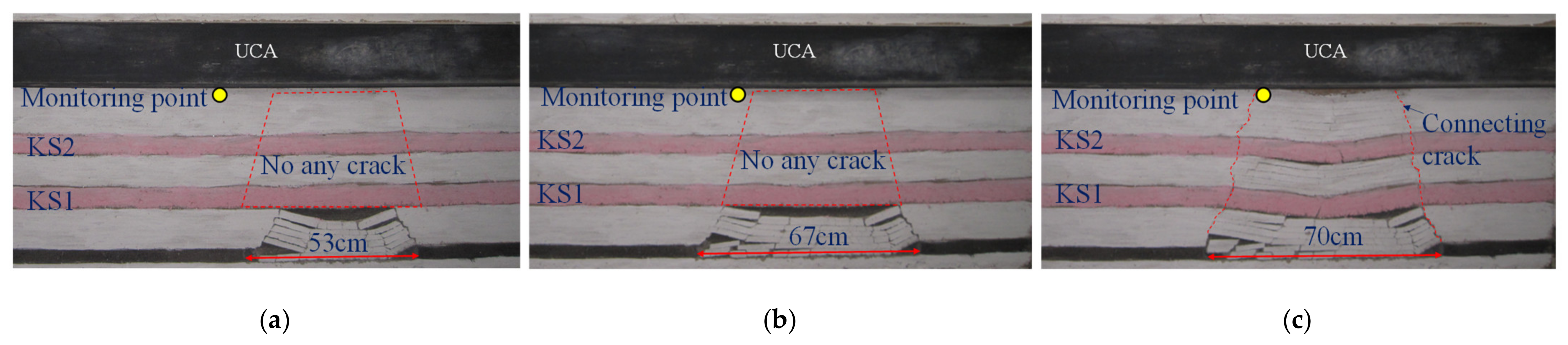
Following the experiment described above (the UCA water pressure was not considered), the simulation experiment considering the presence of UCA was performed, and the simulation results are shown in Figure 6. The results show that when the coal seam was mined 53 cm to the left, there was no damage in KS1 and KS2, and there was no fracture in KS1 and its upper strata. The coal seam continued to be mined to the left. When the mining width reached 67 cm, KS1 and KS2 were still not damaged, and there were no cracks in KS1 and its upper strata. The coal seam continued to be mined to the left. When the mining width reached 70 cm, KS1 and KS2 suddenly broke synchronously under the action of upper pressure. At this time, a large number of fractures were generated between KS1 and KS2, and between KS2 and UCA, and these fractures directly connected the coal seam and the aquifer.
From the comparison of the two tests, it can be seen that the mining width was different when KS1 broke: 73 cm when there was no UCA, and 70 cm (slightly smaller than no UCA case) when there was UCA. This suggests that KS1 is subject to greater load when there is aquifer, thus shortening the breaking distance.
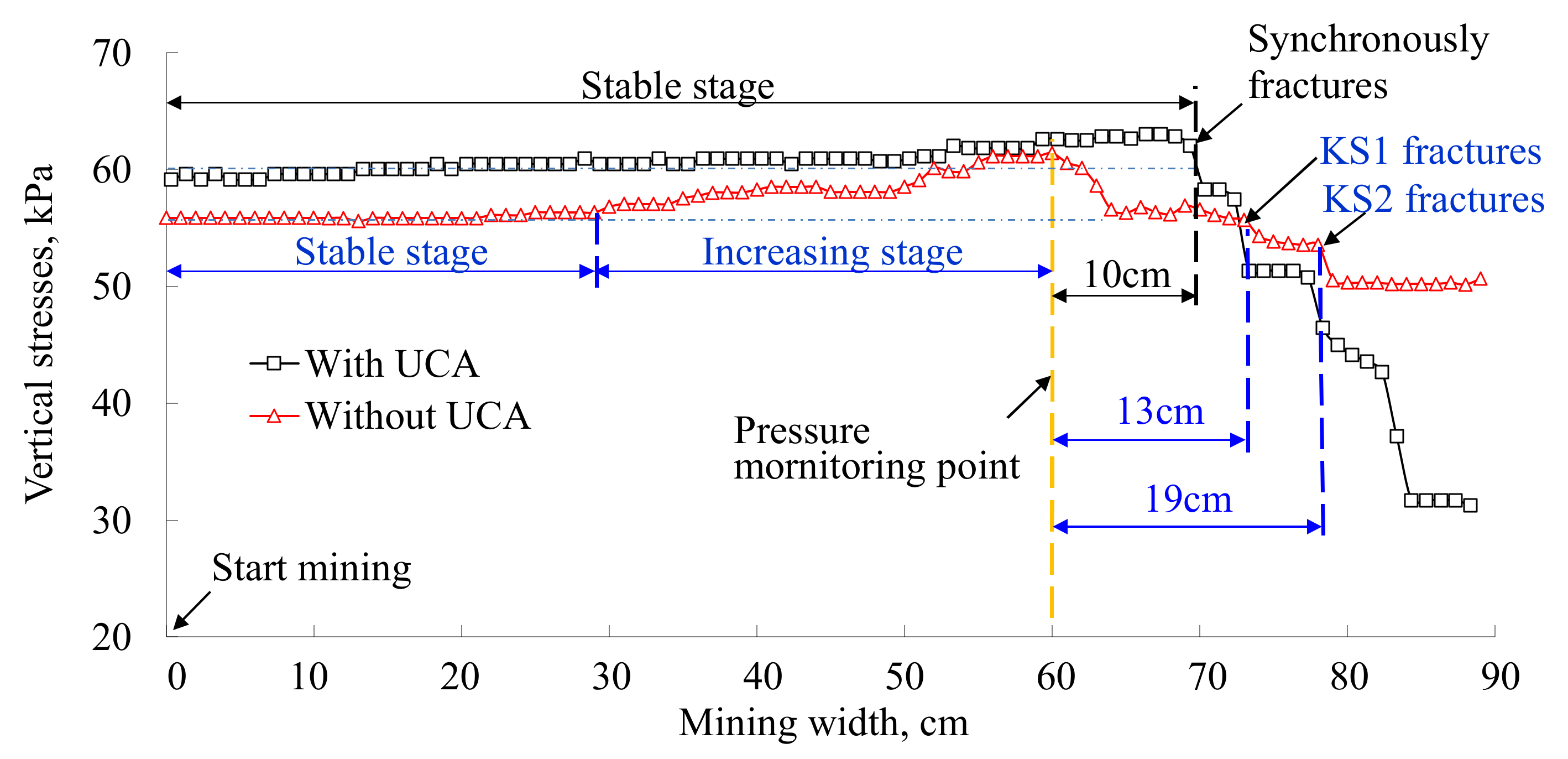
To further analyze the difference of the upper load on the broken strata between the cases with and without aquifer, the pressure data of the same position in the same height from the coal seam are now analyzed. From the simulated results in Figure 7, before the working face passed through the pressure monitoring point, the stress basically remained unchanged with UCA. The pressure has an obvious stable period, which shows that the load has been acting on the key layer, but it showed a continuous upward trend without UCA after stable stage (due to the transfer of the abutment pressure), which shows that when there is UCA, the load is continuously acting on the lower strata (at this stage, the abutment pressure is not transferred to the mining boundary as in the case of no UCA).
When the working face passed through the monitoring point, in the scenario of UCA, before KS1 and KS2 broke, the stress still remained unchanged, but when it continued to advance to 70 cm or passed through the monitoring point 10 cm, KS1 and KS2 broke synchronously, and the stress value decreased quickly. In the scenario of no UCA, the stress of the measuring point decreased immediately after passing through the monitoring point. When the working face advanced about 13 cm through the measuring point and the cumulative advance distance was about 73 cm, KS1 broke first, and KS2 broke when the working face advanced about 19 cm through the measuring point and the cumulative advance distance was about 79 cm. The breaking distances of KS1 and KS2 were greater than those in the situation of UCA, suggesting that the larger the load, the shorter the breaking distance of KS1 and KS2.
The simulation results show that under the condition of UCA and no UCA, the load of the aquifer on the lower strata before breakage is different, which leads to the obvious change of breakage and movement characteristics. The simulation results verify the influence mechanism of aquifer loading on overburden fracture explained in the previous section.
3.3. Engineering Verification of Overburden Breakage’s Features
The mechanism of key stratum broken entirely during mining below UCA can be further verified through the water level variation of long-term hydrology detecting hole and the actual water flowing fractured zone of Qidong coal mine.
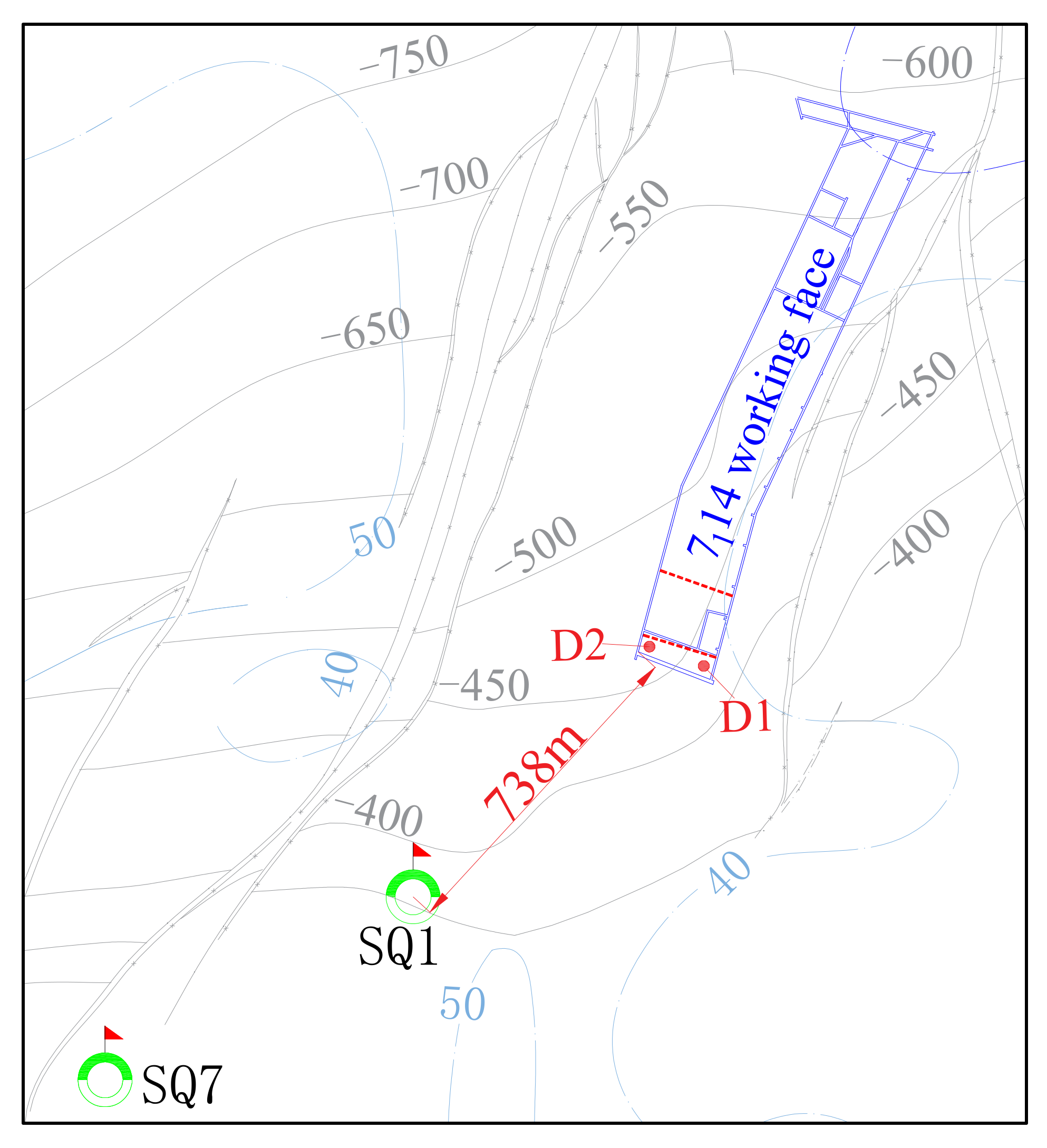
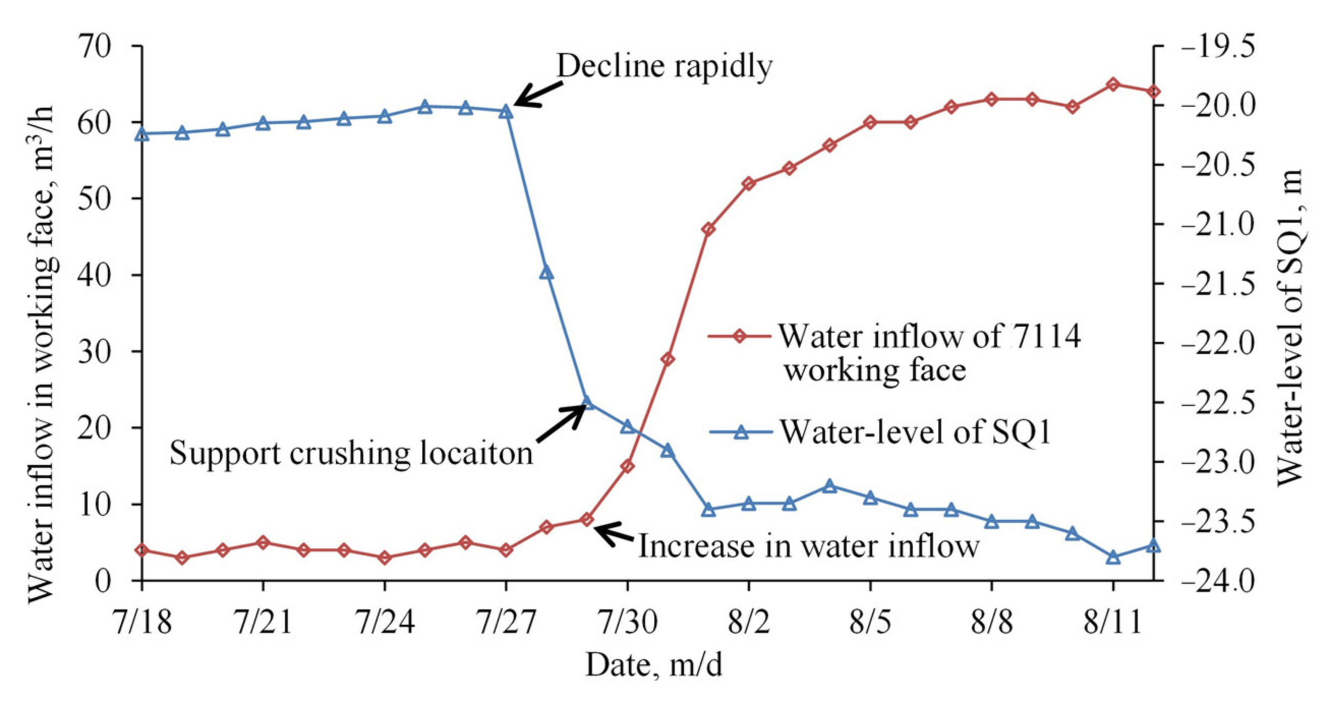
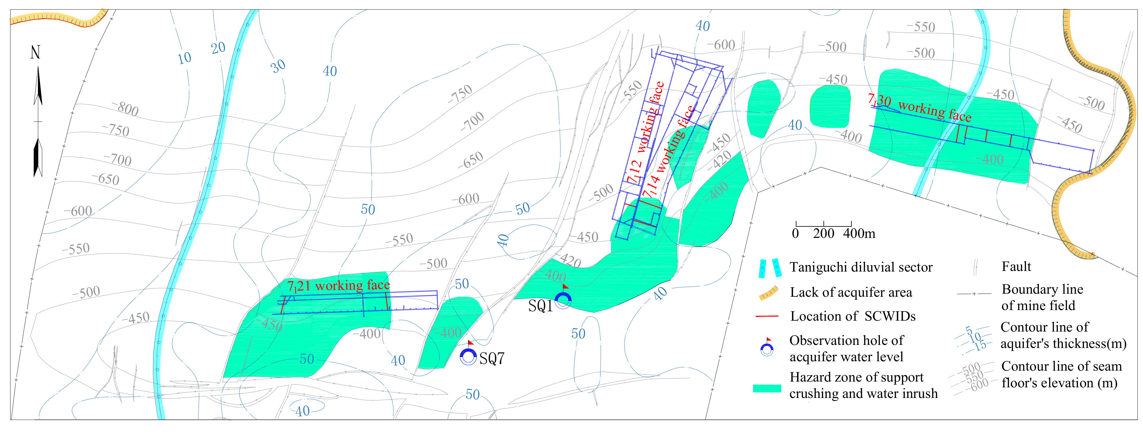
To monitor the water level variation of the aquifer, many long-term observation holes were constructed around the Qidong mine. For example, in 7114 working face, No.SQ1 long-term observation hole is about 738 m away from 7114 working face, as shown in Figure 8, and the water level can be influenced during coal mining. Meanwhile, water inflow at 7114 working face was monitored. The field data show that No.SQ1 long-term hydrology detecting hole kept stable from 7 July 2004 to 27 July 2004, and the water level elevation was about −20.5 m (ground elevation was about +22 m). However, when the SCWID happened on 29 July, the water level elevation decreased rapidly to −23 m, while the water inflow in working face did not increase suddenly, but increased step by step, then reached 60 m3/h and kept stable until 3 August 2004. Figure 9 reveals the correspondence between water inflow of 7114 working face, the water level decline of the aquifer and the supports crushing during coal mining.
Obviously, the rapid decline of water level in No.SQ1 long-term observation hole was not caused by the water inflow in 7114 working face. This is because only when the large-area falling-over of the roof appears, the rapid mobility and recharge of confined water can be caused. From the correspondence between the dynamic change of water level and water inflow variation before and after support crushing in 7114 working face, it can be seen that when support crush disaster happens, the bedrock under UCA breaks entirely. This is consistent with Wang [22], who analyzed and explained the relationship between the change of water level and the change of roof pressure, and believed that the rapid decline of water level was the advanced reflection of rock instability movement.
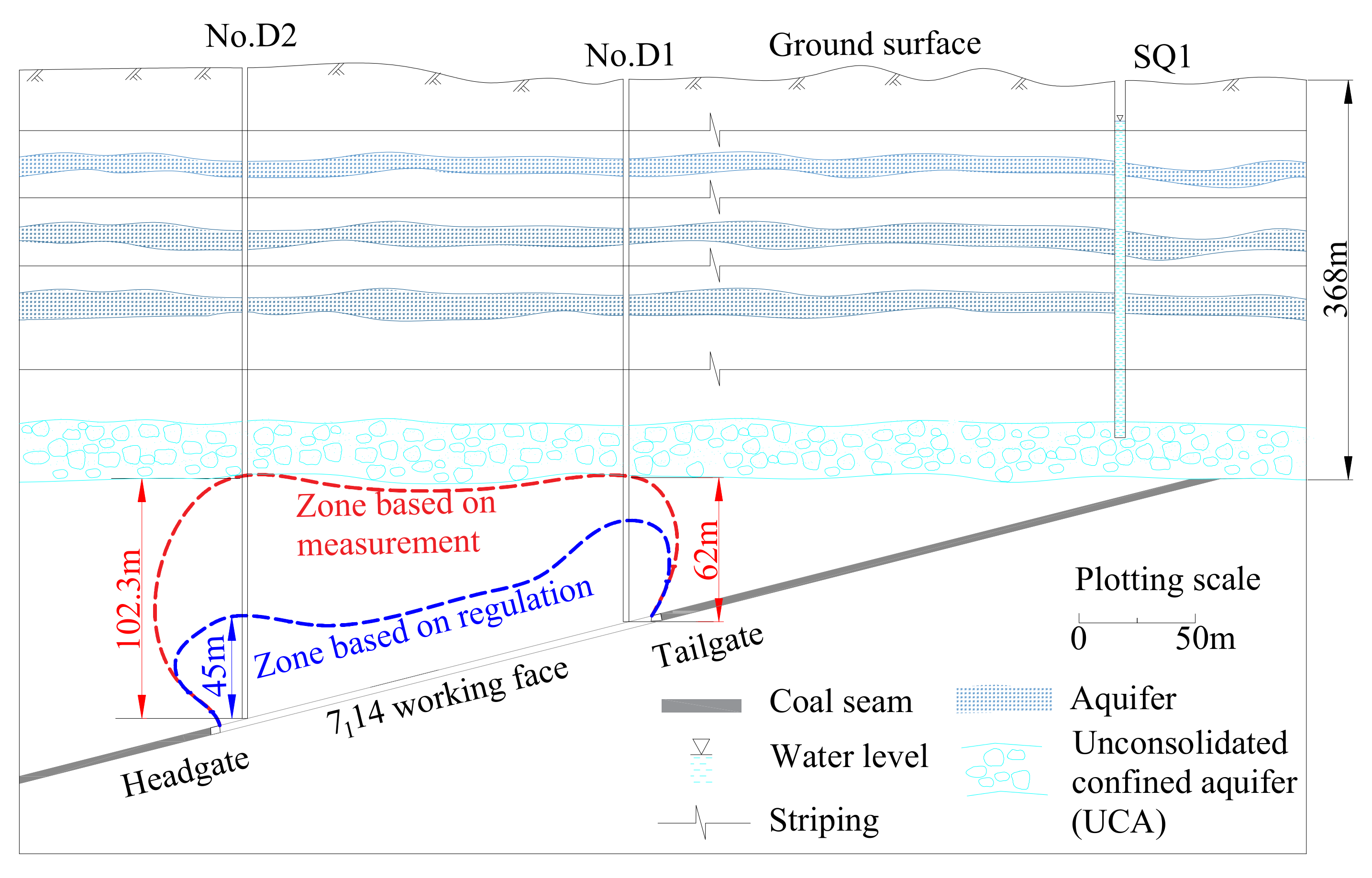
According to the conventional method ([2], pp. 73–78), the maximum height of water flowing fracture is expected to 45 m in medium-hard rock layer, the bed rook thickness is far larger than the theoretical value. Therefore, in theory, water inrush was less likely to happen. Furthermore, in order to find out the actual height of water flowing fissures at the water inrush position of 7114 working face, two ground vertical exploration boreholes were constructed near the water inrush position. D1 drill was 18 m inside the goaf near the ventilating roadway of 7114 working face, D2 drill was 16 m inside the goaf near the haulage roadway. Figure 10 shows the difference between the results. The height of water flowing fracture of D1 and D2 is 62.0 m and 102.3 m respectively [18]. The real detection result is far greater than the estimated value, and eventually the water inrush accidents happen, which indicate that the water flowing fractured zone has developed and connected the aquifer. Meanwhile, the difference of the height of water flowing fracture around the drill location is basically the same as the difference of bedrock thickness, which further shows that when SCWID happen in 7114 working face, the overlying strata broke entirely. The detection results confirmed the mechanism of the SCWID beneath UCA explained above.
4. Prevention Measures and Engineering Practice
4.1. Prediction of the Dangerous Area
The SCWID is likely to happen when the key strata break simultaneously under the influence of load transfer from UCA. Therefore, it is of great significance for the prevention and control of the disasters if the dangerous area of SCWID can be predicted before mining. In this way, the dangerous area can be avoided in the mine design and mining, and some effective measures can be taken in advance to avoid possible disasters. According to the research results of the literature [28], when there is a primary key stratum in the overburden within the range of 10 times of the mining height of the coal seam, it is easy to cause the structural instability of the overlying key strata, resulting in the water inrush and support failure disasters. According to this principle, the dangerous area of water inrush can be analyzed. In literature [23], a similar method was used to judge the dangerous area of No.32 coal seam in Qidong coal mine. However, with the mining of the lower coal seam, it is also necessary to predict the dangerous areas of No.61 and No.71 coal seams. According to previous research [29], in the area of repeated mining, it is considered that because the upper coal seam mining has caused damage to the rock strata, the risk of water inrush and support crushing of working face under the goaf is low. Therefore, this paper mainly studies the risk of water inrush under the initial mining condition of the lower coal seam.
The first step is therefore the identification of the locations of the key strata [27]. Based on the overlying strata breakage rules, the identification method of the key stratum and calculation software can be used to identify the location of key strata and their structural types, thus providing the basis for prediction of dangerous areas.
Take the identification result of three drilling holes of No.71 coal seam as examples, group A in Table 3 shows the single key stratum in No.24–257 drilling hole, the primary key stratum is only 3.42 m from 71 coal seam, which is less than 7–10 times of mining height, water flowing fracture will develop to the UCA when overlying strata breaks entirely. Therefore, it is dangerous when No.71 coal mining near this borehole. In group B of Table 3, No.Caiqian3 borehole shows multilayer key strata, which were located 53.54 m from No.71 coal seam, far more than 7–10 times of the mining height (which is about 19.32–27.6 m). Under the influence of mining, the key stratum breaks step by step from the bottom to the top of bedrock, the height of water flowing fractured zone will be less than 53.45 m and will not develop to the UCA. Therefore, there is no risk of SCWID in No.71 coal mining near this borehole. In group C of Table 3, No.296 borehole has multilayer key strata, but the primary key stratum is only 6.82 m from No.71 coal seam, which is less than 7–10 times of mining height and the water flowing fracture will develop to the UCA. Therefore, the area near No.296 borehole is a dangerous zone of SCWID.
Based on the methods mentioned above, the category of areas (dangerous or not) on plans of mining and designing through the analysis of key strata location and structure types. The predication result of dangerous areas of SCWID at No.71 coal seam in Qidong coal mine was shown in Figure 11. Based on the prediction results, it was found that the water inrush positions of overpressure support in No.71 coal seam are in the danger area, which shows that the prediction method and prediction result are consistent with the actual situation.
4.2. Artificial Pre-Split Blasting
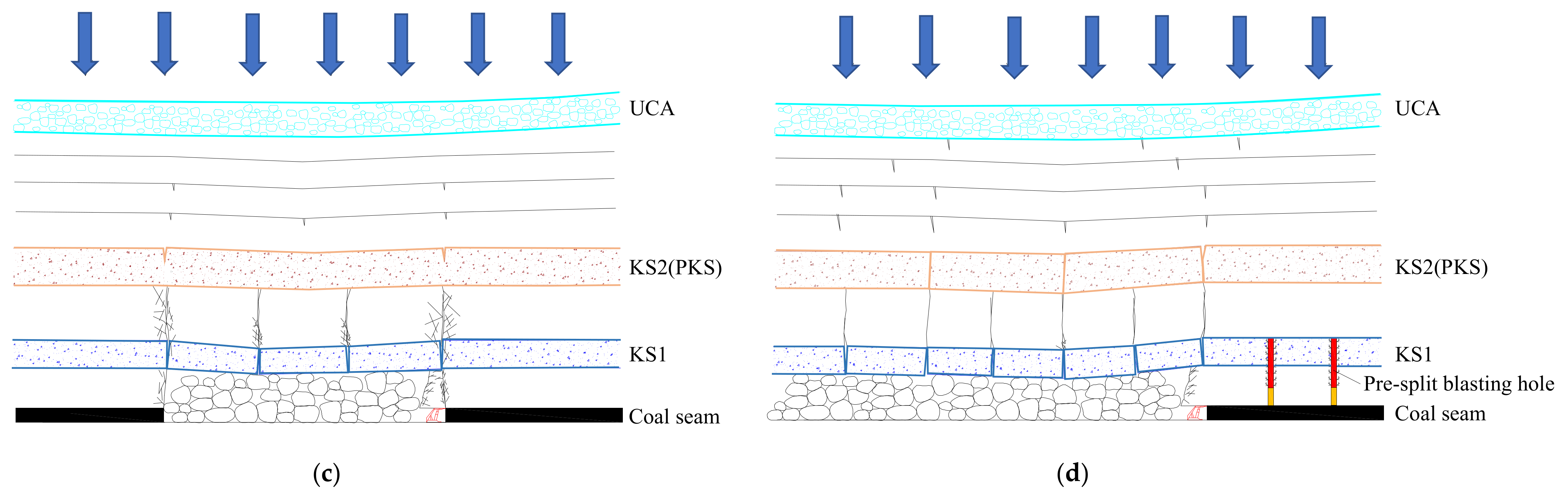
Research on the mechanism of SCWID during mining under the UCA has provided a theoretical basis for the prevention of SCWID. The key to prevent the disaster is to change the breakage characteristics of overlying strata, or to prevent the roof sliding instability by taking necessary measures. On such basis, artificial pre-split blasting is proposed to change the KS structure characteristics of overlying strata, which can be used to change the breakage characteristics of KS structure, and then avoid the SCWID.
For the key stratum (KS) under threat of entire breakage, pre-split blasting can be adopted to weaken the key stratum in the overlying strata within the range of ten times mining height, reduce its strength to make it break in time [28]. Therefore, there is no key stratum and the risk of entire breakage is reduced. Figure 12 is the schematic diagram of the method. Whether in the first weighting stage or periodic weighting, when the KS1 and KS2 break synchronously, the KS1 becomes the primary key stratum. However, when the primary key stratum breaks, the SCWID is more likely to happen due to its breakage features which can be seen from the formation of overlying strata in Figure 12a,b. Through artificial pre-split blasting, the hard stratum (KS1 become the primary key stratum if overburden breaking entirely) which nearest to the coal seam can be weakened/fractured in a more timely and easy way, (see Figure 12c,d). Consequently, KS1 could break prior to KS2, and the KS2 will replace the KS1 to be the primary key stratum, which makes the primary key stratum move up and far from the coal seam. Its distance to the coal seam will also be larger than ten times that of the mining height. Finally, the possibility that bone-beam structure become sliding instability is reduced and SCWID is not likely to happen. After the artificial pre-split blasting, the structural changes and the fracture characteristics can be illustrated in Figure 12.
4.3. Prevention Practices of SCWID
4.3.1. The Profile of 7131 Working Face
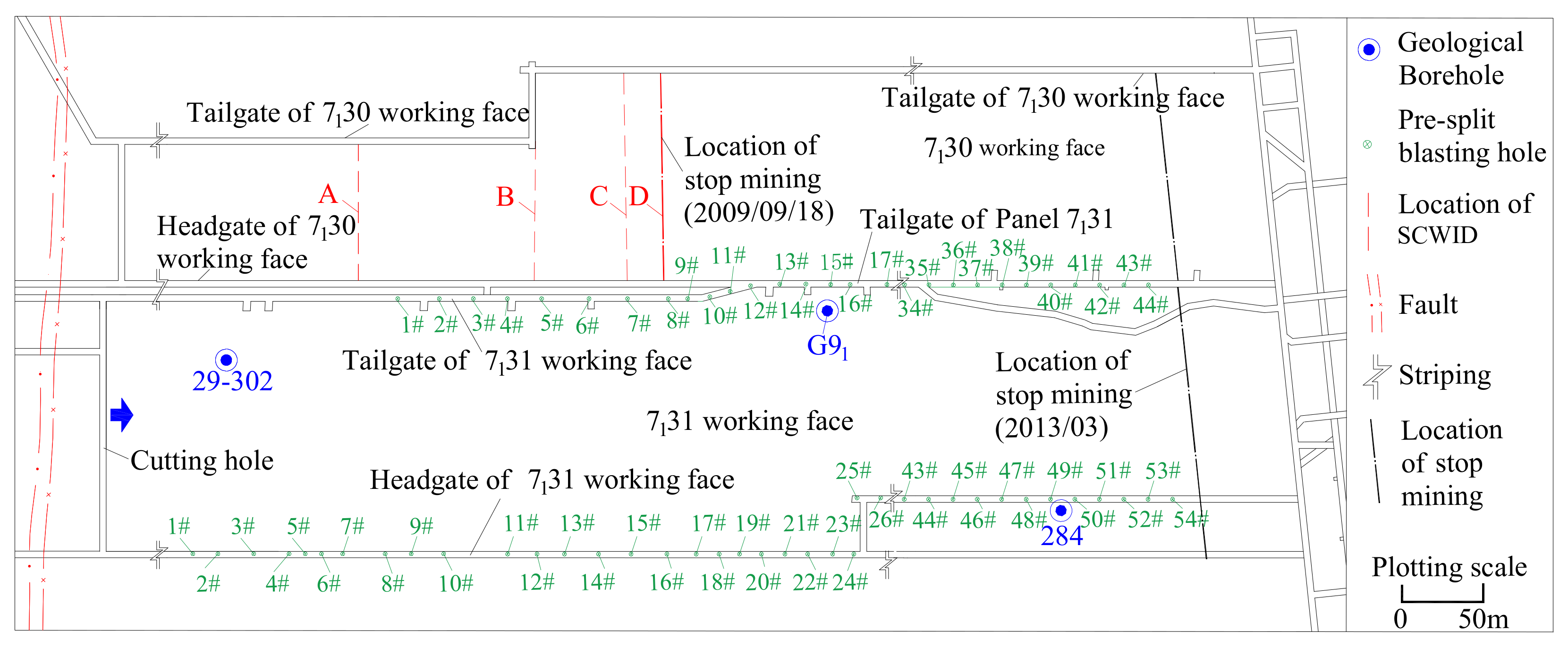
7131 working face is located in the third section of Qidong mine. The face width is 161 m and mining advance length is 1686.6 m. The average thickness of the coal seam is 3.5 m and the average dip angle of the coal seam is 13°. There are 91 two-prop shield hydraulic supports ZY10000/23.5/42, and rated working resistance is 10,000 kN. 7131 working face is adjacent to 7130 working face. Severe SCWID in the 7130 working face happened four times periodically during mining and finally they were compelled to stop production (see locations A,B,C,D in Figure 13). Therefore, it is important to predict whether the adjacent 7131 working face will appear the similar SCWID and, if at high risk, find ways to prevent possible disasters.
4.3.2. Prevention of SCWID in 7131 Working Face
Predicating Dangerous Area of SCWID
According to the prevention and control countermeasures of SCWID under the UCA, when the distance between the primary key stratum and the coal seam is less than 10 times the mining height, the overlying strata are easy to behave as a composite single key stratum structure, and the broken beam structure is easy to slide and lose stability after the breakage of the strata, causing the water inrush accident of the working face. Therefore, the target horizon of presplitting blasting is the primary key stratum within 10 times the coal seam height. It was found that within the 7–10 times mining height in overlying strata of 7131 working face, the thickness of the hard rock stratum is greater than 10 m, or even reaches 20 m. Therefore, targeted measures should be taken to avoid the disasters. The identification results are shown in Table 4.
As shown in Table 4, according to the judgment result of the key stratum, in the original rock strata, the layer of rock stratum with a thickness of 15.07 m, which is 0.47 m above the coal seam, is the primary key stratum, which plays a major controlling role in the movement of overlying rock strata. After its breakage, the overlying 12.31 m thick hard rock stratum is broken synchronously with it. At the same time, the thickness of the broken rock layer reaches the bottom of the thick loose layer with a thickness of 338.7 m. If the artificial presplitting blasting is carried out, the original 15.07 m thick hard key stratum close to the coal seam will be artificially weakened before the mining of the working face and become a damaged rock stratum, and the broken length will follow the distance length set by the artificial presplitting blasting, which will be less than the original broken length, and also less than the damaged length of the upper 12.31 m thick sandstone. After the roof presplitting blasting, the undamaged 12.31 m thick sandstone layer becomes the key layer which plays a major controlling role in the whole overlying strata movement. After blasting, the lower rock strata fully collapse, the length of the block is reduced, and the bulking coefficient is increased. When the upper key stratum is broken, the lower hanging space will be reduced, and the overall breakage of the key stratum will not occur again, thus avoiding the occurrence of water inrush accidents.
Artificial Pre-Split Blasting in 7131 Working Face
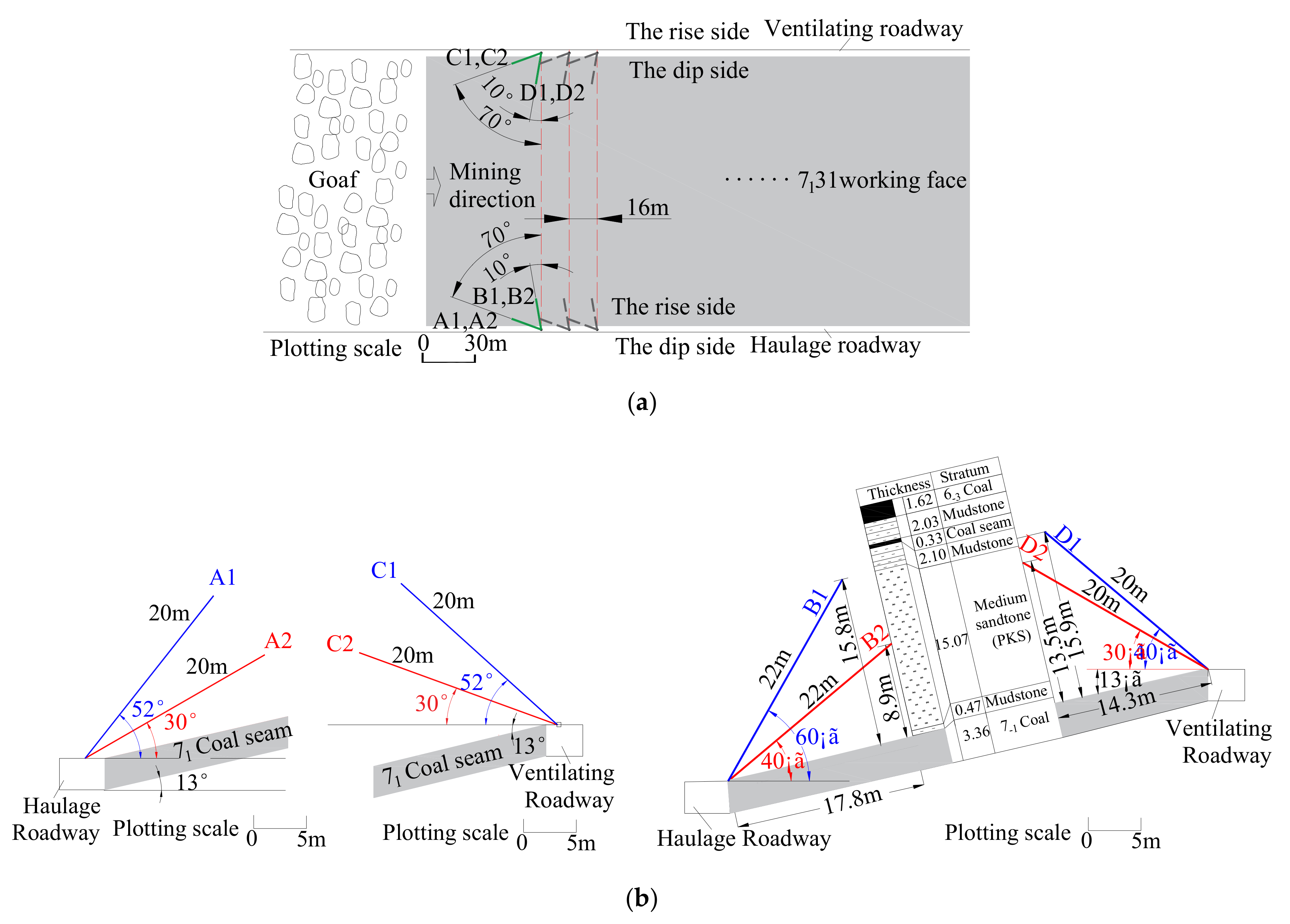
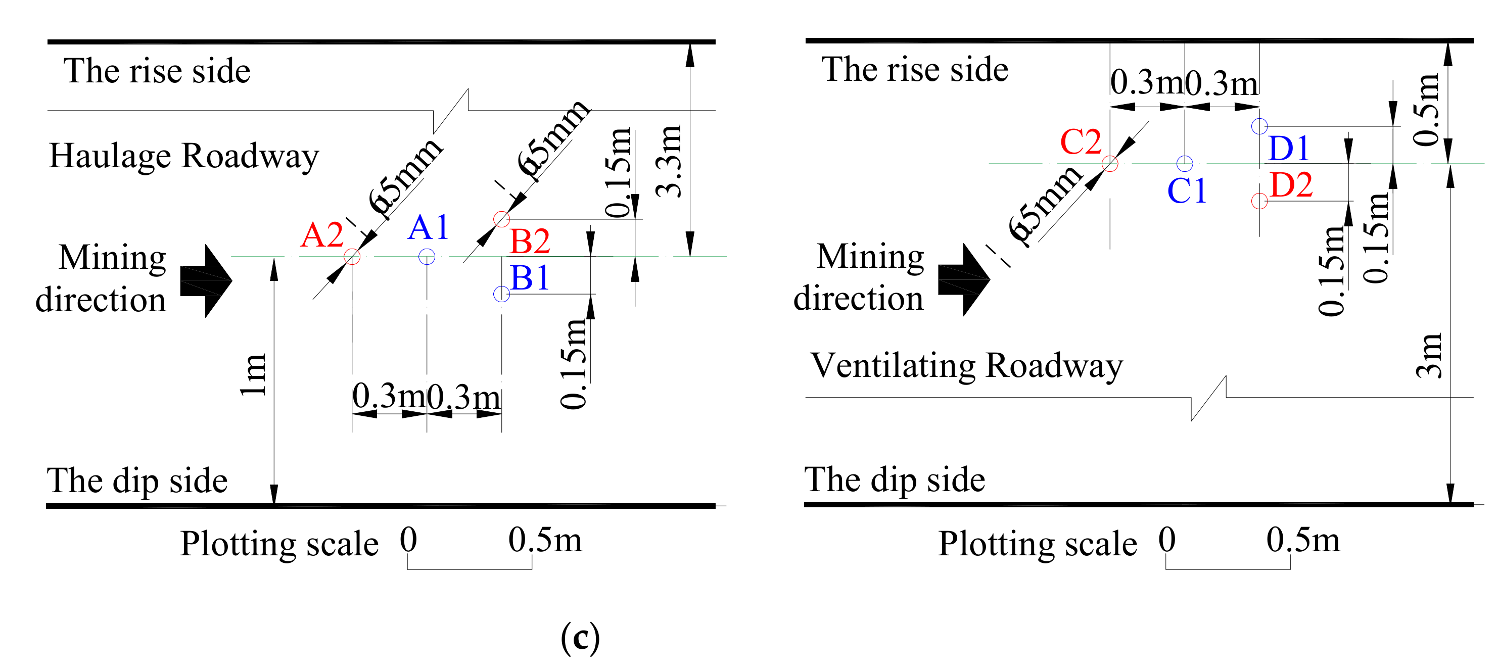
The artificial pre-split blasting method can be adopted to prevent the simultaneous breakage and large-scale overhang of the overlying strata. The pre-split blasting scheme has been designed based on the mechanism of the SCWID. In literature [30], the roof presplitting blasting in 7121 working face of Qidong coal mine was carried out, but due to the limited condition in the roadway, only one roadway was blasted. According to the conditions of 7131 working face, the previous technology is now improved and the roof blasting is carried out in both roadways of the working face to achieve a better result. Along the advancing direction, 65-mm-diameter drill holes were constructed from the roof of haulage and ventilating roadway to the goaf of working face at an interval of 16 m. Each group included four boreholes, as shown in Figure 14a, A1, A2, B1, B2 for the haulage roadway, and C1, C2, D1, D2 for the ventilating roadway. The boreholes with smaller inclined angle with the roadway strike direction were mainly used to cut off the rock strata, such as A1, A2, C1, and C2. A drill hole with a large inclined angle was mainly use for controlling that broken length of a rock stratum, such as B1, B2, D1, and D2. The angle between group A/C and the two vertical roadways was 70° and the angles between the two boreholes in the group and the horizontal plane were 30° and 52° respectively. The angle between group B/D and the two vertical roadways was 10°. The angle between group B and the horizontal plane was 40° or 60°, and that between group D and the horizontal plane was 30° or 40°. In each group of boreholes, the length of the boreholes was 20 m, the controlled vertical height was 15.9 m, and the depth of the boreholes was about 17.8 m in the vertical direction of the two roadways of the working face. The design scheme of roof pre-split blasting of 7131 working face is shown in Figure 14b. At each construction site, the hole is drilled from the top of the roadway to the direction of the goaf, and the locations of the holes are shown in Figure 14c.
Effect of Preventing Practice
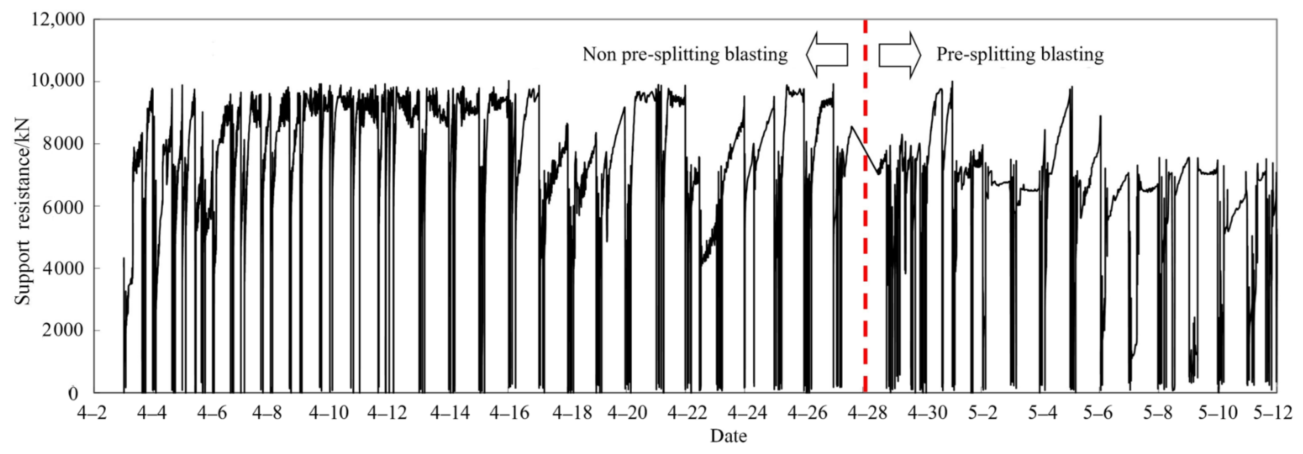
According to the previous analysis, 7131 working face had the risk of water inrush and support crushing. When the blasting was not carried out at the initial stage, the roof pressure was large and the distance of pressure behavior was long (Figure 15). After that, artificial pre-split blasting was implemented according to the mining conditions.
From the support resistance curve in Figure 15, it can be seen that when the working face is in the area of pre-split blasting, the support resistance is reduced. The roof weighting step and persistence length, the continue length of pressure reduced by 6.6 m, and the roof weighting step reduced by 6.7 m, indicating that the overall pressure strength decreases. Table 5 presents the pressure characteristics of the face before and after the presplit blasting. Practice has proven that artificial pre-split blasting can significantly reduce the roof pressure, change the fracture characteristics of the overlying strata and avoid the key strata breaking simultaneously.
Based on the mining conditions of 7131 working face in Qidong mine, the safe mining was achieved through the prediction of dangerous areas of SCWID and the implementation of roof pre-splitting blasting. No SCWID occurred in the operation of 7131 working face, and the safety production of 1.277 million tons’ coal was reached, which ensures the balance of exploitation, thereby creating remarkable economic benefits.
5. Conclusions
This paper has presented a study on the mechanism of the formation of the supports crushing and water inrush disasters (SCWIDs) when mining below the unconsolidated confined aquifer (UCA). The mechanism of overlying strata structural instability under the effect of load transfer through UCA has been revealed. Results show that, due to the mobility and real time replenishment characteristics of the UCA, the load of overburden soil layer is continuously acting on the underlying strata through the UCA, causing (1) the underlying strata breaking simultaneously and (2) the bond-beam structure sliding and instability occurring. Thus, the water flowing fractured zone is fully developed and connects the UCA, which is the fundamental reason of SCWID.
Based on the occurrence mechanism of SCWID, prediction methods of SCWID are formed. The discriminated method of the key stratum’s location and overburden structure of borehole columnar can be applied to determine the overall breakage-prone areas, namely the dangerous area of SCWID when mining under the UCA.
Based on the occurrence mechanism of SCWID, some prevention measures are proposed. First, dangerous areas should be predicted, so that the specific locations where actions need to be taken are selected. Then, artificial pre-split blasting technology can be used in the selected positions of key strata in the predicted dangerous areas. These precautionary measures have been applied successfully in the 7131 working face in Qidong coal mine. In-situ practice has shown that the SCWID did not happen in 7131 working face, thereby achieving the goal of safe mining under UCA.
Author Contributions
Conceptualization, X.W. and J.X.; formal analysis, W.Z.; writing—original draft preparation, X.W. and W.Z.; writing—review and editing, X.W. and J.X.; simulation experiment, X.W. and H.H.; resources and engineering experiment, X.F.; validation, X.W. and W.Z. All authors have read and agreed to the published version of the manuscript.
Funding
The Independent research project of State Key Laboratory of Coal Resources and Safe Mining, CUMT (SKLCRSM19X008), National Natural Science Foundation of China (52074265).
Institutional Review Board Statement
Not applicable.
Informed Consent Statement
Not applicable.
Data Availability Statement
The data presented in this study are available on request from the corresponding author.
Acknowledgments
We extended our sincere thanks to the related engineers in Qidong mine for their substantial support and help in field measurement, engineering detection. We also thank the staffs of State Key Laboratory of Coal Resources and Safe Mining for the simulation experiment. The authors also thanks Jingmin Xu, Southeast University for his great help in English translation.
Conflicts of Interest
The authors declare no conflict of interest.
References
- Zhang, J.C.; Shen, B.H. Coal mining under aquifers in China: A case study. Int. J. Rock Mech. Min. 2004, 41, 629–639. [Google Scholar] [CrossRef]
- State Bureau of Coal Industry. Regulations of Buildings, Water, Railway and Main Well Lane Leaving Coal Pillar and Press Coal Mining; China Coal Industry Publishing House: Beijing, China, 2017; pp. 73–78. (In Chinese) [Google Scholar]
- Tan, S.; Wu, J. Cause analysis of water bursting in 7114 mining face of 71 coal seam in Qidong colliery. Coal Min. Technol. 2006, 11, 64–67. (In Chinese) [Google Scholar]
- Chen, L.; Feng, X.; Xie, W.; Xu, D. Prediction of water-inrush risk areas in process of mining under the unconsolidated and confined aquifer: A case study from the Qidong coal mine in China. Environ. Earth Sci. 2016, 75, 706. [Google Scholar] [CrossRef]
- Wang, X. Study on occurrence condition and prevention of support crushing and water-inrush disaster during mining under unconsolidated confined aquifer. Ph.D. Dissertation, China University of Mining and Technology, Beijing, China, 2012. (In Chinese). [Google Scholar]
- Palchik, V. Formation of fractured zones in overburden due to longwall mining. Environ. Geol. 2003, 44, 28–38. [Google Scholar] [CrossRef]
- Palchik, V. Bulking factors and extents of caved zones in weathered overburden of shallow abandoned underground workings. Int. J. Mech. Min. Sci. 2015, 79, 227–240. [Google Scholar] [CrossRef]
- Qu, Q.; Xu, J.; Wu, R.; Qin, W.; Hu, G. Three-zone characterisation of coupled strata and gas behaviour in multi-seam mining. Int. J. Rock Mech. Min. Sci. 2015, 78, 91–98. [Google Scholar] [CrossRef]
- Rezaei, M.; Hossaini, M.F.; Majdi, A. A time-independent energy model to determine the height of destressed zone above the mined panel in longwall coal mining. Tunn. Undergr. Sp. Technol. 2015, 47, 81–92. [Google Scholar] [CrossRef]
- Mondal, D.; Roy, P.N.S.; Kumar, M. Monitoring the strata behavior in the destressed zone of a shallow indian longwall panel with hard sandstone cover using mine-microseismicity and borehole televiewer data. Eng. Geol. 2020, 271, 105593. [Google Scholar] [CrossRef]
- Karacan, C.O.; Ruiz, F.A.; Cote, M.; Phipps, S. Coal mine methane: A review of capture and utilization practices with benefits to mining safety and to greenhouse gas reduction. Int. J. Coal Geol. 2011, 86, 121–156. [Google Scholar] [CrossRef]
- Hill, J.G.; Price, D.R. The impact of deep mining on an overlying aquifer in western Pennsylvania. Groundw. Monit. Remediat. 1983, 3, 138–143. [Google Scholar] [CrossRef]
- Booth, C.J. Strata-movement concepts and the hydrogeological impact of underground coal mining. Groundwater 1986, 24, 507–515. [Google Scholar] [CrossRef]
- Kim, J.M.; Parizek, R.R.; Elsworth, D. Evaluation of fully-coupled strata deformation and groundwater flow in response to longwall mining. Int. J. Rock Mech. Min. 1997, 34, 1187–1199. [Google Scholar] [CrossRef]
- Islam, M.R.; Hayashi, D.; Kamruzzaman, A.B. Finite element modeling of stress distributions and problems for multi-slice longwall mining in Bangladesh, with special reference to the Barapukuria coal mine. Int. J. Coal Geol. 2009, 78, 91–109. [Google Scholar] [CrossRef]
- Yu, S.; Xu, J.; Zhu, W.; Wang, S.; Liu, W. Development of a combined mining technique to protect the underground workspace above confined aquifer from water inrush disaster. Bull. Eng. Geol. Environ. 2020, 79, 3649–3666. [Google Scholar] [CrossRef]
- Liu, T.Q. Theory and Techniques for Optimal Design of Outcrop Coal Pillar; China Coal Industry Publishing House: Beijing, China, 1998; pp. 42–48. (In Chinese) [Google Scholar]
- Kang, Y.; Zhao, K.; Liu, Z.; Tan, S.; Zhang, Y.; Yi, D.; Zhang, G.; Li, L. Devastating laws of overlying strata with fissure under high hydraulic pressure. J. Chin. Coal Soc. 2009, 34, 721–725. (In Chinese) [Google Scholar]
- Wang, X.; Xu, J.; Zhu, W.; Wang, H. Study on the influence of the characteristic of unconsolidated confined aquifer on its property of load transfer. J. Min. Saf. Eng. 2014, 31, 499–505. (In Chinese) [Google Scholar]
- Chen, L.; Feng, X.; Xu, D.; Zeng, W.; Zheng, Z. Prediction of water inrush areas under an unconsolidated, confined aquifer: The application of multi-information superposition based on GIS and AHP in the Qidong coal mine, China. Mine Water Environ. 2018, 37, 786–795. [Google Scholar] [CrossRef]
- Yang, B.; Wang, C.; Yan, C. Cause of water inrush in Qidong coal mine. Coal Geol. Exp. 2003, 31, 41–43. (In Chinese) [Google Scholar]
- Wang, X.; Xu, J.; Zhu, W.; Hao, X. Research on connected effect between water level variation of unconsolidated confined aquifer and roof weighting and its application. Chin. J. Rock Mech. Eng. 2011, 30, 1872–1881. (In Chinese) [Google Scholar]
- Xu, J.; Zhu, W.; Wang, X. Study on water-inrush mechanism and prevention during coal mining under unconsolidated confined aquifer. J. Min. Saf. Eng. 2011, 28, 333–339. (In Chinese) [Google Scholar]
- Xu, J.; Zhu, W.; Wang, X.; Yi, M. Classification of key strata structure of overlying strata in shallow coal seam. J. Chin. Coal Soc. 2009, 34, 865–870. (In Chinese) [Google Scholar]
- Ju, J.; Xu, J.; Zhu, W. Longwall chock sudden closure incident below coal pillar of adjacent upper mined coal seam under shallow cover in the shendong coalfield. Int. J. Rock Mech. Min. 2015, 77, 192–201. [Google Scholar] [CrossRef]
- Kuang, T.; Li, Z.; Zhu, W.; Xie, J.; Ju, J.; Liu, J.; Xu, J. The impact of key strata movement on ground pressure behaviour in the datong coalfield. Int. J. Rock Mech. Min. 2019, 119, 193–204. [Google Scholar] [CrossRef]
- Qian, M.; Miao, X.; Xu, J. Key Stratum Theory in Ground Control; China University of Mining and Technology Press: Xuzhou, China, 2003; p. 120. (In Chinese) [Google Scholar]
- Wang, X.; Xu, J.; Zhu, W.; Hao, H. Overburden structure influence to support crushing and water inrush during mining under unconsolidated confined aquifer. J. Min. Saf. Eng. 2014, 31, 838–844. (In Chinese) [Google Scholar]
- Wang, X.; Xu, J.; Wu, Y.; Wang, H.; Han, H.; Ji, Y. The influence of repeated mining on failure characteristic of overburden strata under unconsolidated confined aquifer. J. Min. Saf. Eng. 2017, 34, 437–443. (In Chinese) [Google Scholar]
- Wang, X.; Xu, J.; Zhu, W.; Li, Y. Roof pre-blasting to prevent support crushing and water-inrush accidents. Int. J. Min. Sci. Technol. 2012, 22, 379–384. [Google Scholar] [CrossRef]
Figure 1.
Schematic diagram of waterproof coal/rock pillar/layer for mining under unconsolidated confined aquifer (UCA).
Figure 1.
Schematic diagram of waterproof coal/rock pillar/layer for mining under unconsolidated confined aquifer (UCA).

Figure 2.
Actual water inrush and support crushing situation in the working face: (a) the central support crushed; (b) motor crushed at coal face end.
Figure 2.
Actual water inrush and support crushing situation in the working face: (a) the central support crushed; (b) motor crushed at coal face end.

Figure 3.
Schematic diagram of influence on different key stratum (KS) breakage on water flowing fracture: (a) KS1 breaks without UCA; (b) KS2 breaks without UCA; (c) two KSs break entirely with UCA.
Figure 3.
Schematic diagram of influence on different key stratum (KS) breakage on water flowing fracture: (a) KS1 breaks without UCA; (b) KS2 breaks without UCA; (c) two KSs break entirely with UCA.

Figure 4.
Simulation experiment system: (a) simulation experiment system; (b) loading equipment; (c) pressure sensor and rubber bag with water; (d) water supply.
Figure 4.
Simulation experiment system: (a) simulation experiment system; (b) loading equipment; (c) pressure sensor and rubber bag with water; (d) water supply.

Figure 5.
Strata breakage and movement between the scenarios without UCA: (a) advance 60 cm; (b) KS1 broken; (c) KS2 broken.
Figure 5.
Strata breakage and movement between the scenarios without UCA: (a) advance 60 cm; (b) KS1 broken; (c) KS2 broken.

Figure 6.
Strata breakage and movement between the scenarios with UCA: (a) advance 53 cm; (b) advance 67 cm; (c) KS broken.
Figure 6.
Strata breakage and movement between the scenarios with UCA: (a) advance 53 cm; (b) advance 67 cm; (c) KS broken.

Figure 7.
Press curve of observation with the mining distance.

Figure 8.
Location of detecting borehole in 7114 working face.

Figure 9.
Relationship between water inflow and water-level variation in 7114 working face.

Figure 10.
Drilling results of water flowing fracture height in 7114 working face.

Figure 11.
Prediction of dangerous area of SCWID at No.71 coal seam in Qidong coal mine

Figure 12.
Sketch about mechanism of roof pre-split blasting measure to SCWID: (a) first weighting without blasting; (b) periodic weighting without blasting; (c) first weighting using blasting; (d) periodic weighting using blasting.
Figure 12.
Sketch about mechanism of roof pre-split blasting measure to SCWID: (a) first weighting without blasting; (b) periodic weighting without blasting; (c) first weighting using blasting; (d) periodic weighting using blasting.


Figure 13.
Location of pre-split blasting holes in 7131 working face.

Figure 14.
Design scheme of roof pre-split blasting: (a) plan position of pre-split blasting; (b) scheme of borehole; (c) hole location of pre-split blasting.
Figure 14.
Design scheme of roof pre-split blasting: (a) plan position of pre-split blasting; (b) scheme of borehole; (c) hole location of pre-split blasting.


Figure 15.
Pressure curve before and after pre-split blasting.


Table 1.
Statistics of supports crushing and water inrush disasters (SCWIDs) in Qidong coal mines when mining under the UCA.
Table 1.
Statistics of supports crushing and water inrush disasters (SCWIDs) in Qidong coal mines when mining under the UCA.
| Working Face | Width and Mining Height of Working Face (m) | Supports Model | Serial No. and Time of SCWID | Bedrock Thickness (m) | Water Pressure (MPa) | Disaster Position | Situation |
|---|---|---|---|---|---|---|---|
| 3222 | 150/2.5 | ZZ4400-17/35 | 1/2001.11.25 | 66 | 3.7 | Dip advance 43 m | All supports crushed, 1520 m3/h |
| 3221 | 150/2.5 | Single Hydraulic Prop | 2/2002.09.16 | 99 | 3.9 | Dip advance 71 m | 100 props crushed, 239 m3/h |
| 3/2002.12.15 | 130 | 3.9 | Dip advance 100 m | 100 props crushed. 178 m3/h | |||
| 7114 | 174/2.6 | ZZ4400-17/35 | 4/2004.07.29 | 72 | 3.7 | Dip advance 44 m | 116 supports crushed, 71 m3/h |
| 5/2005.01.16 | 80 | 3.7 | Dip advance 184 m | 22 supports crushed, 169 m3/h | |||
| 7112 | 85/2.6 | ZZ4400-17/35 | 6/2006.10.01 | 128 | 3.9 | Dip advance 244.5 m | 35 supports crushed, 85 m3/h |
| 7130 | 88-134/3.7 | ZY6000/18.5/38 | 7/2009.05.03 | 48 | 3.2 | Strike advance 150 m | 23 props shrunk, 91 m3/h |
| 8/2009.06.07 | 43 | 3.2 | Strike advance 343 m | 30 props shrunk, 260 m3/h | |||
| 9/2009.06.29 | 47 | 3.2 | Strike advance 450 m | 6 props shrunk, 850 m3/h | |||
| 10/2009.08.29 | 44 | 3.2 | Strike advance 56 m | 8 props shrunk, 92 m3/h | |||
| 6130 | 126/1.67 | ZY4000-09/21 | 11/2009.09.13 | 45 | 3.2 | Strike advance 343 m | 16 supports crushed, 60 m3/h |
| 12/2009.10.24 | 42.5 | 3.2 | Strike advance 397 m | 2 supports crushed, 24 m3/h | |||
| 13/2009.11.14 | 43 | 3.2 | Strike advance 469 m | 47 supports crushed, 53 m3/h | |||
| 14/2010.01.24 | 68.1 | 3.2 | Strike advance 571 m | 6 supports crushed, 70 m3/h | |||
| 7121 | 129/1.96 | ZY5000-13/28 | 15/2009.11.24 | 72 | 3.7 | Strike advance 358 m | 40 supports crushed, 50 m3/h |
| 16/2010.07.24 | 113 | 3.7 | Strike advance 675 m | 8 supports crushed, 30 m3/h |
Table 2.
Mechanics parameters of the overlying strata.
| No | Stratum | Thickness (cm) | Unit Weight (kN·m−3) | Elastic Modulus (GPa) | Cohesion (MPa) | Internal Friction Angle (°) | Poisson’s Ratio |
|---|---|---|---|---|---|---|---|
| 1 | Unconsolidated formation | 50 | 16.0 | 0.064 | 0.016 | 25 | 0.4 |
| 2 | UCA | 20 | - | - | - | - | - |
| 3 | Zone of weathering | 3 | 16.0 | 0.064 | 0.032 | 25 | 0.35 |
| 4 | Soft strata | 16 | 17.6 | 0.120 | 0.032 | 33 | 0.33 |
| 5 | KS2 | 6 | 18.5 | 0.240 | 0.064 | 40 | 0.25 |
| 6 | Soft strata | 12 | 17.6 | 0.120 | 0.032 | 33 | 0.33 |
| 7 | KS1 | 5 | 18.5 | 0.240 | 0.064 | 40 | 0.25 |
| 8 | Roof | 12 | 16.0 | 0.080 | 0.032 | 28 | 0.33 |
| 9 | Coal seam | 4 | 12.0 | 0.032 | 0.012 | 23 | 0.33 |
| 10 | Floor | 5 | 18.5 | 0.240 | 0.064 | 40 | 0.27 |
Table 3.
Discrimination results of key strata location at different geological borehole.
| A: Borehole No.24-257 (Dangerous) | B: Borehole No.Caiqian3 (Safe) | C: Borehole No.296 (Dangerous) | |||||||||
|---|---|---|---|---|---|---|---|---|---|---|---|
| Thickness /m | Depth /m | Lithology | Position | Thickness /m | Depth /m | Lithology | Position | Thickness /m | Depth /m | Lithology | Position |
| 375.80 | 0.00 | Unconsolidated formation | - | 375.65 | 0.00 | Unconsolidated formation | - | 375.60 | 0.00 | Unconsolidated formation | - |
| 2.80 | 375.80 | Mudstone | - | 9.88 | 375.65 | Mudstone | - | 5.61 | 375.60 | Mudstone | - |
| 6.18 | 378.60 | Siltstone | - | 2.49 | 385.53 | Siltstone | - | 3.64 | 381.21 | Siltstone | - |
| 8.98 | 384.78 | Mudstone | - | 5.04 | 388.02 | Mudstone | - | 5.81 | 384.85 | Sandy mudstone | - |
| 1.83 | 393.76 | Oolitic mudstone | - | 0.93 | 393.06 | Siltstone | - | 11.35 | 390.66 | Mudstone | - |
| 1.20 | 395.59 | Mudstone | - | 0.68 | 393.99 | Fine sandstone | - | 4.73 | 402.01 | Medium sandstone | - |
| 0.70 | 396.79 | Coal seam | - | 1.91 | 394.67 | Mudstone | - | 9.16 | 406.74 | Mudstone | - |
| 2.22 | 397.49 | Mudstone | - | 8.36 | 396.58 | Fine sandstone | PKS | 0.98 | 415.90 | Siltstone | - |
| 3.29 | 399.71 | Oolitic mudstone | - | 5.23 | 404.94 | Mudstone | - | 20.29 | 416.88 | Mudstone | - |
| 1.45 | 403.00 | Siltstone | - | 2.21 | 410.17 | Silty mudstone | - | 8.96 | 437.17 | Fine sandstone | - |
| 3.04 | 404.45 | Mudstone | - | 2.29 | 412.38 | Mudstone | - | 6.11 | 446.13 | Siltstone | - |
| 1.34 | 407.49 | Oolitic mudstone | - | 0.44 | 414.67 | 61 Coal seam | - | 4.70 | 452.24 | Fine sandstone | - |
| 0.39 | 408.83 | Coal seam | - | 1.52 | 415.11 | Mudstone | - | 0.25 | 456.94 | Coal seam | - |
| 2.41 | 409.22 | Siltstone | - | 0.64 | 416.63 | 62 Coal seam | - | 1.17 | 457.19 | Mudstone | - |
| 7.11 | 411.63 | Mudstone | - | 1.17 | 417.27 | Mudstone | - | 0.54 | 458.36 | 61 Coal seam | - |
| 2.96 | 418.74 | Oolitic mudstone | - | 3.62 | 418.44 | Siltstone | - | 1.42 | 458.90 | Mudstone | - |
| 7.61 | 421.70 | Siltstone | - | 7.78 | 422.06 | Mudstone | - | 3.84 | 460.32 | Siltstone | - |
| 1.30 | 429.31 | Medium sandstone | - | 0.88 | 429.84 | Fine sandstone | - | 4.92 | 464.16 | Mudstone | - |
| 1.39 | 430.61 | Mudstone | - | 3.80 | 430.72 | Siltstone | - | 1.00 | 469.08 | Siltstone | - |
| 0.24 | 432.00 | 60 Coal seam | - | 2.19 | 434.52 | Medium sandstone | KS2 | 10.73 | 470.08 | Medium sandstone | PKS |
| 0.10 | 432.24 | Mudstone | - | 3.80 | 436.71 | Silty mudstone | - | 4.14 | 480.81 | Mudstone | - |
| 0.22 | 432.34 | 60 Coal seam | - | 0.88 | 440.51 | Fine sandstone | - | 1.48 | 484.95 | Fine sandstone | KS1 |
| 4.21 | 432.56 | Mudstone | - | 2.35 | 441.39 | Mudstone | - | 0.59 | 486.43 | Carbon mudstone | - |
| 1.50 | 436.77 | Medium sandstone | - | 2.74 | 443.74 | Fine sandstone | KS1 | 0.61 | 487.02 | Mudstone | - |
| 4.04 | 438.27 | Mudstone | - | 3.64 | 446.48 | Mudstone | - | 2.63 | 487.63 | 71 Coal seam | - |
| 1.71 | 442.31 | 61 Coal seam | - | 3.01 | 450.12 | 71 Coal seam | - | / | / | / | / |
| 4.76 | 444.02 | Mudstone | - | / | / | / | / | / | / | / | / |
| 2.82 | 448.78 | Siltstone | - | / | / | / | / | / | / | / | / |
| 2.19 | 451.60 | Mudstone | - | / | / | / | / | / | / | / | / |
| 0.45 | 453.79 | 62 Coal seam | - | / | / | / | / | / | / | / | / |
| 0.47 | 454.24 | Mudstone | - | / | / | / | / | / | / | / | / |
| 0.70 | 454.71 | 62 Coal seam | - | / | / | / | / | / | / | / | / |
| 2.76 | 455.41 | Mudstone | - | / | / | / | / | / | / | / | / |
| 14.17 | 458.17 | Siltstone | PKS | / | / | / | / | / | / | / | / |
| 3.42 | 472.34 | Mudstone | - | / | / | / | / | / | / | / | / |
| 2.76 | 475.76 | 71 Coal seam | - | / | / | / | / | / | / | / | / |
Table 4.
Results of the key stratum location of borehole No.29-302 near 7131 working face.
| Thickness/m | Depth/m | Lithology | Before Blasting | After Blasting |
|---|---|---|---|---|
| 338.70 | 0.00 | Unconsolidated formation | - | - |
| 4.40 | 338.70 | Claystone | - | - |
| 18.42 | 343.10 | Mudstone | - | - |
| 0.30 | 361.52 | Coal seam | - | - |
| 4.12 | 361.82 | Mudstone | - | - |
| 0.19 | 365.94 | Coal seam | - | - |
| 2.79 | 366.13 | Mudstone | - | - |
| 0.80 | 368.92 | 60 Coal seam | - | - |
| 6.84 | 369.72 | Mudstone | - | - |
| 1.79 | 376.56 | 61 Coal seam | - | - |
| 5.14 | 378.35 | Mudstone | - | - |
| 12.31 | 383.49 | Madium sandstone | Hard rock-KS2 | Hard rock-KS |
| 0.70 | 395.80 | Mudstone | - | - |
| 0.41 | 396.50 | Carbon Mudstone | - | - |
| 1.62 | 396.91 | 62 Coal seam | - | - |
| 2.03 | 398.53 | Mudstone | - | - |
| 0.33 | 400.56 | Coal seam | - | - |
| 2.10 | 400.89 | Mudstone | - | - |
| 15.07 | 402.99 | Madium sandstone | Hard rock-KS1(Pre-split blasting) | Broken rock |
| 0.47 | 418.06 | Mudstone | - | - |
| 3.36 | 418.53 | 71 Coal seam | - | - |
Table 5.
Comparison of pressure characteristics before and after pre-split blasting.
| Stage | Average Support Resistance (kN) | Continue Length of Pressure (m) | Roof Weighting Step (m) |
|---|---|---|---|
| Before (A) | 10,241 | 14.8 | 28.4 |
| After (B) | 9944 | 8.2 | 21.7 |
| Difference (A-B) | 297 | 6.6 | 6.7 |
Publisher’s Note: MDPI stays neutral with regard to jurisdictional claims in published maps and institutional affiliations. |
© 2021 by the authors. Licensee MDPI, Basel, Switzerland. This article is an open access article distributed under the terms and conditions of the Creative Commons Attribution (CC BY) license (http://creativecommons.org/licenses/by/4.0/).
Share and Cite
MDPI and ACS Style
Wang, X.; Zhu, W.; Xu, J.; Han, H.; Fu, X. Mechanism of Overlying Strata Structure Instability during Mining below Unconsolidated Confined Aquifer and Disaster Prevention. Appl. Sci. 2021, 11, 1778. https://doi.org/10.3390/app11041778
AMA Style
Wang X, Zhu W, Xu J, Han H, Fu X. Mechanism of Overlying Strata Structure Instability during Mining below Unconsolidated Confined Aquifer and Disaster Prevention. Applied Sciences. 2021; 11(4):1778. https://doi.org/10.3390/app11041778
Chicago/Turabian StyleWang, Xiaozhen, Weibing Zhu, Jialin Xu, Hongkai Han, and Xiang Fu. 2021. "Mechanism of Overlying Strata Structure Instability during Mining below Unconsolidated Confined Aquifer and Disaster Prevention" Applied Sciences 11, no. 4: 1778. https://doi.org/10.3390/app11041778
Note that from the first issue of 2016, this journal uses article numbers instead of page numbers. See further details here.