


Effect of Interstage Pipeline on the Performance of Two-Stage Centrifugal Compressors for Automotive Hydrogen Fuel Cells
1
School of Control Engineering, Northeastern University at Qinhuangdao, Qinhuangdao 066004, China
2
School of Electrical Engineering, Southeast University, Nanjing 210018, China
3
School of Vehicle and Mobility, Tsinghua University, Beijing 100084, China
*
Author to whom correspondence should be addressed.
Appl. Sci. 2023, 13(1), 503; https://doi.org/10.3390/app13010503
Submission received: 5 December 2022
/
Revised: 21 December 2022
/
Accepted: 28 December 2022
/
Published: 30 December 2022
(This article belongs to the Special Issue Hybrid, Hydrogen, and Electric Vehicles: Energy Management, Optimizations Techniques, and Control Systems)
Abstract
:At present, two-stage centrifugal compressors based on air bearing and high-speed motor technology are widely used in automotive hydrogen fuel cells. The low-pressure stage and high-pressure stage of the compressor are directly connected through an interstage pipeline, thus the structure of the interstage pipeline has an important influence on the aerodynamic performance of the compressor. In this work, a two-stage compressor with three different interstage pipelines were investigated experimentally and numerically. Results show that affected by the interstage pipeline bend section, the flow distortion will be induced at the impeller inlet of the high-pressure stage, and the distortion intensity changes with the pipeline structure. Among the three models, the EPC (elbow pipe change) model induces the most intense total pressure distortion at the condition of 80 kr/min and 130% mass flow rate, resulting in an efficiency reduction of 2 and 1.5 percentage points compared with the SPC (straight pipe change) and the TPC (total pipe change) model, respectively. Further research indicates that the upstream distortion has obvious influence on the downstream rotor blades. As the blade height decreases, the load becomes more uniform on the main blades, while the load extremum migrates to the trailing edge on the splitter blades. Finally, three models are tested, and their performance is compared at three typical rotational speeds., It is recommended that interstage pipelines similar to SPC models should be chosen to improve the two-stage compressor efficiency in the design.
1. Introduction
Hydrogen fuel cell (HFC) is a device that converts chemical energy from hydrogen and oxygen into electricity with water as its byproduct. It is of great significance for solving the global energy shortage and environmental pollution. Compared with traditional heat engines, HFCs are not limited by the Carnot cycle, having high power density and greater efficiency as high as 60% in electrical energy conversion and overall 90% when the stack exhaust can be recovered effectively. Therefore, HFCs are a great energy source and could be widely used in vehicles and fixed power generation devices [1,2,3,4]. HFC systems are mainly composed of fuel cell stacks, a hydrogen supply system, cathode gas supply (oxygen) system, hydrothermal management system and control system. As the main component of cathode gas supply system, the centrifugal compressor is related to the performance of the whole fuel cell system since the intake pressure of the stack has a direct impact on the power density of the HFC [5,6].
Compressors used for HFC systems are significantly different from those for internal combustion engines in terms of operation mode and structure [7,8,9,10], in which the high- speed motor is coaxial connected with the impeller as the power source, while the compressor used in the internal combustion engines is driven by the exhaust gas turbine through recycling the engine exhaust energy [11,12,13,14]. The main reason for the difference between the two driving modes is that the stack exhaust energy is not enough to drive the compressor, so the compressor must consume the electric energy generated by the stack, and with the increase of the mass flow rate (MFR) and pressure ratio, the energy consumed by the compressor also increases. Studies have shown that in HFC systems, compressor power consumption is close to 20% of the system power [15].
In the case of a 120 kW HFC system, the maximum compressor speed is 100 kr/min due to the influence of rotor weight and shafting stability, and the required MFR and pressure ratio of the stack are generally 0.15 kg/s and 2.8, respectively. If the compressor uses a single-stage compression form, this allows the impeller to have a lower specific speed and isentropic efficiency [16,17,18,19]; while the compressor with two-stage compression technology can effectively solve the problem caused by the specific speed, it is therefore widely used in HFC systems at present. However, the layout of the two-stage centrifugal compressor needs to meet the requirement of compact overall structure, which forces the interstage pipeline connecting the low-pressure stage (LPS) and the high-pressure stage (HPS) to be bent and twisted, leading to the pressure distortion and efficiency penalty of the HPS. Therefore, it has important engineering application value to study the influence of interstage pipeline on the performance and internal flow of two-stage compressors used in HFCs. However, to date, no related research literature has been reported, since most is still focused on the single-stage centrifugal compressors [20,21,22,23,24]. The experimental study performed by Ariga [25] in a single-stage centrifugal compressor revealed that by changing the installation form of honeycomb mesh angles, radial and circumferential pressure distortion were generated at the impeller inlet. The intake distortion changes the inlet attack angle of the impeller, which significantly reduces the impeller efficiency, and the surge line of the compressor deviates to the direction of low flow. The research of Zemp [26] and Brune [27] showed that when the inlet pressure distortion is generated, the blade load fluctuation amplitude was the largest at the blade leading edge, while with the MFR decreases, the amplitude of the load fluctuation also decreases. Kim [28] studied the effects of straight and bend pipes on compressor performance through experiments and numerical methods, showing that when the 90°-bend pipe is connected to the inlet of the compressor, the flow distortion will occur and significantly reduce the compressor performance; when the internal structure of the bend pipe is changed and the guide plate is added at the appropriate position, the influence of the secondary flow brought by the bend can be reduced. Without the guide plate, the performance of the compressor and diffuser can be improved. In view of the form of bend inlet diversion in literature [28], the research of Engeda [29] showed that the inlet bend with guide vane could increase the compressor stage efficiency by 3%, and the uneven flow at the compressor inlet inevitably causes the distortion of the flow inside the compressor, leading to the forced response of the blades. Kammerer [30] experimentally studied the unsteady pressure fluctuation of compressor blades under forced response when the inlet flow is distorted and measured the resonance and non-resonance conditions by installing pressure sensors on the blade surface. Dickmann [31,32] investigated the compressor blade excitation under the condition of inlet distortion caused by bend pipes and showed that the blade amplitude varied with the MFR. Furthermore, the circumferential asymmetrical static pressure distribution is used to simulate the volute at the diffuser outlet. It is proved that the non-axis symmetrical property of the volute and the inlet pipe have great influence on the vibration of the blade. Wang [33] and Li [34] experimentally studied the influence of radial distortion of inlet total pressure on the performance of a centrifugal compressor. By installing a radial distortion net in front of the inlet guide vane, a ring radial combined total pressure distortion is created at both tip and root of the blades, and its comprehensive effect is beneficial to the operation of the centrifugal compressor, and the measured pressure ratio and efficiency are higher than those without distortion, besides, its surge margin is also widened.
The above literature systematically studies the influence of compressor inlet distortion on its performance and internal flow. For the two-stage centrifugal compressors used in HFCs, there must be a distortion at the impeller inlet for HPS due to the existence of the interstage pipelines. Since, there is limited relevant research on the bend intake of two-stage centrifugal compressors, it is of great significance to study the effects of interstage pipelines on the performance and internal flow of two-stage centrifugal compressors for HFCs. In this work, a two-stage centrifugal compressors applicated in a 120 kW HFC system with different interstage pipelines were studied numerically and experimentally; the influence of the interstage pipelines structure on their internal flow and loss patterns were analyzed. The inlet distortion of downstream HPS compressors is compared in three models, and the performance and flow loss characteristics of the HPS compressor is emphasized. Finally, three kinds of interstage pipes are manufactured, and their performance is tested and compared.
2. Research Model and Numerical Methods
2.1. Geometry and Main Parameters of the Study Model
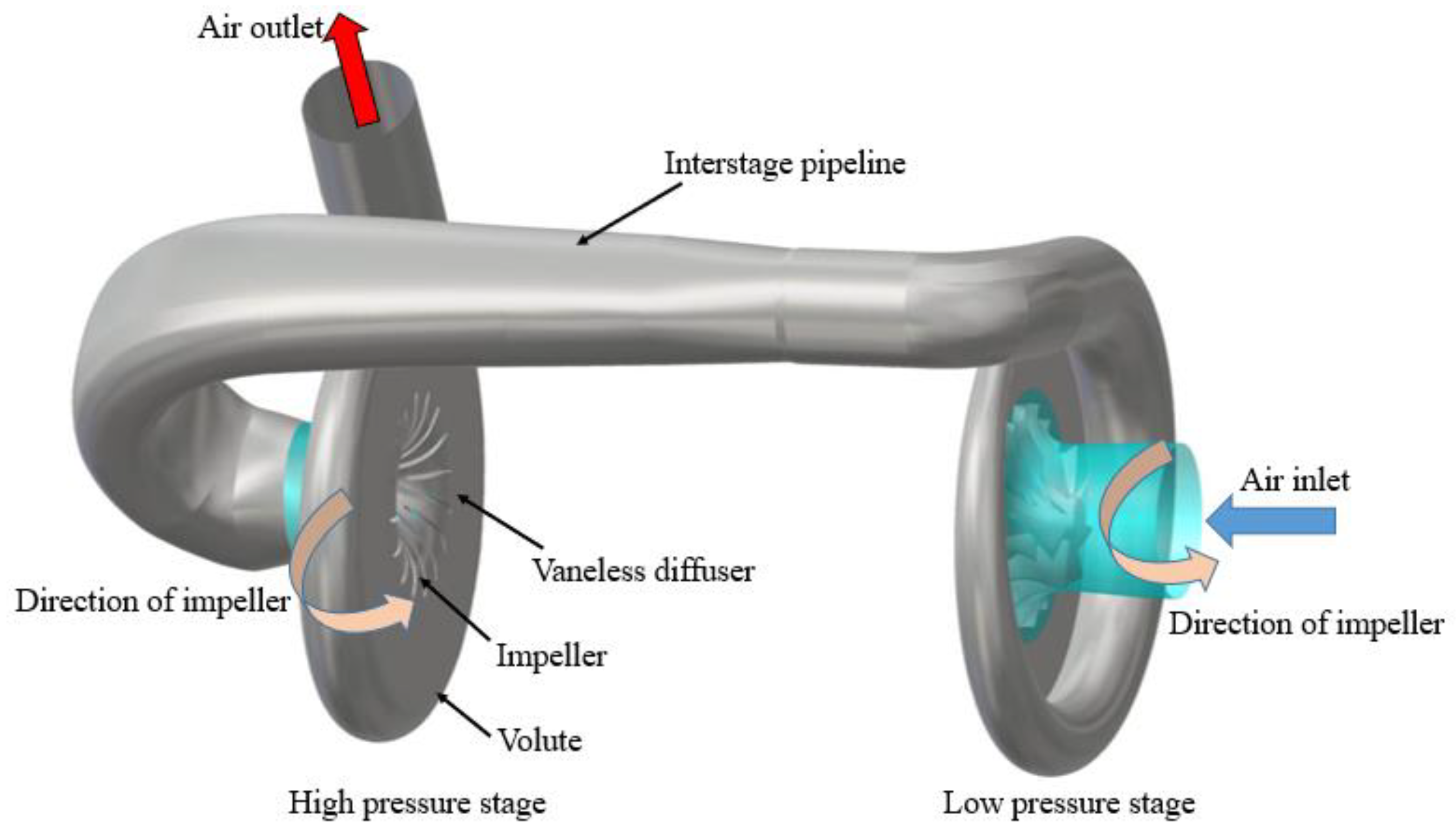
The research model is a two-stage centrifugal compressor applied to a 120 kW HFC system. It has a rated speed of 80 kr/min, a rated flow rate of 0.15 kg/s and a designed pressure ratio of 2.9. The compressor has an inlet duct, a LPS, a HPS and an interstage pipeline with EPC type. The geometry of the research model is shown in Figure 1, and the main geometric parameters of it is listed in Table 1.
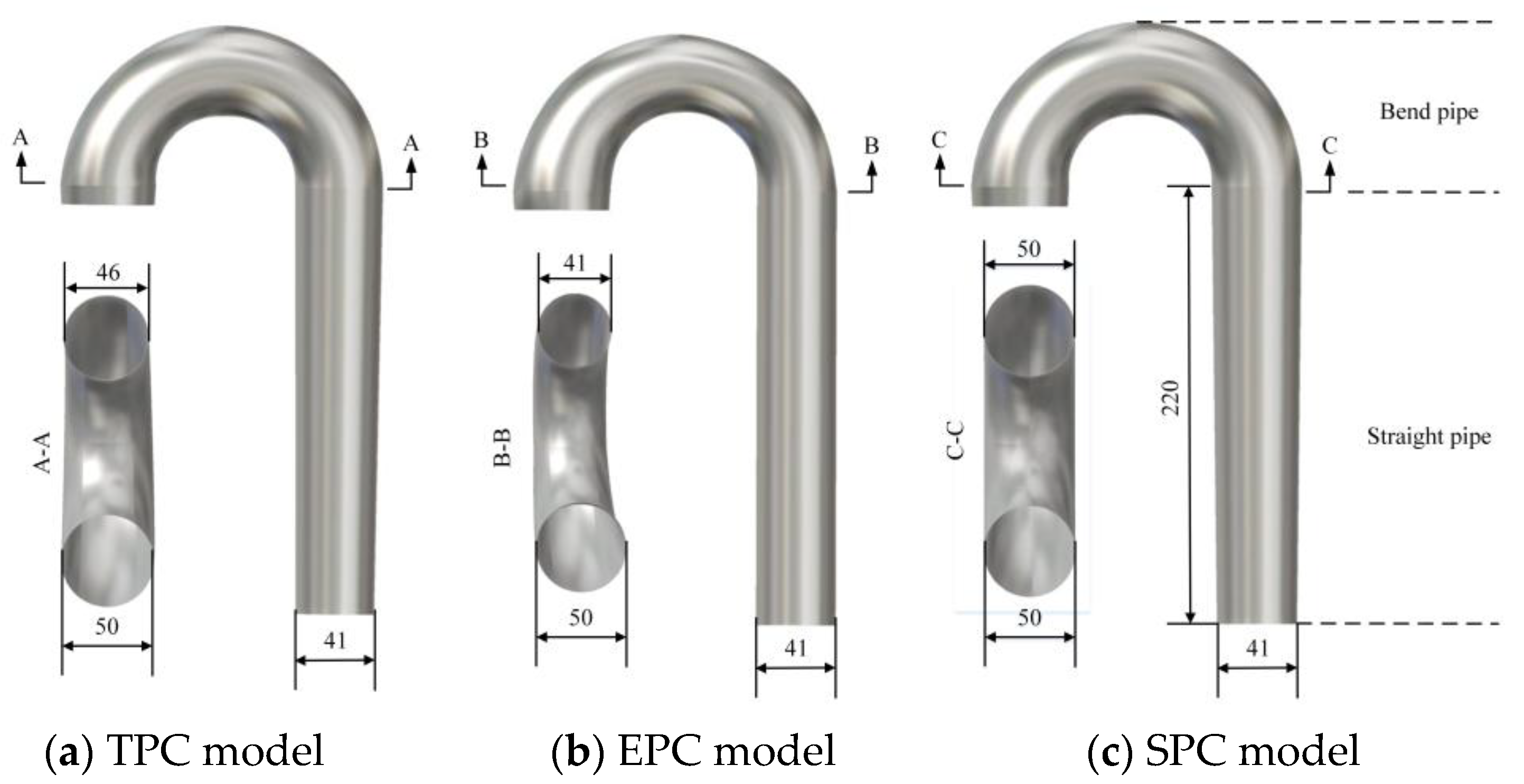
Since the outlet diameter of the LPS is smaller than the inlet diameter of the HPS, the shape of the pipeline between the two stages is gradually changed along the radial direction, which will directly affect the flow field of the HPS impeller inlet thus reducing the compressor efficiency. In this work, three kinds of interstage pipelines with different gradient rules of cross-sectional area are designed. The shape of the three models with the relevant dimensions are shown in Figure 2. Among them, the TPC model has an overall uniform increase in internal diameter in both bend and straight sections, as shown in Figure 2a; the EPC model with the inner diameter of bend section uniformly changing and the inner diameter of straight section constant, as shown in Figure 2b; the model of SPC has a uniform increase in the internal diameter of the straight section and a constant internal diameter of the bend section, as shown in Figure 2c.
2.2. Numerical Method and Mesh
The Navier-Stokes equation is solved by the FINE/Turbo in NUMECA software, and the Spalart-Allmaras (S-A) equation was selected as the turbulence model; the difference scheme used in the study is a second order central difference scheme, and the fourth order Runge-kutta is used for iterative calculation. In order to improve the computational efficiency, multiple meshing, local time step and implicit residual smoothing were adopted to accelerate the convergence. For the transfer of the physical quantities, the “rotor freezing method” was applied to the interface between the rotor and the stator. The compressor inlet condition is set as constant and uniform axial air intake, and the whole solid wall of the compressor is chosen as adiabatic without slip. For the outlet condition, the given MFR is adopted, and then other physical quantities such as pressure ratio and efficiency are derived by the calculations. The governing equations can be expressed as:
where and are the inviscid and viscous flux vectors, respectively. Q is the source term. and can be further decomposed into Cartesian components as follows:
The Spalart-Allmaras turbulence model and the perfect gas equation were applied to enclose the above equations. The perfect gas equation can be written as follow:
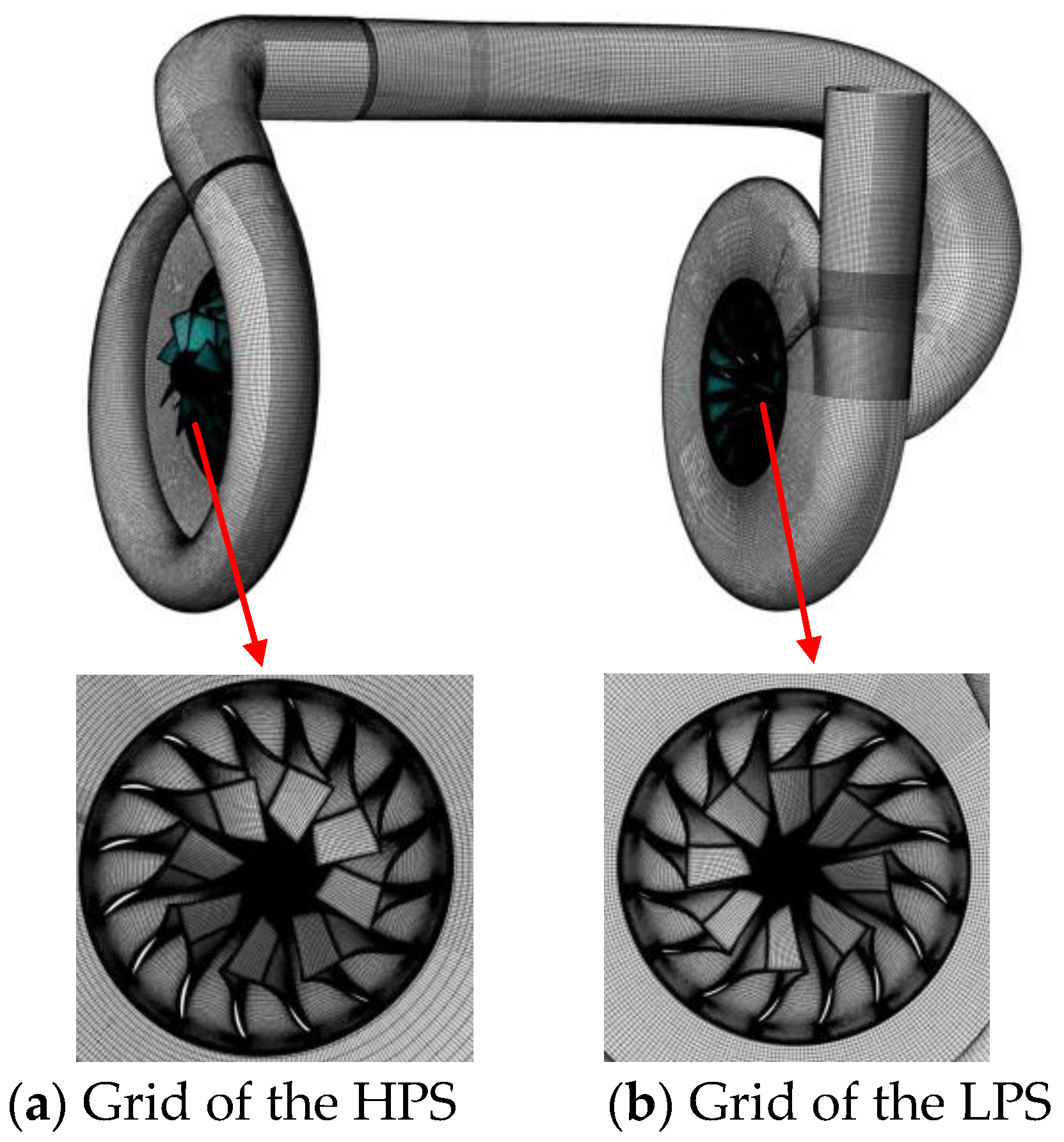
Figure 3 shows the grid of the study model, in which the impeller and diffuser grid is automatically generated, having the O4H topology pattern. A H-type topology surrounded by an O-type topology was applied in the rotor blade tip clearance, with 17 layers in the spanning direction. The boundary between diffuser and volute is generated by perfect matching connection, and the two are integrated into a computing domain. Since the volute as well as the interstage pipe are asymmetric geometry, the butterfly topology pattern is adopted to improve the grid accuracy.
A grid independence study was performed by steady CFD methods in which the grid number was gradually increased until no noticeable changes in the compressor efficiency was observed, as shown in Table 2. It can be seen that when the number of grids is increased by roughly the same proportion, the compressor stage pressure ratio as well as the efficiency of the fine grid model only increase by 0.07% and 0.05% compared with that of the medium grid model. In order to capture the details of the flow field more accurately and save the calculation time, the medium grid was chosen for the calculation at last. After the grid independence study, the total number of grids is about 7.4 million; the maximum expansion ratio is less than 3.2; the minimum skew angle of grid is 36°; and maximum aspect ratio is less than 780. The grid is clustered towards the wall in order to control the value of y+ < 3.5.
2.3. Numerical Method Validation
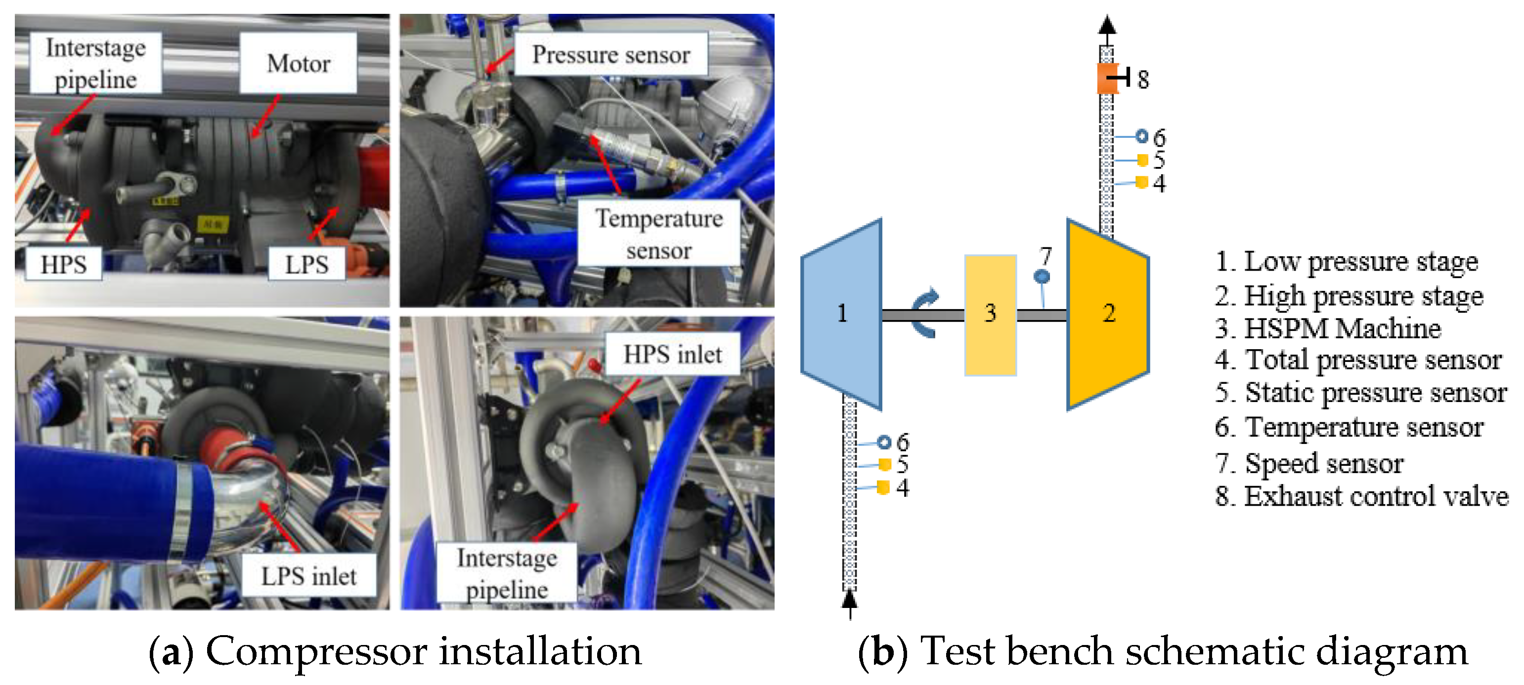
In order to verify the effectiveness of the numerical methods, the performance test of the research model (EPC model) was carried out in the laboratory of turbo machinery of a northeastern university. In this test, the precision of temperature sensors is ±0.1%. Pressure measurements are done by piezoresistive sensors with a precision of ±0.3%. The rotor speed is measured by an external magnetic induction tachometer with a precision of ±0.2%. To better simulate the actual HFC intake condition, a 90° bend was installed at the LPS inlet. In the experiment, the MFR, pressure and temperature data are collected by setting sensors at the inlet and outlet of the compressor, thus, the isentropic efficiency and the pressure ratio of the compressor can be calculated. The arrangement of compressor to be tested, sensors and interstage pipelines are shown in Figure 4a, and the test principle is shown in the Figure 4b.
In order to eliminate the influence of the intake temperature on the performance of the compressor, the reduced parameters were used to characterize the compressor performance in which all the parameters are reduced to standard atmospheric pressure and 298 K. The formulas for calculating the reduced parameters are as follows:
where Mcor is reduced mass flow rate; Mc is the actual mass flow rate; Ncor is reduced speed and nc is the actual speed; P1 is the absolute total pressure of compressor inlet; T1 is the total temperature of compressor inlet.
The pressure ratio and isentropic efficiency can be calculated by the following formulas:
where π is the pressure ratio; η is the isentropic efficiency; K is the isentropic exponent and its value is 1.4; P2 is the absolute total pressure of compressor outlet; T2 is the total temperature of compressor outlet.
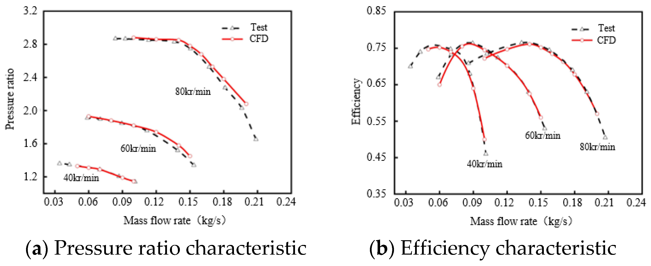
The compressor performance test and CFD calculations were both carried out at three speeds in this work to verify the effectiveness of the numerical methods. Figure 5 compares the performance curves between CFD and test results at the speed of 40 kr/min, 60 kr/min and 80 kr/min, respectively. It can be seen form Figure 5a,b that at low speed, the test and CFD results can match well with each other on both the pressure ratio and the efficiency curves; while with the speed increases, the deviation between the CFD and the test results is also growing. At 80 kr/min, the difference in pressure ratio and efficiency between CFD and the test were 1% and 2%, respectively, and it can be seen clearly that the test results are higher than that of the CFD results in both the pressure ratio and efficiency. The main reason for the difference is that the heat transfer of the volute is not considered during the CFD calculation, while in the tests, the volute dissipates heat outward, which will undoubtedly reduce the isentropic compression work and improve the test efficiency. In addition, in the actual work of the compressor, the rotor will expand due to the rise of temperature, thus reducing the distance between the impeller and the volute and mitigating the clearance leakage flow loss. In general, the results of the test and CFD are well matched, which verifies the effectiveness of the numerical method adopted in this work.
3. Results and Discussions
3.1. Characteristic Curve Analysis of Three Compressors
Figure 6 shows the CFD results of the compressor with three kinds of interstage pipes at 40 kr/min, 60 kr/min and 80 kr/min. It can be seen from Figure 6a that the pressure ratio of the EPC model is the minimum with the increase of the MFR under the three rotational speeds; the value of TPC model is between the EPC and the SPC model; and this trend is more obvious with the increase of the compressor speed. At the work condition of 130% MFR, the pressure ratio of EPC model is reduced by about 8% and 6% compared with the SPC and TPC model, respectively. It can be seen from Figure 6b that the efficiency curves of the three models are consistent with the pressure ratio curves at three rotational speeds. Thus, it can be concluded that the inner diameter of the bend section of the interstage pipeline has a more obvious influence on the compressor performance than that of the straight section. At 130% MFR condition, the efficiency of EPC model is reduced by about 2 and 1.5 percentage points compared with SPC and TPC model, respectively.
The above phenomenon shows that the shape of the interstage pipeline has a great influence on the performance of the compressor. When the straight pipe is used as a diffuser channel, the MFR decreases, and the pressure ratio increases after the air is pressurized through the straight pipe. When the air passes through the bend section with a uniform inner diameter, it tends to move outwardly due to the influence of the centrifugal force, leading to a greater static pressure on the outside of the bend section; while, when the bend section is used as a diffuser channel, the air flows through the straight section at a constant speed and pressure, and the flow velocity is larger than that of the model of the straight section with a uniformly increasing inner diameter. When the air flow passes through the bend section, it will generate a large centrifugal force thus making the flow more complicated, resulting in poor performance. There are obvious differences in the performance results of the three models, reflecting the influence of interstage pipelines on compressor performance.
3.2. Analysis of Flow Field in Interstage Pipelines of Compressors
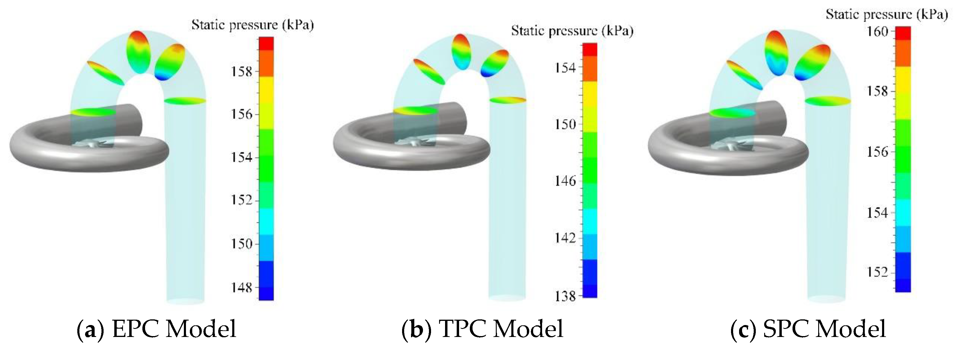
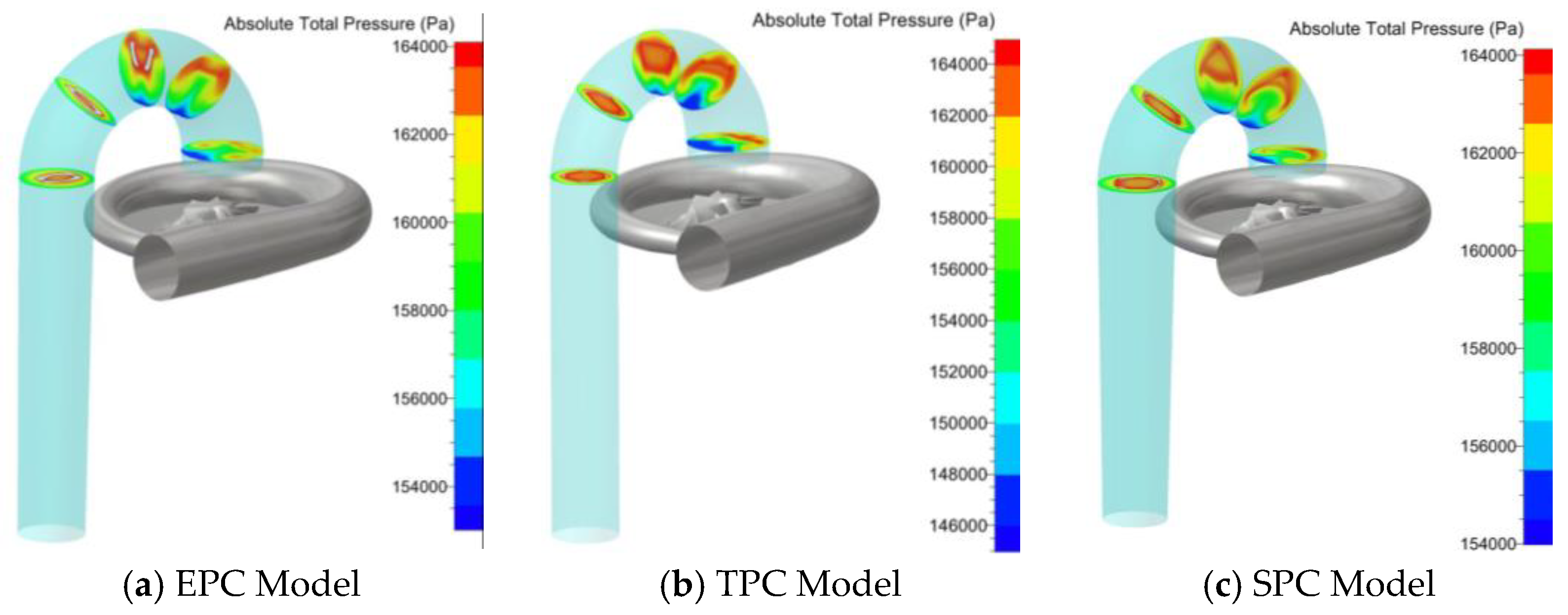
Figure 7 and Figure 8 show the static pressure and total pressure distribution in the interstage pipe, respectively. As can be seen from Figure 7, there are obvious differences in the static pressure at different sections of each pipeline, and the static pressure distribution at the inlet and outlet of the bend is relatively uniform. Due to the stabilizing effect, the unsteady flow induced by the LPS is improved when the gas flows through the straight section. However, in the bend section, the obvious static pressure changes caused by the centrifugal force can be seen clearly. From Figure 8 it can be seen that the total pressure distribution of the three models is significantly different. The total pressure in the straight section of the EPC model is higher than that in the SPC and TPC models, but when the air flows from the bend to the HPS inlet, the total pressure amplitude gradually decreases at each section compared with the other two models, which indicates that the loss in the interstage pipeline of the EPC model mainly occurs in the bend section.
The comparative analysis of the three models shows that the high total pressure area in the interstage pipeline is located above the bend section, while below the bend section, the vortex induced by centrifugal force results in a low-pressure area. Therefore, the flow loss in the interstage pipeline mainly occurs in the lower part of the bend section. The SPC model has the smallest range of the low-pressure zone, so the total pressure distortion at the inlet of the HPS impeller is also the smallest.
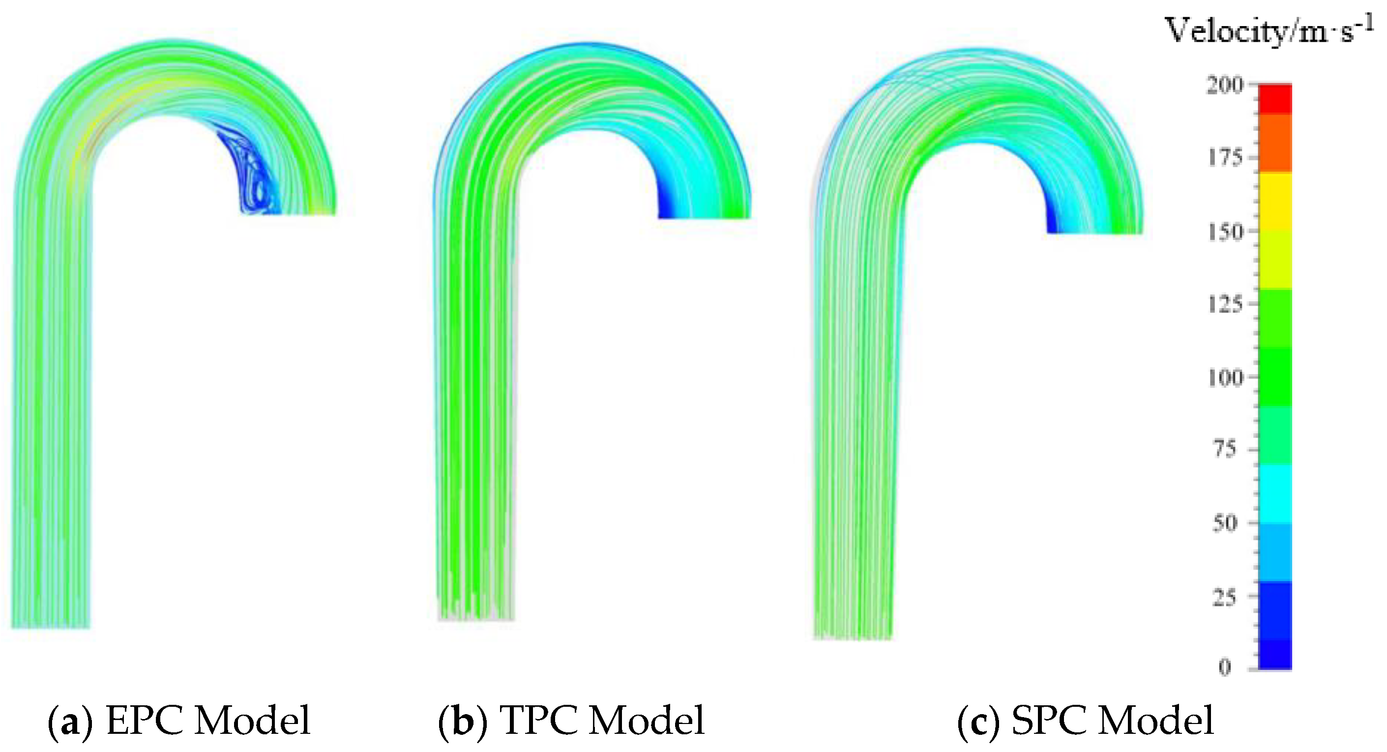
Figure 9 shows the streamline distribution on the middle height of the interstage pipeline of the three models. It can be seen that after the airflow enters the bend section, the streamline is shifted to the outer wall of the pipe under the action of centrifugal force and wall viscosity. From the EPC model in Figure 9a, it can be seen that the inside of the bend produces obvious low speed vortex, and the flow state at the outlet section of the interstage pipeline is relatively severe. While, form Figure 9c it is found that the streamline in the SPC model is more uniform, and the low speed vortex inside the bend section is smallest compared with the other two models.
By comparing the velocities of the three models, it can be seen that the model with fast airflow acceleration in the bend section will induce large vortex and high strength total pressure distortion. On the contrary, the model with slow airflow acceleration has better total pressure distortion and internal flow field distribution. In the bend section, compared with SPC and TPC models, the EPC model produces stronger secondary flow and the distortion will inevitably affect the impeller.
3.3. Analysis of Flow Field in Rotor
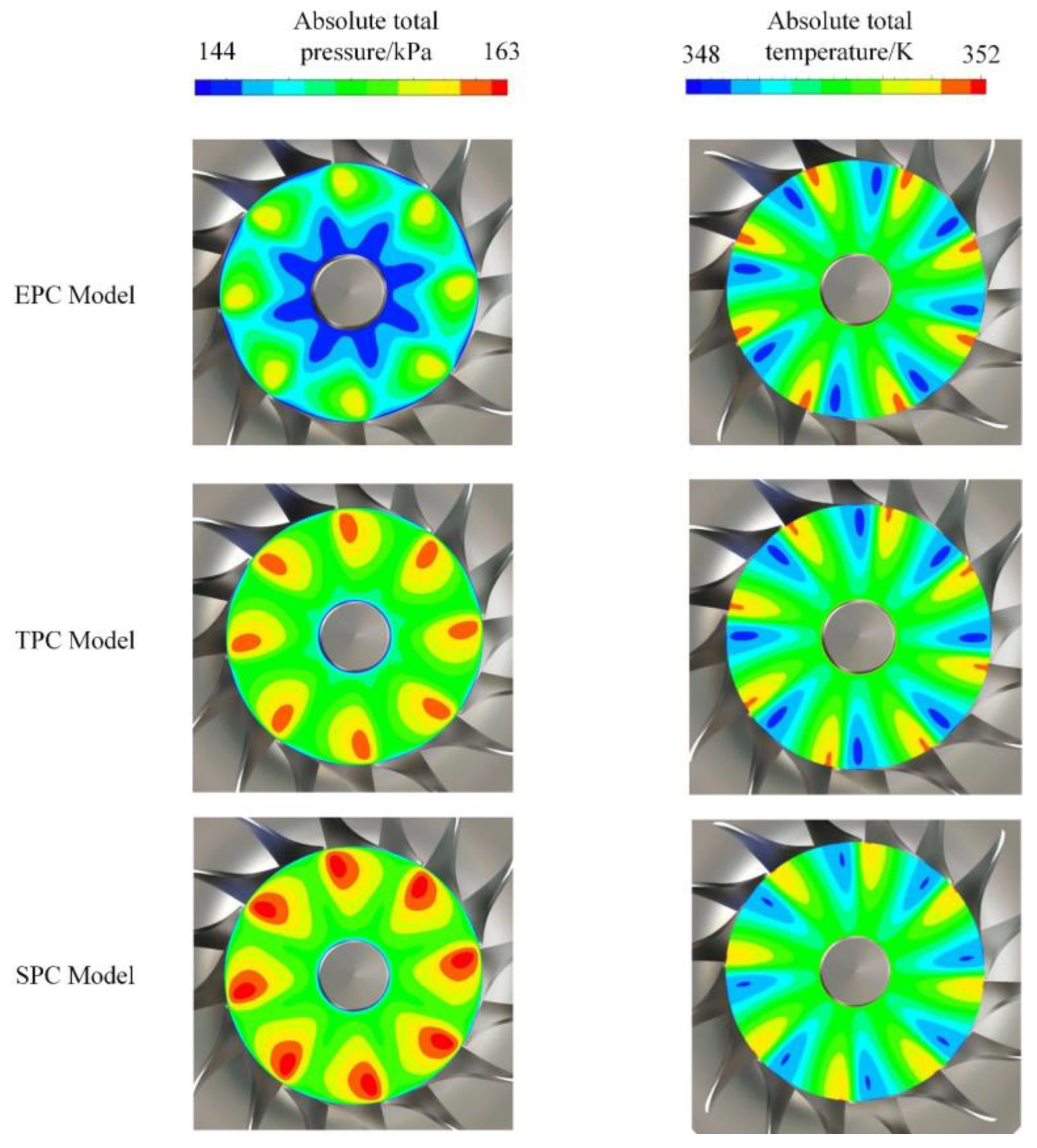
When the air flow reaches the exit of the bend section of the interstage pipeline, the axial velocity corresponding to the total pressure distortion area decreases obviously. The flow field difference at the inlet of the impeller caused by the bend pipe will inevitably affect the flow state inside the impeller. Figure 10 shows the circumferential total pressure and total temperature distribution at the inlet section of the impeller of the three models. It can be seen that the high-pressure region of the three models is located between the main blade and the splitter blade, and the extreme value region is close to the leading edge of the main blade and distributed along 50% blade height to the tip. On the suction side of the blade near the root, a low-pressure area is generated, which is mainly affected by the flow of the bend pipe. Comparative analysis shows that the SPC model has higher circumferential total pressure at the impeller entrance than the other two models, and the EPC model has the smallest high-pressure zone.
It can be seen more intuitively from the total temperature nephogram of the three models that a high temperature area is formed on the suction surface side of the main blade, which corresponds to the high-pressure area in the total pressure nephogram. It is found that the high-pressure zone formed in the SPC model at the leading edge of the main blade is larger than that of the other two models, while the high-temperature zone is smaller than that of the other two models, which indicates that the SPC model has the smallest flow loss at the impeller inlet, while the EPC model has the highest flow loss, which is consistent with the law corresponding to the total pressure cloud map of the intermediate pipeline mentioned above.
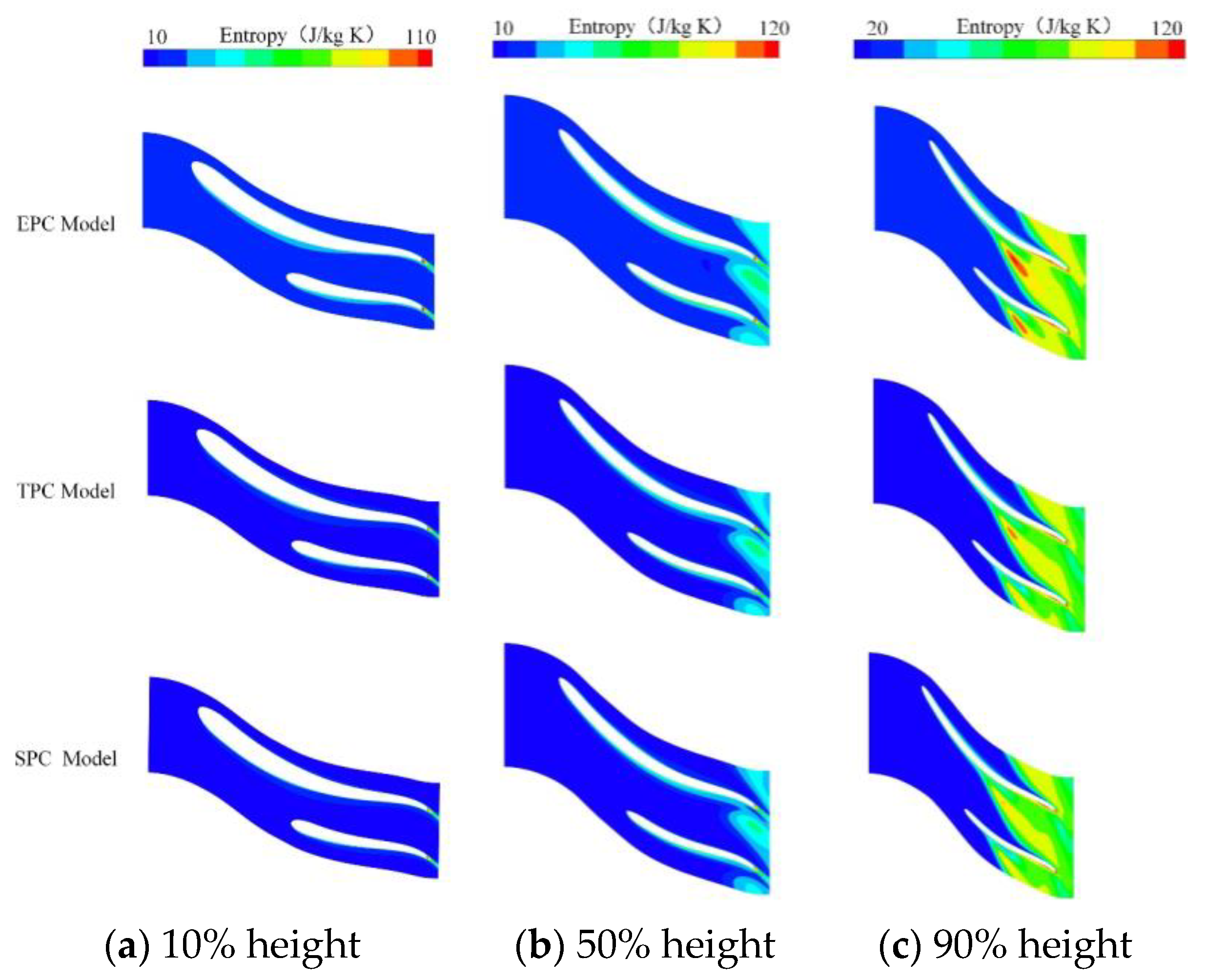
Figure 11 shows the entropy distribution of the three models at 10%, 50% and 90% blade heights. It can be seen from the analysis that the entropy of the three models at different blade heights show the same change pattern. At 90% blade height, a leakage vortex formed on the suction surface of the blade and caused significant flow loss. Compared to flow losses that occur at other locations, the entropy increase caused by the leakage flow loss is the most significant, which becomes the main source of flow loss. By comparing the three models, it can be seen that the EPC model with the stronger total pressure distortion has the greatest loss at this position, while the SPC model with the smallest total pressure distortion has the least flow loss. In addition, the entropy mutation region caused by the wake can be seen at the trailing edge of the blade. The loss at 50% blade height is mainly caused by the tip leakage flow combined with the wake loss, but the value decreases compared with the high entropy area at 90% blade height. At 10% blade, the entropy increases and mutation area caused by the leakage vortex has disappeared, and the wake is the main cause of the flow loss. From the entropy distribution at different blade heights, it can be seen that from the leading edge to the trailing edge, the loss caused by leakage vortex accounts for a relatively large proportion, and the wake loss is small. The blade clearance leakage coupled with intake distortion becomes the main source of loss.
By comparing the entropy values of the three models in Figure 11, it is found that at 90% blade height, the high entropy area of EPC model is more prominent than that of TPC and SPC model, and the SPC model has the lowest entropy. It can be seen that the change of the pipe’s inner diameter has a significant impact on the flow loss along the blade height: the more uniform the inner diameter of the bend section, the smaller the leakage loss. At 50% blade height, the entropy distribution is the same as the 90% blade height. The area of entropy increase caused by leakage vortex decreases and the flow field becomes more stable. In general, the change of pipe inner diameter has a great influence on the leakage vortex generated on the suction surface of the blade: the higher the total pressure distortion in the bend section, the greater the loss caused by blade clearance leakage flow.
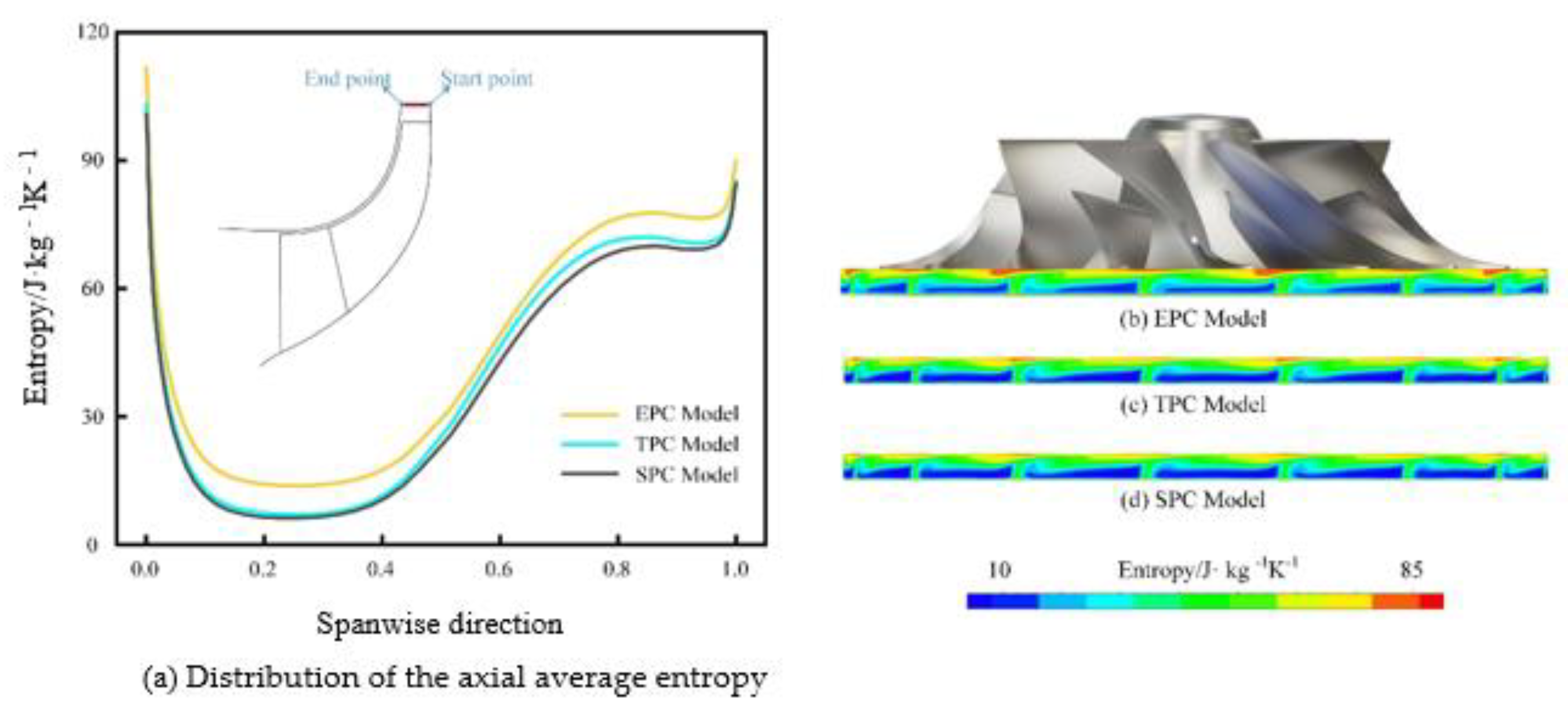
Figure 12a shows the distribution of the axial average entropy values of the three models. It can be clearly seen that the average entropy values from hub to shroud show a trend of decreasing and then increasing, with the entropy values plummeting in the 0–10% span and gradually increasing in the 40–80% span. Among the three models, the EPC model has a higher overall entropy span; the SPC model has the lowest entropy value; and the TPC model has a smaller difference in value from the SPC model. Therefore, a pipe with uniform inner diameter can significantly improve the entropy distribution in the axial direction at the impeller outlet.
Figure 12b–d shows the circumferential distribution of entropy values at the impeller exit for the three models. It can be seen that the high entropy area of the three models is located at the top of the trailing edge of the impeller, which is caused by the leakage vortex of the blade; the entropy value of the area corresponding to the blade wake is higher than that of the other areas at the same cross-section. The entropy value of the SPC model is more uniformly distributed and suffers the least leakage and wake loss, which is consistent with the results of the previous analysis.
3.4. Load Analysis of Compressor Blade
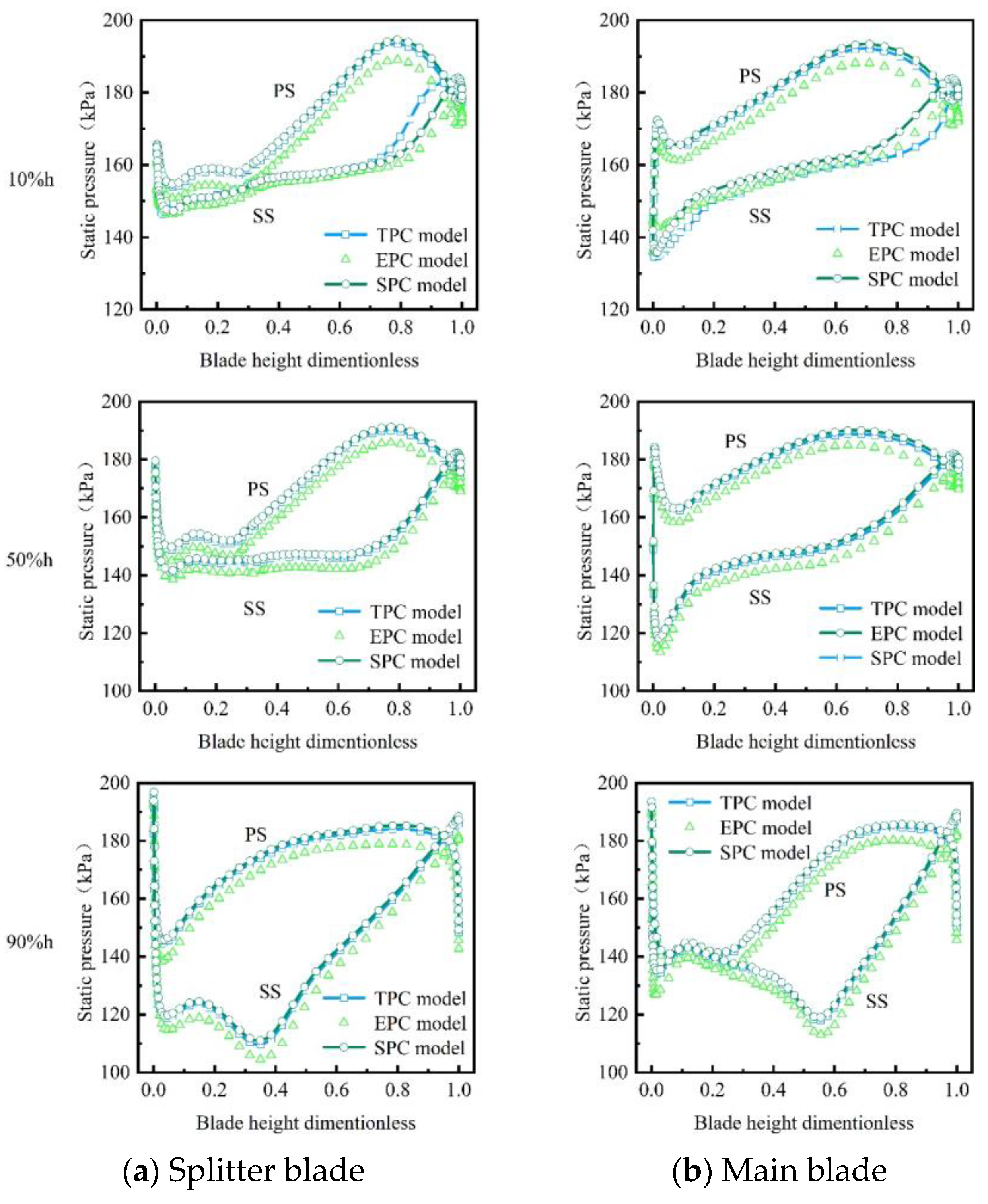
Figure 13a,b show the static pressure distribution of the splitter blade and the main blade at different blade heights of the three models, respectively. The pressure difference between the blade pressure and the suction surface can be used to determine the relationship between the load to a certain extent. From Figure 13a it can be seen that at the position of 10% blade height, the static pressure of the pressure surface of the three models changes more evenly. Compared with the other two models in Figure 13b, the static pressure of the suction surface of EPC model increases first and then decreases from the leading edge to the trailing edge, and the load of the main blade appears the maximum value at the point of 0.8 chord, while the SPC model has a stronger trend of load reduction than the other two models. The load difference of the three types of pipelines is the largest at the 0.8 chord length for the splitter blade, as shown in Figure 13a, where the load reduction of the TPC model is the most obvious. The load distribution on the suction surface and pressure surface of the three models is significantly different at the trailing edge, which is caused by the leakage vortex loss. Combined with the entropy diagram of 10% blade height in Figure 12, it is known that the EPC model has a high entropy on the pressure surface, which can also be seen in the pressure distribution in 10% blade height.
At 50% blade height, the load on the main blade and the splitter blade increases compared with that on the 10% blade height, which has the similar variation rules in the three models. At 90% blade height, the load extremum of the splitter blade migrates to 0.35 chord length, and that of the main blade migrates to 0.6 chord length. On the whole, the difference of inner diameter of interstage pipe has greater influence on blade root rather than blade tip.
4. Experimental Verification of Three Models
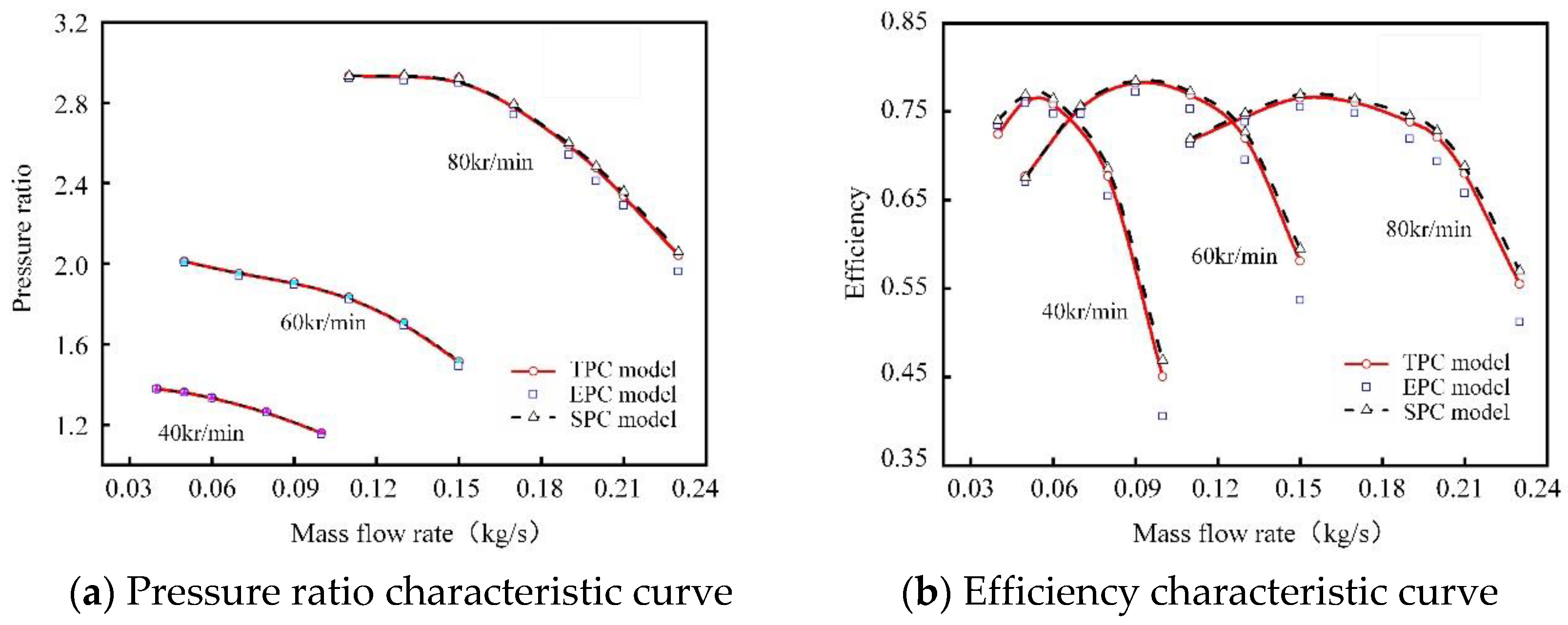
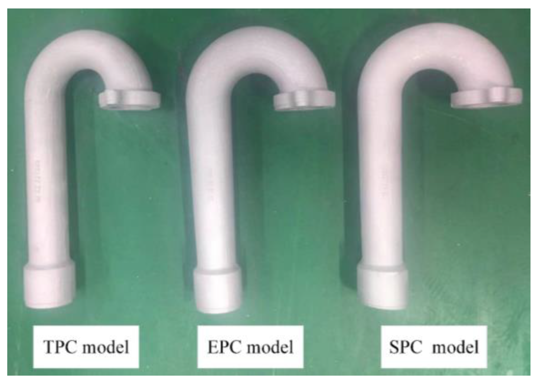
According to the previous analysis, it is known that the three types of pipes have a significant impact on the performance of the compressor, and the SPC model shows a superior performance. In order to verify the performance of the interstage pipelines presented in this paper, the three models were cast in the way of fast vanishing mold and assembled on the same air compressor for test verification, as shown in Figure 14.
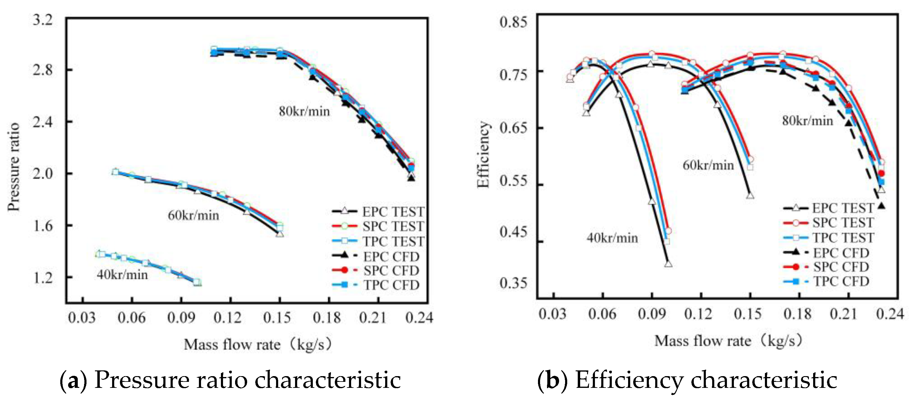
Figure 15 shows the test and CFD (only at 80 kr/min) results for the three models at 40 kr/min, 60 kr/min and 80 kr/min. In the overall view, the efficiency and pressure ratio of the SPC model are better than the other two types of models, and the EPC model shows the worst performance; under the high speed (80 kr/min) condition, this difference is more obvious with the increase of the MFR, and the efficiency of the EPC model is reduced by up to 2 percentage points compared with the SPC model. Therefore, we suggest that in the design of two-stage centrifugal compressor, the SPC model should be preferred in the design of the interstage pipeline, so as to improve the efficiency of the air compressor.
5. Conclusions
In this work, a two-stage centrifugal compressor with three types of interstage pipelines used in a 120 kW HFC were analyzed using experiments and CFD methods. The internal flow field of the interstage pipeline, the overall efficiency of the compressor with different interstage pipelines, as well as the influence of bend section on the inlet distortion of downstream HPS were analyzed. The main conclusions are as follows:
(1) Due to the influence of the bend section, the EPC model leads to strong distortion at the inlet of the HPS impeller, resulting in overall performance degradation. Affected by centrifugal force and wall viscosity, obvious secondary flow is generated in the bend section of the EPC model. Near the bend outlet, the SPC model has more uniform distribution and smaller total pressure distortion, compared with that of the EPC and TPC model. The high entropy area of the three models is located at the top of the trailing edge of the impeller, which is caused by the leakage vortex of the blade.
(2) The inner diameter uniformity of the bend section will affect the flow stability and total pressure loss of the interstage pipeline. The more uniform the inner diameter of the bend section, the wider the high total pressure area, and the smaller the corresponding pressure loss. For the flow in impeller, as the blade height gradually decreases, the influence of the leakage vortex gradually weakens. On the main blade, the load becomes more uniform with the decrease of blade height; while for the splitter blade, the load extremum migrates to the trailing edge with the decrease of blade height.
(3) The experimental and CFD results show that among the three models, the EPC model induces the most intense total pressure distortion at the condition of 80 kr/min and 130% mass flow rate, resulting in an efficiency reduction of 2 and 1.5 percentage points compared with the SPC and the TPC model, respectively. The efficiency and pressure ratio of the SPC model are the best among the three models.Thus, it is recommended that the interstage pipelines similar to SPC models should be recommended in the design of two-stage centrifugal compressor.
Author Contributions
Conceptualization, methodology, software, validation, D.Y.; formal analysis, investigation, D.Y. and H.W.; resources, H.W.; data curation, H.Z.; writing—original draft preparation, Q.Z.; writing—review and editing, D.Y.; visualization, Q.Z.; supervision, Z.Z.; project administration, D.Y. All authors have read and agreed to the published version of the manuscript.
Funding
This work was financially supported by the National Natural Science Foundation of China grant number 52006027 and the Natural Science Foundation of Hebei Province grant number E2021501028 and the Central University Basic Scientific Research Business Fee Funding Project grant number N2123027.
Institutional Review Board Statement
Not applicable.
Informed Consent Statement
Not applicable.
Data Availability Statement
Not applicable.
Conflicts of Interest
The authors declare no conflict of interest.
Nomenclature
| HFC | Hydrogen fuel cell |
| CFD | Computational Fluid Dynamics |
| HPS | HPS |
| LPS | LPS |
| S-A | Spalart-Allmaras |
| MFR | Mass flow rate |
| η | Efficiency |
| Mcor | Reduced mass flow rate |
| Mc | Actual mass flow rate |
| Ncor | Reduced speed |
| nc | Actual speed |
| P1 | Absolute total pressure of compressor inlet |
| π | pressure ratio |
| T1 | Total temperature of compressor inlet |
| P2 | Absolute total pressure of compressor outlet |
| T2 | Total temperature of compressor outlet |
References
- Park, S.; Shao, Y.; Wan, H.; Viswanathan, V.V.; Towne, S.A.; Rieke, P.C.; Liu, J.; Wang, Y. Degradation of the ionic pathway in a pem fuel cell cathode. J. Phys. Chem. C 2011, 115, 22633–22639. [Google Scholar] [CrossRef]
- Dutta, S.; Shimpalee, S.; Zee, J. Numerical prediction of mass-exchange between cathode and anode channels in a PEM fuel cell. Int. J. Heat Mass Transf. 2001, 44, 2029–2042. [Google Scholar] [CrossRef]
- Liu, X.; Tao, W.; Li, Z. Three-dimensional transport model of PEM fuel cell with straight flow channels. J. Power Sources 2006, 158, 25–35. [Google Scholar] [CrossRef]
- Hassanzadeh, H.; Li, X.; Baschuk, J.J.; Mansouri, S.H. Numerical simulation of laminar flow development with heat and mass transfer in pem fuel cell flow channels having oxygen and hydrogen suction at one channel wall. Int. J. Energy Res. 2011, 35, 670–689. [Google Scholar] [CrossRef]
- Hashemi-Valikboni, S.Z.; Ajarostaghi, S.S.M.; Delavar, M.A.; Sedighi, K. Numerical prediction of humidification process in planar porous membrane humidifier of a pem fuel cell system to evaluate the effects of operating and geometrical parameters. J. Therm. Anal. Calorim. 2020, 141, 1687–1701. [Google Scholar] [CrossRef]
- Khazaee, I.; Ghazikhani, M. Numerical simulation and experimental comparison of channel geometry on performance of a pem fuel cell. Arab. J. Sci. Eng. 2012, 37, 2297–2309. [Google Scholar] [CrossRef]
- Han, J.; Yu, S.; Yi, S. Adaptive control for robust air flow management in an automotive fuel cell system. Appl. Energy 2017, 190, 73–83. [Google Scholar] [CrossRef]
- Ou, K.; Wang, Y.; Li, Z.; Shen, Y. Feedforward fuzzy-PID control for air flow regulation of PEM fuel cell system. Int. J. Hydrog. Energy 2015, 40, 11686–11695. [Google Scholar] [CrossRef]
- Bizon, N. Tracking the maximum efficiency point for the FC system based on extremum seeking scheme to control the air flow. Appl. Energy 2014, 129, 147–157. [Google Scholar] [CrossRef]
- Zhao, D.; Zheng, Q.; Gao, F.; Bouquain, D.; Dou, M.; Miraoui, A. Disturbance decoupling control of an ultra-high speed centrifugal compressor for the air management of fuel cell systems. Int. J. Hydrog. Energy 2014, 39, 1788–1798. [Google Scholar] [CrossRef]
- Zhao, B.; Sun, H.; Shi, X.; Qi, M.; Guo, S. Investigation of using multi-shockwave system instead of single normal shock for improving radial inflow turbine reliability. Int. J. Heat Fluid Flow 2018, 71, 170–178. [Google Scholar] [CrossRef] [Green Version]
- Galindo, J.; Fajardo, P.; Navarro, R.; García-Cuevas, L.M. Characterization of a radial turbocharger turbine in pulsating flow by means of CFD and its application to engine modeling. Appl. Energy 2013, 103, 116–127. [Google Scholar] [CrossRef]
- Walkingshaw, J.; Spence, S.; Ehrhard, J.; Thornhill, D. An experimental assessment of the effects of stator vane tip clearance location and back swept blading on an automotive variable geometry turbocharger. J. Turbomach. 2014, 136, 927–937. [Google Scholar] [CrossRef]
- Yang, D.; Yang, C.; Lao, D.; Zeng, T. A detailed investigation of a variable nozzle turbine with novel forepart rotation guide vane. J. Automob. Eng. 2019, 233, 994–1007. [Google Scholar] [CrossRef]
- Zhao, D.; Xu, L.; Huangfu, Y.; Dou, M.; Liu, J. Semi-physical modeling and control of a centrifugal compressor for the air feeding of a pem fuel cell. Energy Convers. Manag. 2017, 154, 380–386. [Google Scholar] [CrossRef]
- Gelfi, S.; Stefanopoulou, A.G.; Pukrushpan, J.T.; Peng, H. Dynamics of Low-Pressure and High-Pressure Fuel Cell Air Supply Systems. In Proceedings of the American Control Conference, Denver, CO, USA, 4–6 June 2003; Volume 3, pp. 2049–2054. [Google Scholar]
- Zheng, X.; Zhang, Y.; He, H.; Qiu, Z. Design of a centrifugal compressor with low specific speed for automotive fuel cell. Am. Soc. Mech. Eng. 2008, 1531–1536. [Google Scholar]
- Yz, A.; Sx, A.; Yu, W. Performance improvement of centrifugal compressors for fuel cell vehicles using the aerodynamic optimization and data mining methods. Int. J. Hydrog. Energy 2020, 45, 11276–11286. [Google Scholar]
- Chen, H.; Zhuge, W.; Zhang, Y.; Ma, X.; Tao, L. Performance improvement of a centrifugal compressor for the fuel cell vehicle by tip leakage vortex control. J. Therm. Sci. 2021, 30, 2099–2111. [Google Scholar] [CrossRef]
- Mizuki, S.; Asaga, Y.; Ono, Y.; Tsujita, H. Investigation of surge behavior in a micro centrifugal compressor. J. Therm. Sci. 2006, 15, 97–102. [Google Scholar] [CrossRef]
- Liu, Y.; Lao, D.; Yang, C.; Wang, L.; Li, D. Aerodynamic Excitation and Forced Response of Centrifugal Compressor Impeller in Inlet Distortion. In Proceedings of the ASME Turbo Expo 2015, Montreal, QC, Canada, 15–19 June 2015. No. GT2015-42201. [Google Scholar]
- Zhang, M.; Hou, A.; Wang, Q. Numerical investigation of blade vibration response induced by inlet distortion in axial compressor. J. Propuls. Technol. 2011, 32, 466–470+503. [Google Scholar]
- Han, G.; Lu, X.; Zhao, S.; Yang, C.; Zhu, J. Parametric studies of pipe diffuser on performance of a highly loaded centrifugal compressor. J. Eng. Gas Turbines Power Trans. ASME 2014, 136, 122604. [Google Scholar] [CrossRef]
- Sheoran, Y.; Bouldin, B. A Versatile Design of a Controlled Swirl Distortion Generator for Testing Gas Turbine Engines. In Proceedings of the ASME Turbo Expo 2008: Power for Land, Sea, and Air, Berlin, Germany, 9–13 June 2008; pp. 81–92. [Google Scholar]
- Ariga, I.; Kasai, N.; Masuda, S.; Watanabe, Y.; Watanabe, I. The effect of inlet distortion on the performance characteristics of a centrifugal compressor. J. Eng. Power 1983, 105, 223. [Google Scholar] [CrossRef]
- Zemp, A.; Kammerer, A.; Abhari, R. Unsteady CFD Investigation on Inlet Distortion in a Centrifugal Compressor. In Proceedings of the ASME Turbo Expo 2008: Power for Land, Sea, and Air, Berlin, Germany, 9–13 June 2008; pp. 1909–1919. [Google Scholar]
- Brune, K.H.; Schiffer, H.P.; Christmann, R.; Gnewikow, M. Experimental Investigations of the Disturbed Inlet-Flow Structure Caused by Mixing Geometries and Its Influence on the Performance of a Turbocharger Centrifugal Compressor. In Proceedings of the ASME Turbo Expo 2009: Power for Land, Sea, and Air, Orlando, FL, USA, 8–12 June 2009; ASME: New York, NY, USA, 2009. GT2009-59534. pp. 1295–1304. [Google Scholar]
- Kim, Y.; Engeda, A.; Aungier, R.; Direnzi, G. The influence of inlet flow distortion on the performance of a centrifugal compressor and the development of an improved inlet using numerical simulations. J. Power Energy 2001, 215, 323–338. [Google Scholar] [CrossRef]
- Engeda, A.; Kim, Y.; Aungier, R.; Direnzi, G. The inlet flow structure of a centrifugal compressor stage and its influence on the compressor performance. J. Fluids Eng. 2003, 125, 779–785. [Google Scholar] [CrossRef]
- Kammerer, A.; Abhari, R.S. Blade forcing function and aerodynamic work measurements in a high speed centrifugal compressor with inlet distortion. J. Eng. Gas Turbines Power 2010, 132, 092504. [Google Scholar] [CrossRef]
- Dickmann, H.; Wimmel, T.; Szwedowicz, J. Unsteady Flow in a Turbocharger Centrifugal Compressor: 3D-CFD-Simulation and Numerical and Experimental Analysis of Impeller Blade Vibration. In Proceedings of the ASME Turbo Expo 2005: Power for Land, Sea, and Air, Reno, NV, USA, 6–9 June 2005; pp. 1309–1321. [Google Scholar]
- Dickmann, H.; Wimmel, T.; Szwedowicz, J. Unsteady Flow in a Turbocharger CENTRIFUGAL compressor: 3D-CFD Simulation, Impeller Blade Vibration and Vaned Diffuser-Volute Interaction. In Proceedings of the ASME Turbo Expo 2009: Power for Land, Sea, and Air, Orlando, FL, USA, 8–12 June 2009; pp. 1471–1485. [Google Scholar]
- Wang, L.; Yang, C.; Zhao, B.; Lao, D.; Ma, C.; Li, D. The change of the inlet geometry of a centrifugal compressor stage and its influence on the compressor performance. J. Therm. Sci. 2013, 22, 197–208. [Google Scholar] [CrossRef]
- Li, D.; Yang, C.; Zhou, M.; Zhu, Z.; Wang, H. Numerical and experimental research on different inlet configurations of high speed centrifugal compressor. Sci. China Technol. Sci. 2012, 55, 174–181. [Google Scholar] [CrossRef]
Figure 1.
Geometry of the research model.

Figure 2.
Three models of the interstage pipeline.

Figure 3.
Grid of the research model.

Figure 4.
Compressor installation and test bench schematic diagram.

Figure 5.
Test and CFD results of the research model.

Figure 6.
Performance comparison between three models.

Figure 7.
Static pressure distribution in the interstage pipeline.

Figure 8.
Total pressure distribution in the interstage pipeline.

Figure 9.
Flow field distribution of 50% section of interstage pipeline.

Figure 10.
Circumferential total pressure and total temperature at impeller inlet.

Figure 11.
Entropy distribution at 10%, 50% and 90% blade height of three models.

Figure 12.
Entropy distribution at impeller outlet of three models.

Figure 13.
Static pressure distribution at different height of the three models.

Figure 14.
Three kinds of interstage pipes.

Figure 15.
Experimental of three models at different rotational speeds.


Table 1.
Main geometry parameters of the research model.
| Parameters | LPS | HPS |
|---|---|---|
| Number of main blade | 8 | 8 |
| Number of splitter blade | 8 | 8 |
| Inlet diameter of impeller (mm) | 55 | 50 |
| Diffuser inlet diameter (mm) | 80 | 74 |
| Volute outlet diameter (mm) | 41 | 41 |
| Rotor tip clearance (mm) | 0.35 | 0.35 |
| Blade outlet angle (°) | 30 | 30 |
Table 2.
Gird independent verification of the research model.
| Gird Number | m (kg/s) | π | η |
|---|---|---|---|
| 6048565 | 0.15 | 2.801 | 0.7631 |
| 7426874 | 0.15 | 2.814 | 0.7665 |
| 8864795 | 0.15 | 2.816 | 0.7669 |
Disclaimer/Publisher’s Note: The statements, opinions and data contained in all publications are solely those of the individual author(s) and contributor(s) and not of MDPI and/or the editor(s). MDPI and/or the editor(s) disclaim responsibility for any injury to people or property resulting from any ideas, methods, instructions or products referred to in the content. |
© 2022 by the authors. Licensee MDPI, Basel, Switzerland. This article is an open access article distributed under the terms and conditions of the Creative Commons Attribution (CC BY) license (https://creativecommons.org/licenses/by/4.0/).
Share and Cite
MDPI and ACS Style
Wang, H.; Yang, D.; Zhu, Z.; Zhang, H.; Zhang, Q. Effect of Interstage Pipeline on the Performance of Two-Stage Centrifugal Compressors for Automotive Hydrogen Fuel Cells. Appl. Sci. 2023, 13, 503. https://doi.org/10.3390/app13010503
AMA Style
Wang H, Yang D, Zhu Z, Zhang H, Zhang Q. Effect of Interstage Pipeline on the Performance of Two-Stage Centrifugal Compressors for Automotive Hydrogen Fuel Cells. Applied Sciences. 2023; 13(1):503. https://doi.org/10.3390/app13010503
Chicago/Turabian StyleWang, Huaiyu, Dengfeng Yang, Zhengcan Zhu, Hongjie Zhang, and Qian Zhang. 2023. "Effect of Interstage Pipeline on the Performance of Two-Stage Centrifugal Compressors for Automotive Hydrogen Fuel Cells" Applied Sciences 13, no. 1: 503. https://doi.org/10.3390/app13010503
Note that from the first issue of 2016, this journal uses article numbers instead of page numbers. See further details here.