
Parametric Finite Element Study on FREEDAM Beam to Column Joints with Different Details of the Haunch Slotted Holes


Abstract
:1. Introduction
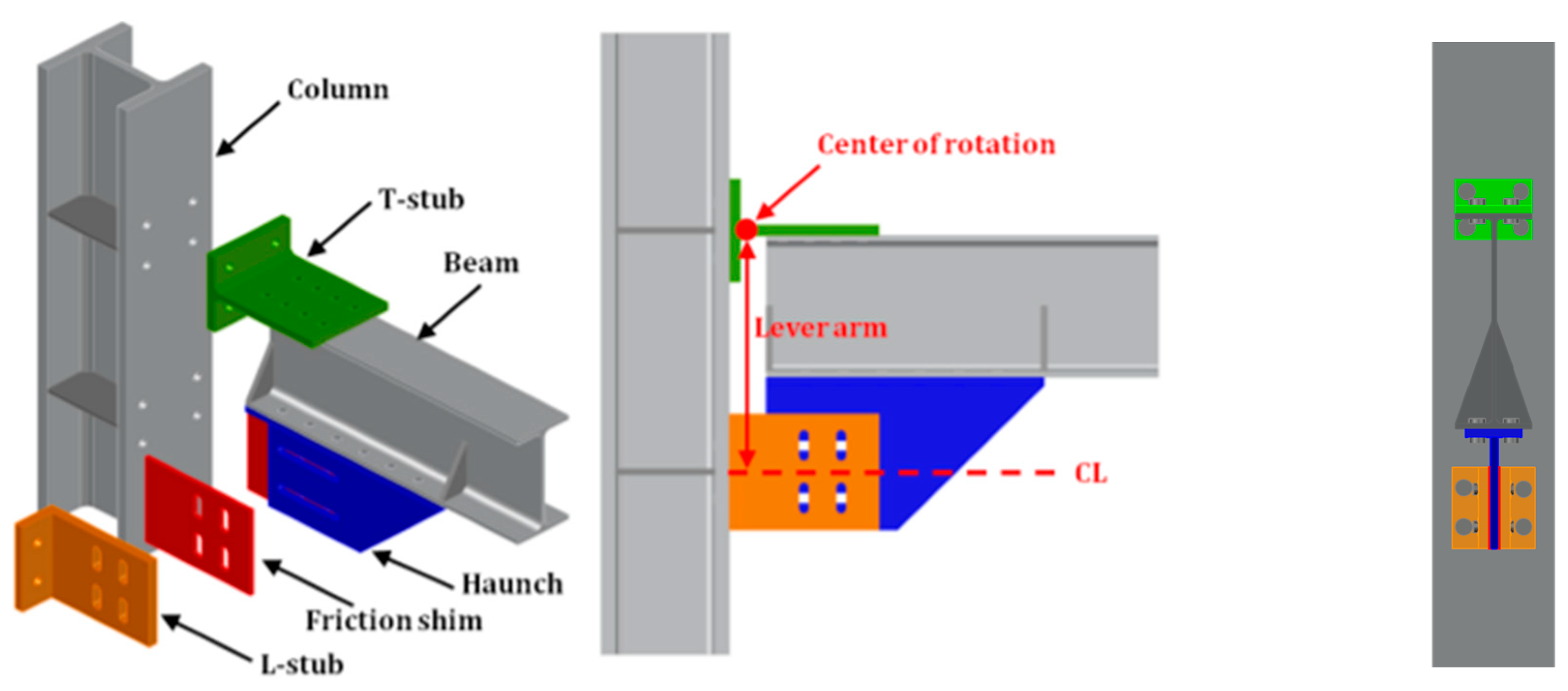
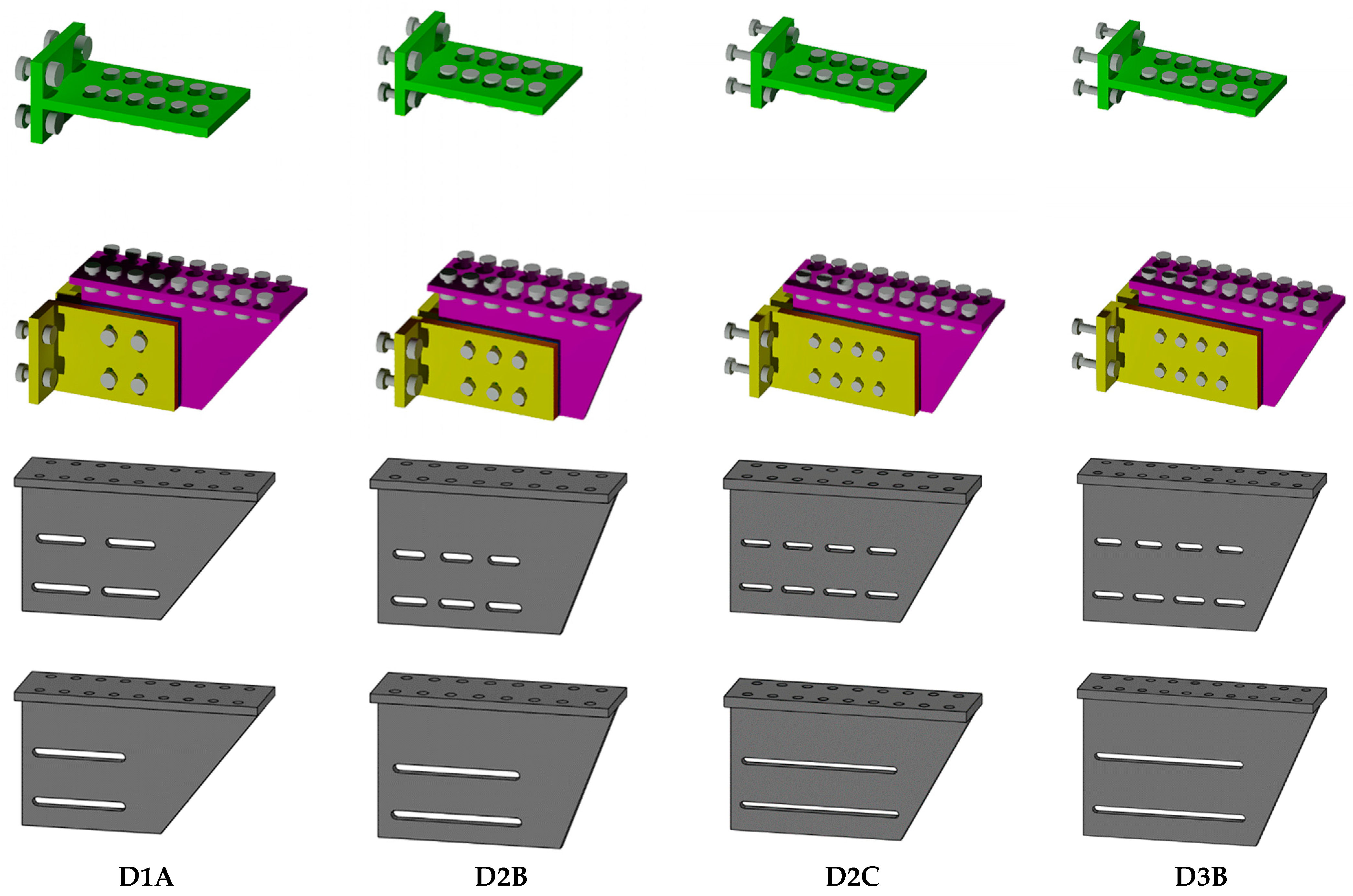
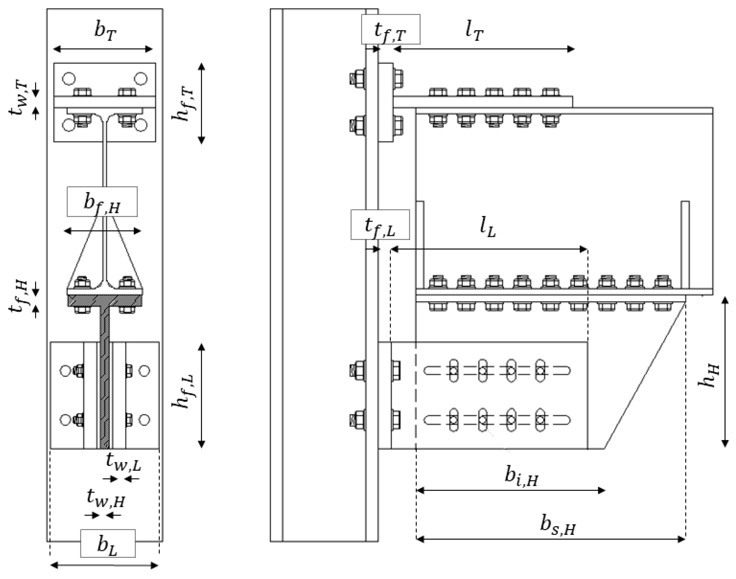
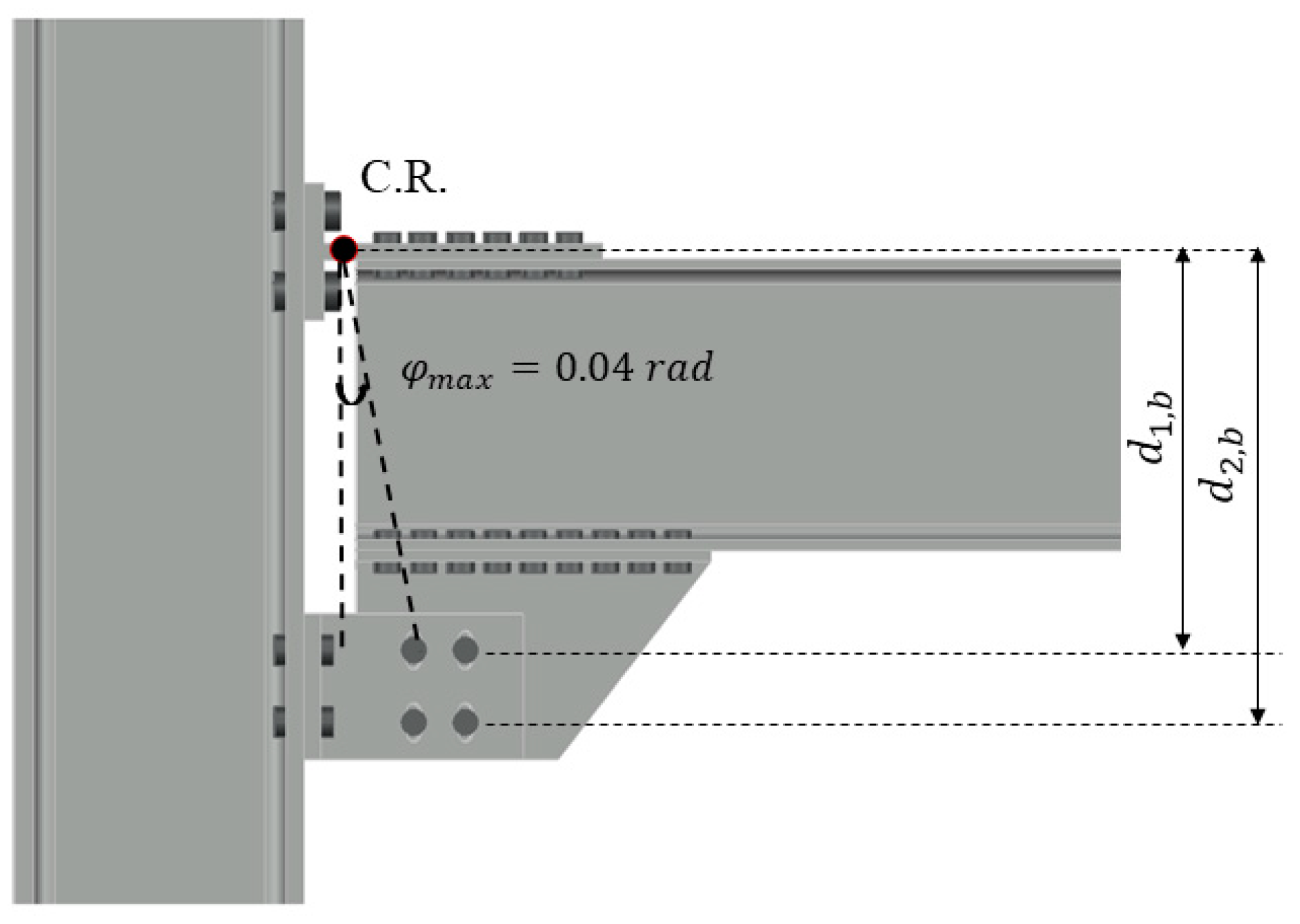
2. Description of the Investigated Joints and Relevant Damper Configurations
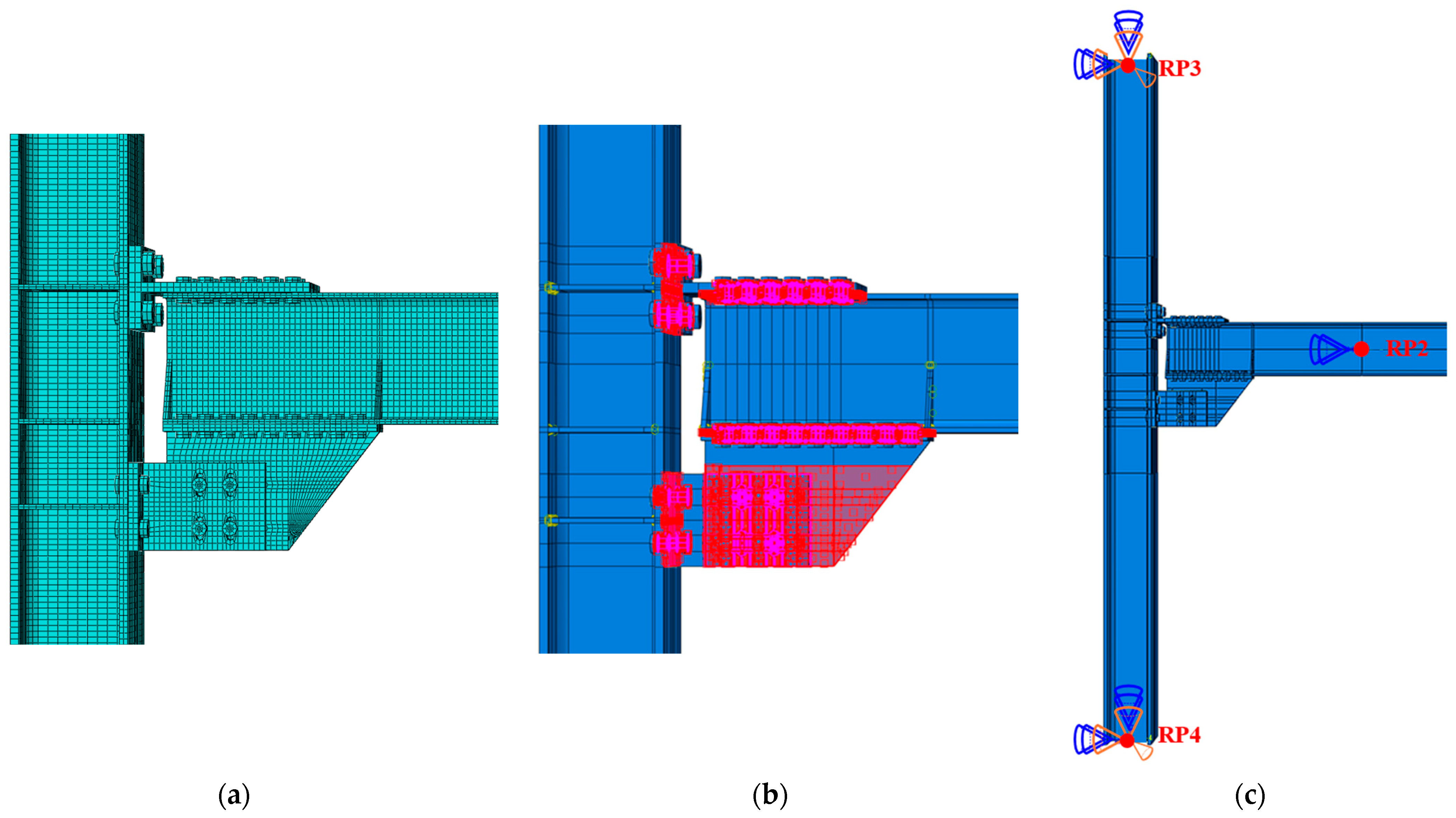
3. Finite Element Modeling
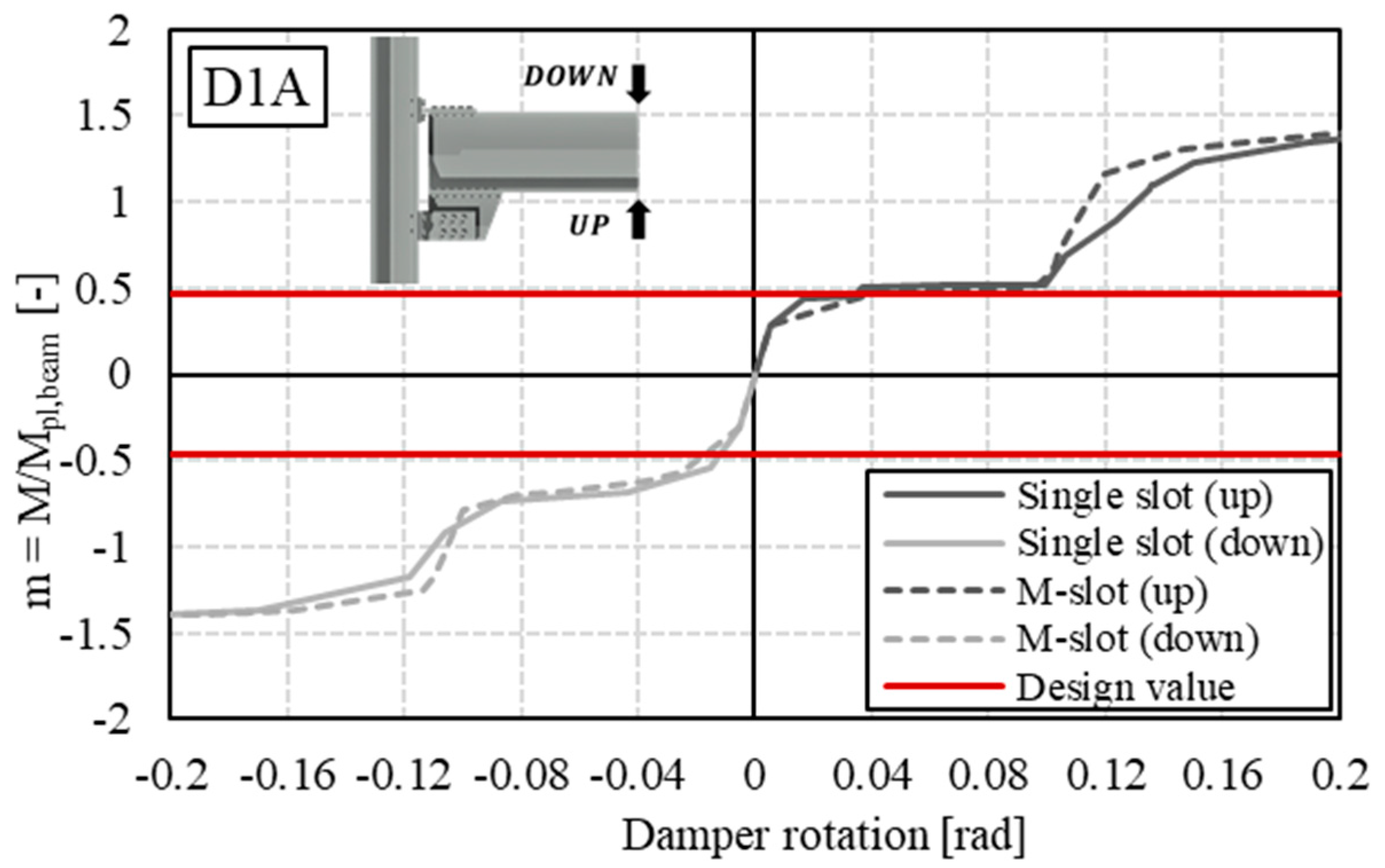
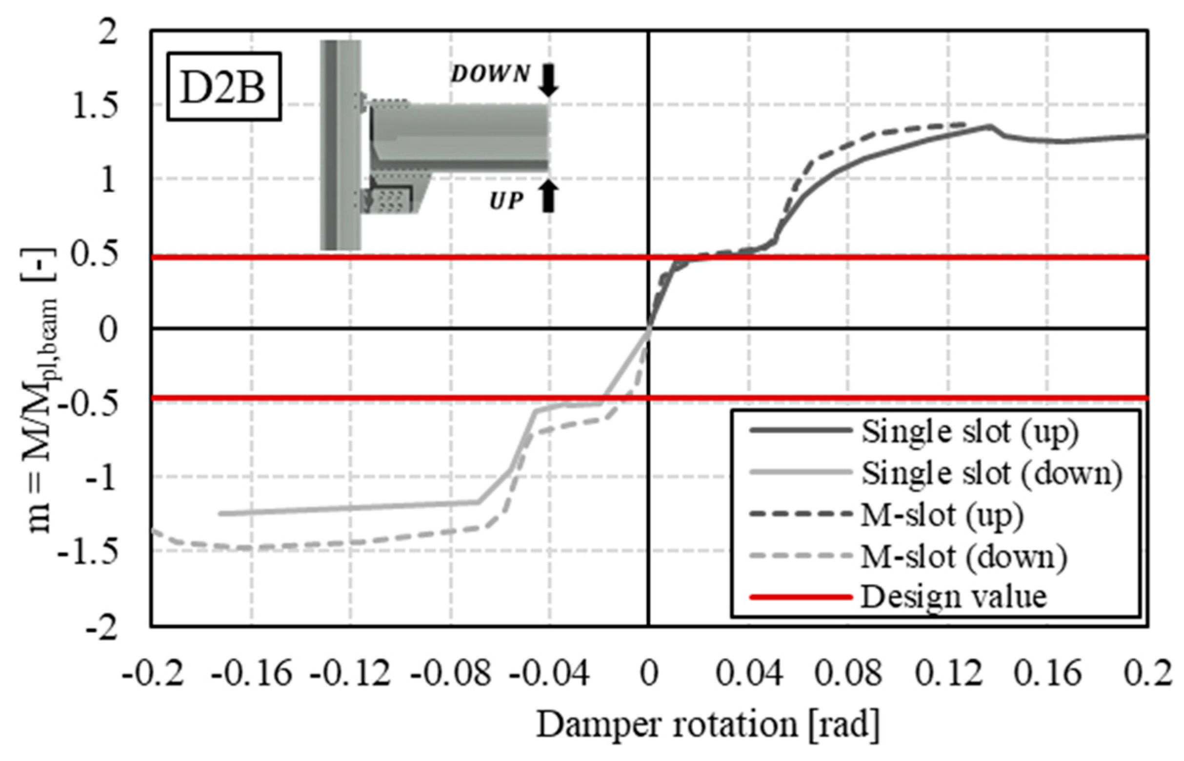
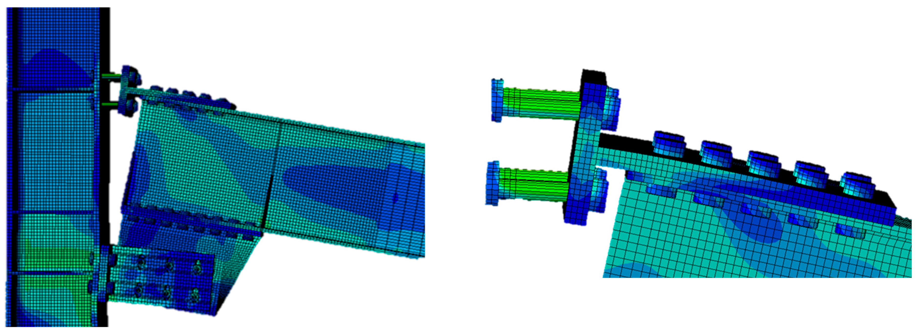
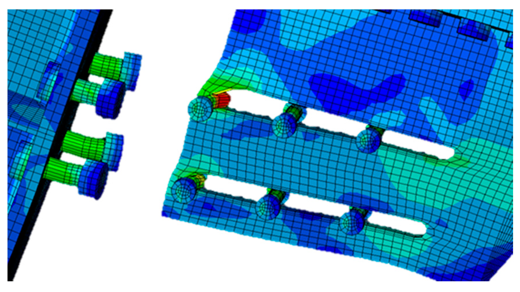
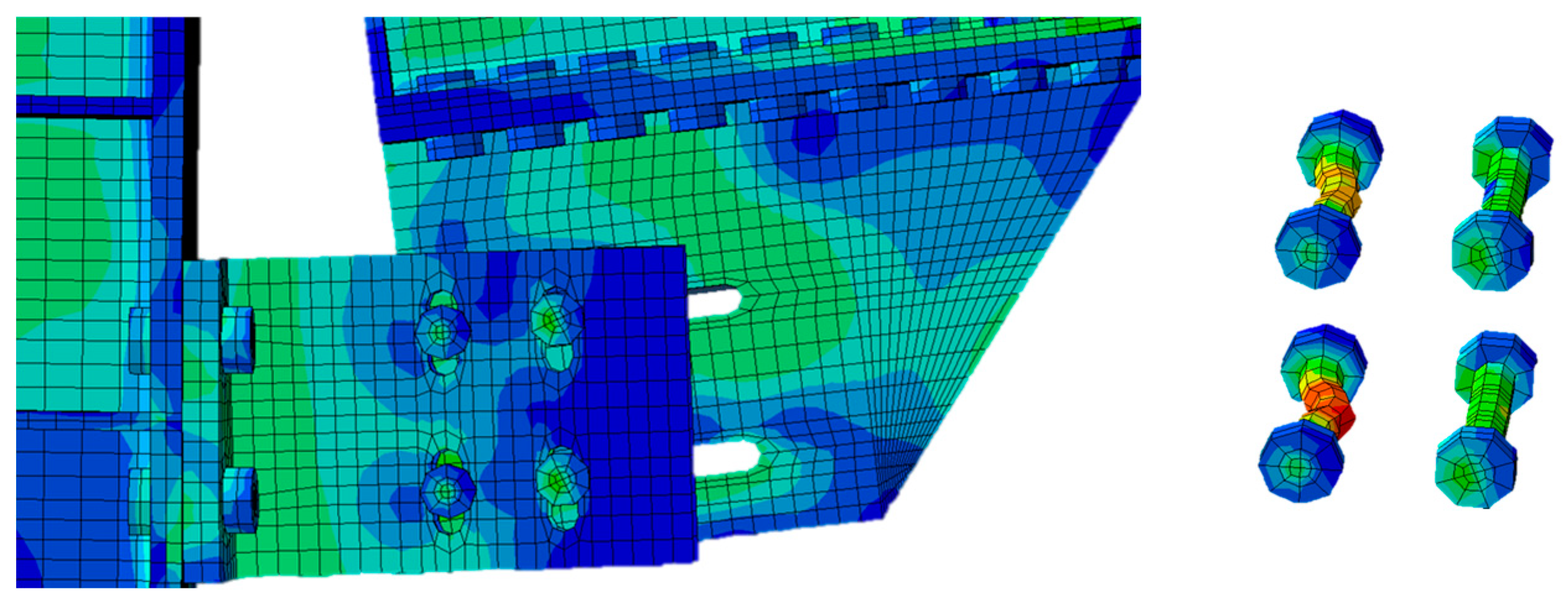
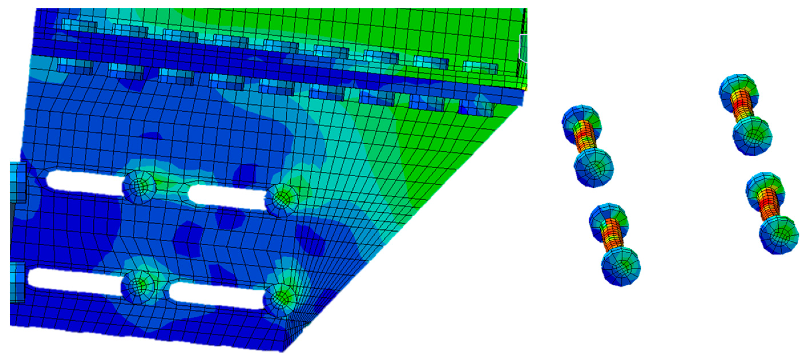
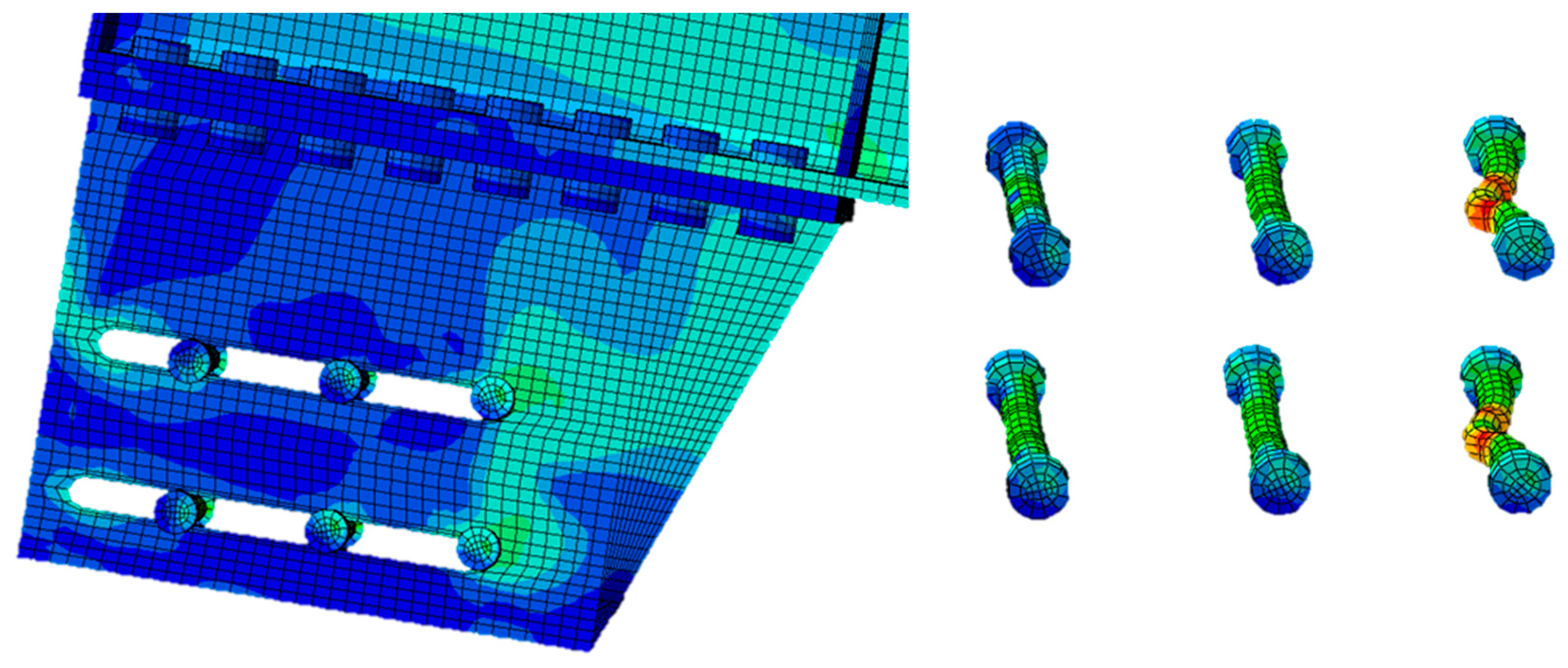
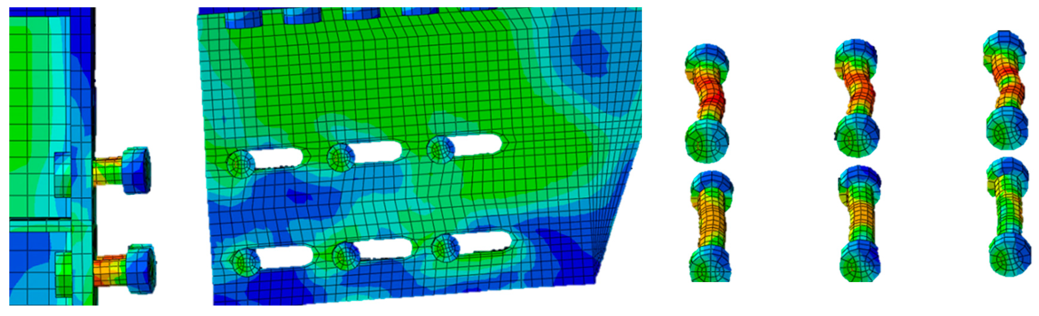
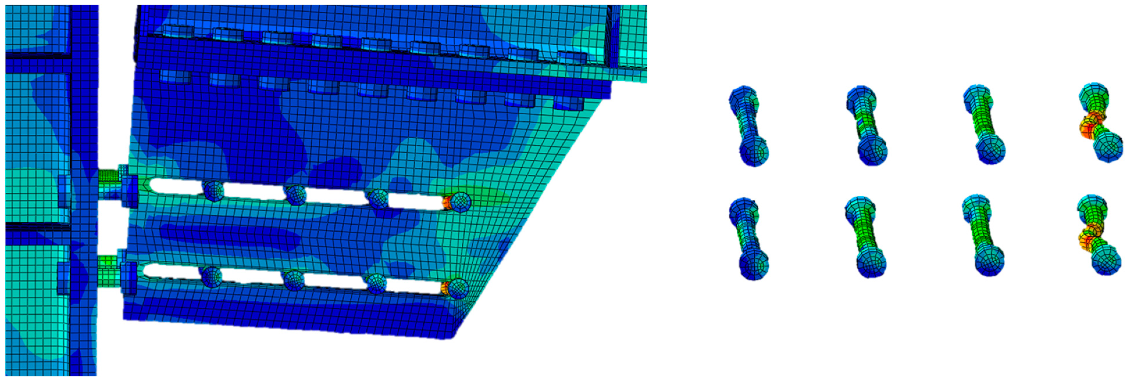
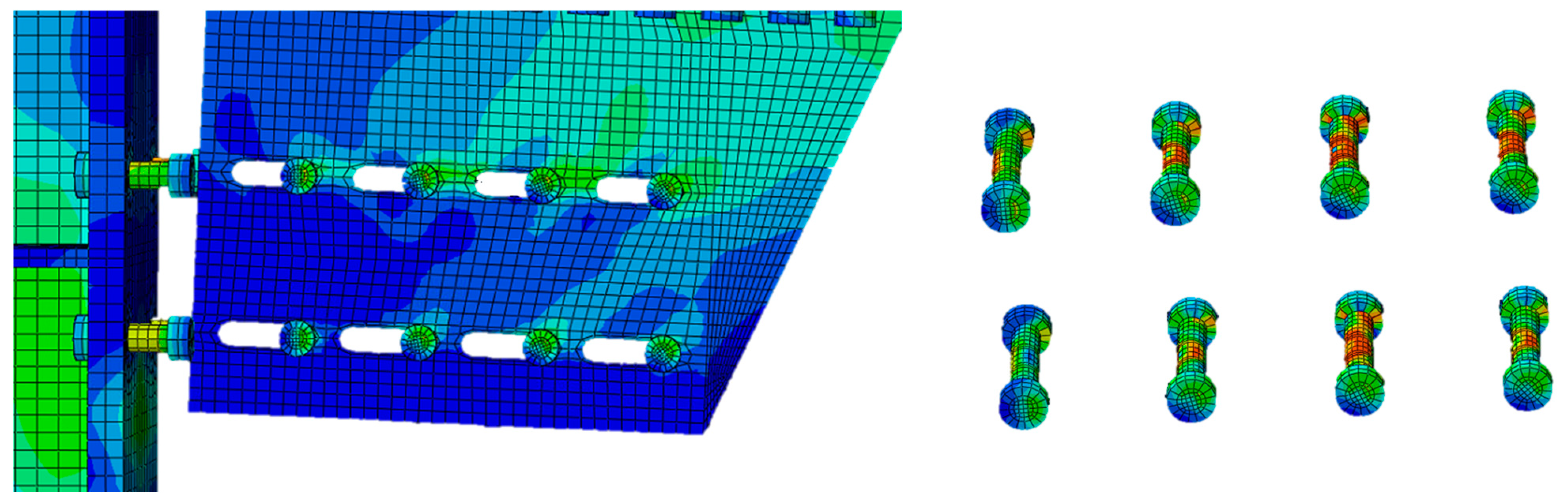
4. Results and Discussion
5. Conclusions
- The behavior of moment-rotation curves in both hogging and sagging conditions follows four distinct phases, indicating the critical phases of joint performance.
- Consistent stiffness was observed in the first elastic phase across different assemblies, with the D2B assembly showing slightly higher stiffness, highlighting the importance of the assembly configuration.
- Joints with multiple-slot dampers exhibited increased stiffness in the second elastic phase due to the engagement of a larger number of bolts, underscoring the effectiveness of the damper design.
- The calibration of hole sizes, tailored to the damper’s geometry and positioning, is crucial for optimizing performance, emphasizing the need for precise design considerations.
- Based on the insights gained from this research, the primary recommendation is to carefully size the slots according to the detailed explanations provided in Section 2 with reference to Equation (3).
- Future experimental testing, particularly focusing on multiple-slot configurations, is advocated to validate these findings and further refine damper designs for enhanced seismic resilience of steel structures.
Author Contributions
Funding
Institutional Review Board Statement
Informed Consent Statement
Data Availability Statement
Conflicts of Interest
Nomenclature
| Number of bolts in the damper | |
| Bolt diameter | |
| Lever arm of the connection | |
| Bending utilization factor | |
| Plastic moment of the beam | |
| Friction resistance | |
| Design bolt preload | |
| Number of friction surfaces | |
| Characteristic static friction coefficient | |
| Safety factor for the loss of initial preload | |
| Lcolumn | Length of the column |
| Lbeam | Length of the beam |
| Superior base of the haunch | |
| Inferior base of the haunch | |
| Height of the haunch | |
| Base of the haunch flange | |
| Thickness of the haunch flange | |
| Thickness of the web flange | |
| Base of the T-stub | |
| Height of the T-stub flange | |
| Thickness of the T-stub flange | |
| Length of the T-stub | |
| Thickness of the T-stub web | |
| Base of the L-stub | |
| Height of the L-stub flange | |
| Thickness of the L-stub flange | |
| Length of the L-stub | |
| Thickness of the L-stub web | |
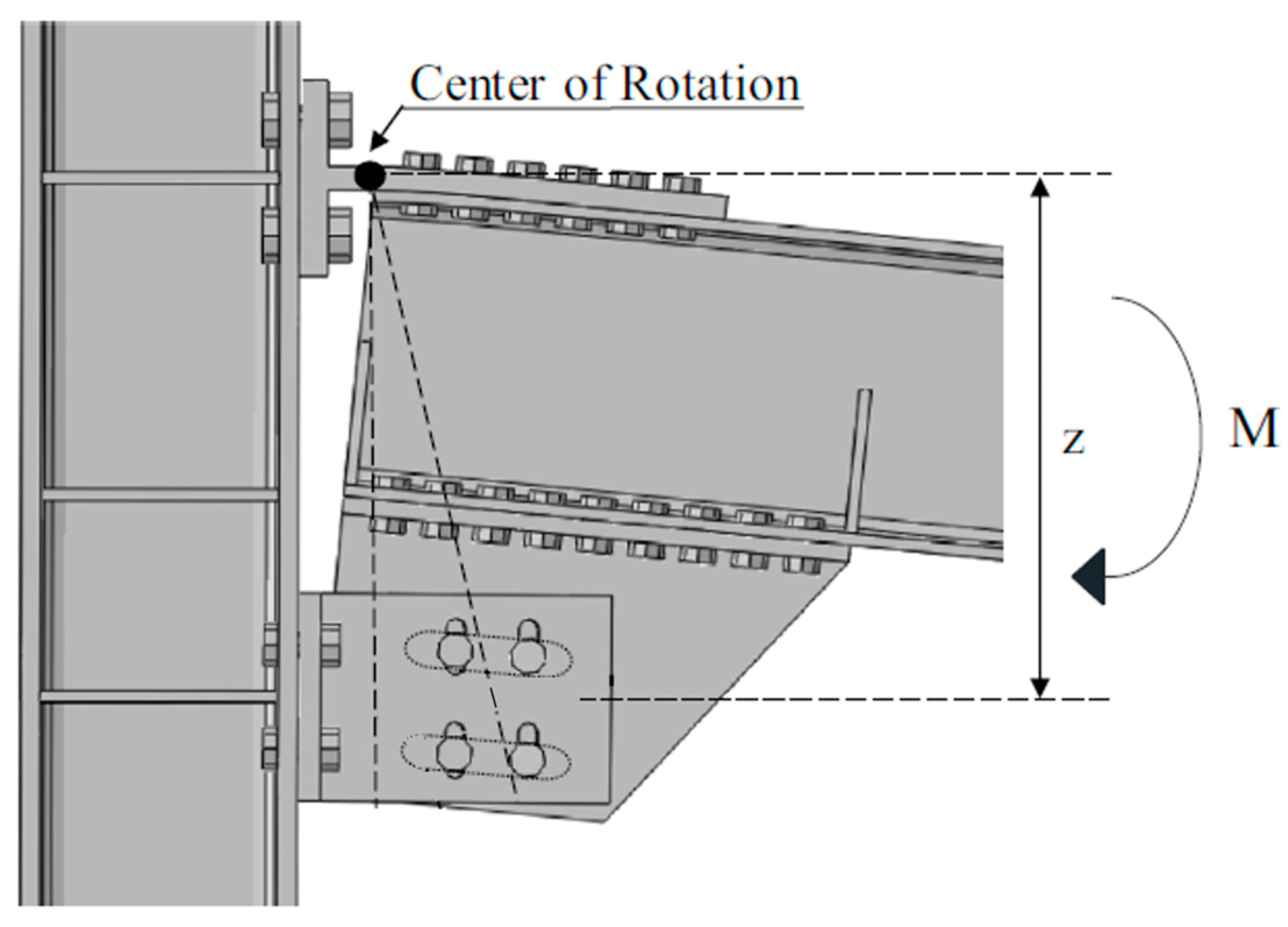
| Distance between the center of rotation and the bolts centroid | |
| Design rotation | |
| Bolt hole clearance | |
| Half-lengths of the slots | |
| Slope of the first elastic branch | |
| Slope of the second elastic branch | |
| Maximum normalized bending moment (1st branch) | |
| Maximum normalized bending moment (2nd branch) | |
| Normalized bending moment at the design rotation |
References
- Montuori, R.; Nastri, E.; Piluso, V. Theory of plastic mechanism control: A new approach for the optimization of seismic resistant steel frames. Earthq. Eng. Struct. Dyn. 2022, 51, 3598–3619. [Google Scholar] [CrossRef]
- Montuori, R.; Nastri, E.; Todisco, P. Influence of the seismic shear proportioning factor on steel MRFs seismic performances. Soil Dyn. Earthq. Eng. 2021, 141, 106498. [Google Scholar] [CrossRef]
- Piluso, V.; Pisapia, A.; Castaldo, P.; Nastri, E. Probabilistic Theory of Plastic Mechanism Control for Steel Moment Resisting Frames. Struct. Saf. 2019, 76, 95–107. [Google Scholar] [CrossRef]
- Dell’Aglio, G.; Montuori, R.; Nastri, E.; Piluso, V. A critical review of plastic design approaches for failure mode control of steel moment resisting frames. Ing. Sismica 2017, 34, 82–102. [Google Scholar]
- Grigorian, C.E.; Yang, T.S.; Popov, E.P. Slotted bolted connection energy dissipators. Earthq. Spectra 1993, 9, 491–504. [Google Scholar] [CrossRef]
- Soong, T.T.; Spencer, B.F. Supplemental energy dissipation: State-of-the-art and state of-the-practice. Eng. Struct. 2002, 24, 243–259. [Google Scholar] [CrossRef]
- Tartaglia, R.; D’Aniello, M.; Campiche, A.; Latour, M. Symmetric friction dampers in beam-to-column joints for low-damage steel MRFs. J. Constr. Steel Res. 2021, 184, 106791. [Google Scholar] [CrossRef]
- Ferrante Cavallaro, G.; Francavilla, A.B.; Latour, M.; Piluso, V.; Rizzano, G. Cyclic response of low yielding connections using different friction materials. Soil Dyn. Earthq. Eng. 2018, 114, 404–423. [Google Scholar] [CrossRef]
- MacKinven, H. Sliding Hinge Joint for Steel Moment Frames Experimental Testing; ENCI 493 Project Report; Department of Civil Engineering, University of Canterbury: Canterbury, UK, 2006. [Google Scholar]
- MacRae, G.A.; MacKinven, H.; Clifton, G.C.; Pampanin, S.; Walpole, W.; Butterworth, J. Tests of sliding hinge joints for steel moment frames. In Proceedings of the 8th Pacific Structural Steel Conference—Steel Structures in Natural Hazards, PSSC 2007, Wairakei, New Zealand, 13–16 March 2007; Volume 2, pp. 109–114. [Google Scholar]
- Butterworth, J.; Clifton, C.; MacRae, G. Developments in steel frame joints in New Zealand. Struct. Eng. 2008, 86, 20–21. [Google Scholar]
- Khoo, H.H.; Clifton, C.; Butterworth, J.; MacRae, G.; Ferguson, G. Influence of steel shim hardness on the sliding hinge joint performance. J. Construct. Steel Res. 2012, 72, 119–129. [Google Scholar] [CrossRef]
- MacRae, G.A.; Clifton, G.C.; Mackinven, H.; Mago, N.; Butterworth, J.; Pampanin, S. The sliding hinge joint moment connection. Bull. N. Z. Soc. Earthq. Eng. 2010, 43, 202–212. [Google Scholar] [CrossRef]
- Ramhormozian, S.; Clifton, G.C.; MacRae, G.A. The Asymmetric Friction Connection with Belleville Springs in the Sliding Hinge Joint. In Proceedings of the 2014 New Zealand Society for Earthquake Engineering (NZSEE) Annual Technical Conference, Auckland, Australia, 21–23 March 2014. [Google Scholar]
- Ramhormozian, S.; Clifton, G.C.; Nguyen, H.; Cowle, K. Determination of the Required Part-Turn of the Nut with Respect to the Number of Free Threads under the Loaded Face of the Nut in Fully Tensioned High Strength Friction Grip Property Class 8.8 Bolts. In Proceedings of the Steel Innovations Conference, Auckland, New Zealand, 3–4 September 2015. [Google Scholar]
- CEN EN 1993:1-8; Design of Steel Structures—Part 1–8: Design of Joints. European Committee for Standardization: Brussels, Belgium, 2005.
- Di Lauro, F.; Montuori, R.; Nastri, E.; Piluso, V. Partial safety factors and overstrength coefficient evaluation for the design of connections equipped with friction dampers. Eng. Struct. 2019, 178, 645–655. [Google Scholar] [CrossRef]
- Piluso, V.; Rizzano, G.; Latour, M.; Francavilla, A.; Di Benedetto, S.; Landolfo, R.; D’Aniello, M.; da Silva, L.S.; Santiago, A.; Santos, A.; et al. Informative Documents of the Dissemination Project FREEDAM-PLUS. GA 899321-2020. Available online: https://www.steelconstruct.com/eu-projects/freedam-2/documents/ (accessed on 1 May 2021).
- Nastri, E.; D’Aniello, M.; Zimbru, M.; Streppone, S.; Landolfo, R.; Montuori, R.; Piluso, V. Seismic response of steel moment resisting frames equipped with friction beam-to-column joints. Soil Dyn. Earthq. Eng. 2019, 119, 144–157. [Google Scholar] [CrossRef]
- CEN EN 1993-1-3; Eurocode 3—Design of Steel Structures—Part 1–1: General Rules and Rules for Buildings. European Committee for Standardization: Brussels, Belgium, 2005.
- Dassault. Abaqus 6.17—Abaqus Analysis User’s Manual; Dassault Systèmes Simulia Corp.: Johnston, RI, USA, 2017. [Google Scholar]
- Latour, M.; D’Aniello, M.; Zimbru, M.; Rizzano, G.; Piluso, V.; Landolfo, R. Removable friction dampers for low-damage steel beam-to-column joints. Soil Dyn. Earthq. Eng. 2018, 115, 66–81. [Google Scholar] [CrossRef]
- D’Aniello, M.; Cassiano, D.; Landolfo, R. Monotonic and cyclic inelastic tensile response of European preloadable GR10.9 bolt assemblies. J. Constr. Steel Res. 2016, 124, 77–90. [Google Scholar] [CrossRef]
- D’Aniello, M.; Cassiano, D.; Landolfo, R. Simplified criteria for finite element modeling of European preloadable bolts. Steel Comp Struct 2017, 24, 643–658. [Google Scholar]


| Damper | Beam Section | Column Section | |||||
|---|---|---|---|---|---|---|---|
| [-] | [mm] | [mm] | Minimum | Maximum | Minimum | Maximum | |
| D1 | 4 | 16 | 170 | IPE 270 | IPE 450 | HE 240 B | HE 240 B |
| D2 | 4 | 20 | 250 | IPE 360 | IPE 600 | HE 240 B | HE 320 M |
| D3 | 6 | 20 | 250 | IPE 400 | IPE 600 | HE 300 B | HE 320 M |
| D4 | 8 | 20 | 250 | IPE 500 | IPE 750 × 196+ | HE 280 M | HE 650 M |
| D5 | 8 | 24 | 330 | IPE 600 | IPE 750 × 196+ | HE 320 M | HE 650 M |
| Beam Size | ) [-] | |||
|---|---|---|---|---|
| IPE 270 | - | - | D1 | D1 |
| IPE 300 | - | D1 | D1 | D1 |
| IPE 360 | D1 | D1 | D2 | D2 |
| IPE 400 | D1 | D2 | D2 | D2 |
| IPE 450 | D1 | D2 | D2 | D3 |
| IPE 500 | D2 | D2 | D3 | D3 |
| IPE 550 | D2 | D3 | D3 | D4 |
| IPE 600 | D2 | D3 | D4 | D4 |
| IPE 750 × 147 | D3 | D4 | D5 | D5 |
| IPE 750 × 161 | D3 | D4 | D5 | D5 |
| IPE 750 × 173 | D3 | D4 | D5 | D5 |
| IPE 750 × 196+ | D4 | D5 | D5 | D5 |
| Assembly | Beam | Column | Bolts (10.9 class) | ||||
|---|---|---|---|---|---|---|---|
| [mm] | [mm] | [-] | |||||
| D1A | IPE 270 | HE 240 B | 3000 | 3500 | 0.47 | M16 | 4 |
| D2B | IPE 450 | HE 360 B | 3000 | 3500 | 0.47 | M20 | 6 |
| D2C | IPE 600 | HE 320 M | 3000 | 3500 | 0.35 | M20 | 8 |
| D3B | IPE 550 | HE 500 M | 3000 | 3500 | 0.47 | M20 | 8 |
| Assembly | Haunch | T-stub | L-stub | |||||||||||||
|---|---|---|---|---|---|---|---|---|---|---|---|---|---|---|---|---|
| [mm] | [mm] | [mm] | [mm] | [mm] | [mm] | [mm] | [mm] | [mm] | [mm] | [mm] | [mm] | [mm] | [mm] | [mm] | [mm] | |
| D1A | 440 | 251 | 245 | 135 | 15 | 15 | 205 | 170 | 25 | 345 | 20 | 75 | 180 | 20 | 296 | 20 |
| D2B | 555 | 424 | 340 | 180 | 20 | 20 | 270 | 190 | 30 | 405 | 25 | 90 | 220 | 30 | 399 | 30 |
| D2C | 720 | 504 | 392 | 195 | 30 | 25 | 270 | 210 | 40 | 480 | 30 | 90 | 286 | 35 | 569 | 35 |
| D3B | 795 | 582 | 492 | 195 | 30 | 25 | 290 | 250 | 40 | 555 | 30 | 90 | 364 | 45 | 637 | 35 |
| Assembly | Half-Lengths of the Slots | |||
|---|---|---|---|---|
| Upper [mm] | Lower [mm] | [mm] | [mm] | |
| D1A | 31.3 | 38.4 | 405 | 495 |
| D2B | 26.6 | 31.0 | 658 | 768 |
| D2C | 33.5 | 38.8 | 960 | 1090 |
| D3B | 32.9 | 40.2 | 828 | 960 |
| Haunch (Direction) | ||||||
|---|---|---|---|---|---|---|
| [rad−1] | [rad−1] | [-] | [-] | [-] | ||
| D1A | Single (up) | 50.62 | 23.92 | 0.48 | 1.17 | 0.62 |
| Multiple (up) | 51.10 | 35.75 | 0.48 | 1.22 | 0.61 | |
| Single (down) | 54.77 | 21.38 | 0.54 | 1.11 | 0.48 | |
| Multiple (down) | 55.30 | 36.93 | 0.48 | 1.16 | 0.48 | |
| D2B | Single (up) | 63.50 | 35.22 | 0.47 | 1.14 | 0.51 |
| Multiple (up) | 61.07 | 41.82 | 0.48 | 1.31 | 0.53 | |
| Single (down) | 51.60 | 38.92 | 0.48 | 1.17 | 0.68 | |
| Multiple (down) | 94.73 | 39.95 | 0.47 | 1.33 | 0.54 | |
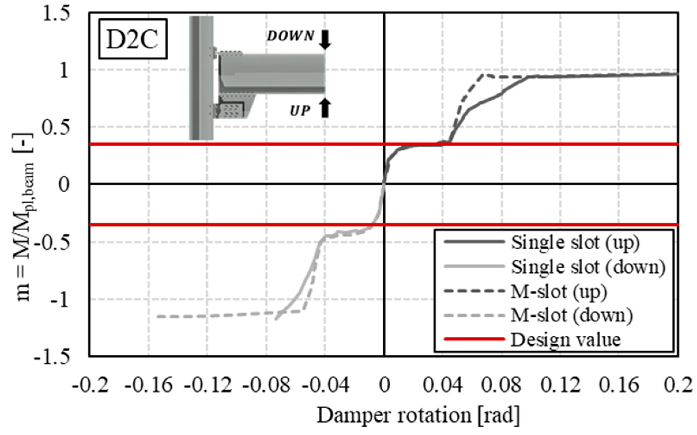
| D2C | Single (up) | 66.86 | 23.11 | 0.38 | 0.94 | 0.38 |
| Multiple (up) | 57.15 | 40.95 | 0.37 | 0.97 | 0.37 | |
| Single (down) | 74.09 | 29.73 | 0.40 | 1.10 | 0.46 | |
| Multiple (down) | 64.70 | 45.76 | 0.40 | 1.17 | 0.47 | |
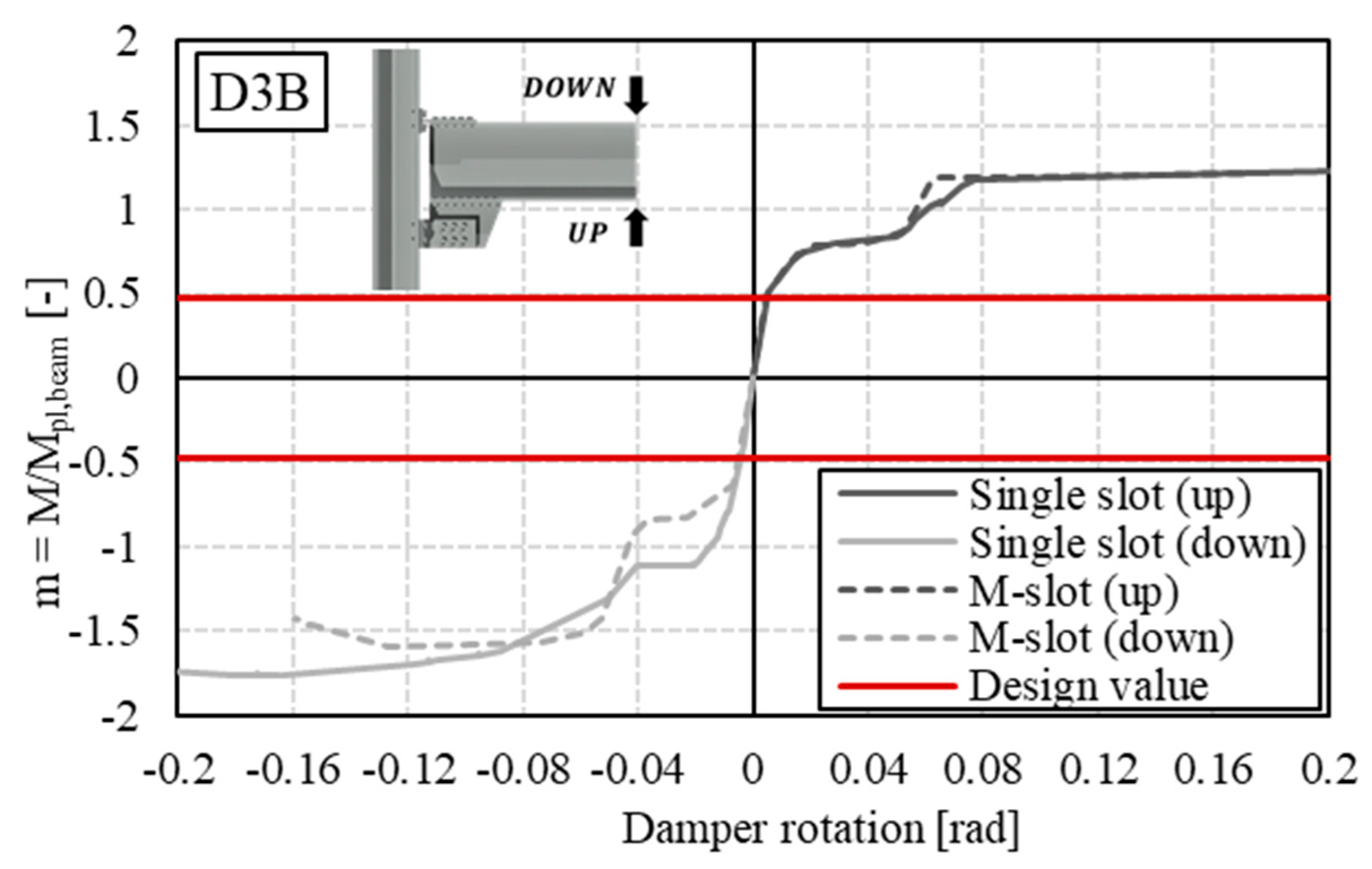
| D3B | Single (up) | 100.76 | 17.82 | 0.49 | 0.78 | 0.80 |
| Multiple (up) | 113.29 | 28.98 | 0.48 | 0.77 | 0.79 | |
| Single (down) | 126.88 | 20.87 | 0.63 | 1.59 | 1.10 | |
| Multiple (down) | 95.03 | 35.43 | 0.64 | 1.51 | 0.89 |
Disclaimer/Publisher’s Note: The statements, opinions and data contained in all publications are solely those of the individual author(s) and contributor(s) and not of MDPI and/or the editor(s). MDPI and/or the editor(s) disclaim responsibility for any injury to people or property resulting from any ideas, methods, instructions or products referred to in the content. |
© 2024 by the authors. Licensee MDPI, Basel, Switzerland. This article is an open access article distributed under the terms and conditions of the Creative Commons Attribution (CC BY) license (https://creativecommons.org/licenses/by/4.0/).
Share and Cite
D’Aniello, M.; Montuori, R.; Nastri, E.; Piluso, V.; Todisco, P. Parametric Finite Element Study on FREEDAM Beam to Column Joints with Different Details of the Haunch Slotted Holes. Appl. Sci. 2024, 14, 2770. https://doi.org/10.3390/app14072770
D’Aniello M, Montuori R, Nastri E, Piluso V, Todisco P. Parametric Finite Element Study on FREEDAM Beam to Column Joints with Different Details of the Haunch Slotted Holes. Applied Sciences. 2024; 14(7):2770. https://doi.org/10.3390/app14072770
Chicago/Turabian StyleD’Aniello, Mario, Rosario Montuori, Elide Nastri, Vincenzo Piluso, and Paolo Todisco. 2024. "Parametric Finite Element Study on FREEDAM Beam to Column Joints with Different Details of the Haunch Slotted Holes" Applied Sciences 14, no. 7: 2770. https://doi.org/10.3390/app14072770