Dual-View Three-Dimensional Display Based on Direct-Projection Integral Imaging with Convex Mirror Arrays

1
HoloDigilog Human Media Research Center, Nano Device Application Center, Kwangwoon University, 21, Gwangun-ro, Nowon-Gu, Seoul 01890, Korea
2
HoloDigilog Human Media Research Center, Kwangwoon University, 21, Gwangun-ro, Nowon-Gu, Seoul 01890, Korea
3
Intelligent Medical Platform Research Center, Kyunghee University, 1732, Deogyeong-daero, Giheung-gu, Yongin-si, Gyeonggi-do 17104, Korea
4
HoloDigilog Human Media Research Center, 3D Display Research Center, Kwangwoon University, 21, Gwangun-ro, Nowon-Gu, Seoul 01890, Korea
*
Author to whom correspondence should be addressed.
Appl. Sci. 2019, 9(8), 1577; https://doi.org/10.3390/app9081577
Submission received: 27 March 2019
/
Revised: 10 April 2019
/
Accepted: 11 April 2019
/
Published: 16 April 2019
(This article belongs to the Special Issue Holography, 3D Imaging and 3D Display)
Abstract
:Dual three-dimensional (3-D) view displays have been attracting much attention in many practical application fields since they can provide two kinds of realistic 3-D images with different perspectives to the viewer. Thus, in this paper, a new type of the dual-view 3-D display system based on direct-projection integral imaging using a convex-mirror-array (CMA) is proposed. Two elemental image arrays (EIAs) captured from each of the two 3-D objects are synthesized into a single dual-view EIA (DV-EIA) with a selective sub-image mapping scheme. The divergent beam of the projector containing the information of the DV-EIA is projected onto the CMA. On each convex mirror of the CMA, left and right-view components of the DV-EIA are separated and reflected back into their viewing directions. Two different 3-D scene images are then integrated and displayed on their respective viewing zones. Ray-optical analysis with the parallel-ray-approximation method and experiments with the test 3-D objects on the implemented 22″ DV 3-D display prototype confirm the feasibility of the proposed system in the practical application
1. Introduction
Thus far, many kinds of dual-view (DV) displays have been developed due to the high interest in various application fields including car navigation, multi-vision, medicine and digital signage [1,2,3,4,5,6,7,8,9]. For example, a DV car navigation system presents live traffic information to the driver while showing movies to the passenger [4,5,6]. Moreover, the DV digital signage system can provide two kinds of advertising videos to each of the two groups of customers standing on the street at different viewing directions [3]. In this way, the need for supplying respective displays for each of the driver and passenger, and each group of the customers can be removed, which then results in saving associated cost and reduction space occupied by the other displays [4,5,6]. Of course, each individual in the car and each customer group on the street can enjoy the same video contents simultaneously in their positions.
In fact, there exists a very close similarity between the DV and stereoscopic displays in terms of generating two different views. That is, the DV display provides two different views to the two observers located at different viewing directions, while the stereoscopic display delivers two perspectives of an input 3-D scene with a binocular disparity to each of the left and right eyes of an observer [9]. This functional similarity implies that the operational principle of the DV display might be closely related to that of the stereoscopic display. Thus, just like the conventional stereoscopic displays employing the polarizing glasses or shutter glasses, as well as the lenticular sheets or parallax barriers for their generation of two or multi-views, DV displays also use the related optical elements for generation of their two different views [10,11,12].
Thus, DV displays can be largely classified into spatial and time-multiplexed systems [13,14,15,16,17,18,19]. In the spatial-multiplexed system, the main pixel of the DV LCD (liquid crystal device) panel consists of a right sub-pixel (RSP) and a left sub-pixel (LSP), and those two different sub-pixels project two different images to the viewers at different directions. Spatial-multiplexed DV LCD displays have been successfully demonstrated with parallax barriers and lenticular sheets [16]. However, in these systems, additional optical elements must be attached to their LCD panels, the absolute spatial-resolution of the displayed images must be reduced in half, and crosstalk may occur between two displayed images [16]. On the other hand, in the time-multiplexed system, two different images are time-sequentially provided to two viewers with the absolute full spatial-resolution of the LCD panel [18]. For this, this system requires a directional backlight module with complex reflectors, and an LCD panel with faster response time. In addition, it may suffer from crosstalk and flicker-noise problems [18].
Meanwhile, since the 3-D display can provide a realistic 3-D image with different perspectives to the viewer, some research on the DV 3-D display was recently carried out [19]. In most conventional DV 3-D display systems, time or spatial-multiplexed stereoscopic images are used for providing two different stereoscopic images to the two different viewers. However, those systems require four times of spatial and time-multiplexing processes, compared to the 2-D display system. It may result in a one-quarter reduction of the spatial resolution in the spatial-multiplexed system and four-fold acceleration of the LCD response time in the time-multiplexed system, respectively [19]. These practical problems prevent the stereoscopic technique from being widely applied for the DV 3-D display.
As an alternative, an integral imaging-based DV 3-D display was proposed [20,21,22,23]. Wu and et al. suggested a DV 3-D LCD system based on the lens array-based off-axis integral imaging method [19]. However, since the narrow viewing-zone of the ordinary lens array-based integral imaging system was shared by two viewing-zones, sufficient viewing-areas for the DV 3-D display could not be offered. Thus, they tried to employ a polarization parallax barrier to improve the viewing angle [21], but it suffered from the degraded resolution and brightness of the displayed 3-D images due to the polarization barriers blocking light coming from the elemental image array (EIA).
In fact, for the practical application of the 3-D DV display, two viewing-zones must be completely separated and have relatively large viewing-angles to experience the perspective changes of 3-D images. For this, J. Jeong et al. proposed a projection-type DV 3-D display based on integral imaging [23]. They used a series of optical elements, such as a collimator, a lenticular lens with a vertical diffuser, and convex lens array for generation of a collimated beam, separation of DV images with enhanced viewing-angles, and integration of 3-D images to be displayed in their viewing zones, respectively. These additional optical elements, however, may degrade the quality of the reconstructed 3-D images. Moreover, there exists an overlapped viewing-zone between the left and right 3-D images with some distortion due to the crossing of the left and right rays. The scale of this system may also depend on the practical sizes of the lenticular lens and collimator. Furthermore, this convex-lens-array-based projection integral imaging (CLA-PII) system shows a narrower viewing angle than the of the convex-mirror-array-based system [23].
To alleviate those problems, in this paper, we propose a practical type of a scalable DV 3-D display system based on convex-mirror-array-based direct projection integral imaging (CMA-DPII). The proposed system is simply composed of a projector and a CMA, where two kinds of EIAs for each of the two different input 3-D scenes are generated with the on-axis pickup integral imaging system and synthesized into a single EIA, which is called DV-EIA, based on the selective sub-image mapping (SSIM) method. Here, the DV-EIA contains all information of the intensities, perspectives, viewing zones of those two different input 3-D scenes. The divergent beam of the projector containing the information of the DV-EIA is directly projected onto the surface of the CMA without any additional optical elements. On every convex mirror, each of the left and right-scene components of the DV-EIs are instantaneously separated and reflected back into their viewing directions. Two different 3-D scene images are then integrated and displayed in their viewing zones with their viewing angles.
In fact, the viewing angle of the proposed CMA-DPII system would be much more enhanced than that of the conventional CLA-PII system since each convex mirror can be made to have a much smaller f-number than the corresponding convex lens [24]. Moreover, contrary to the conventional system, each of the two viewing-zones and angles of the proposed system can be made changeable with the SSIM process, as well as a scalable DV 3-D display without flip-image and Moiré disturbance problems can be implemented [25]. To confirm the feasibility of the proposed system, ray-optical analysis with the parallel-ray-approximation (PRA) method, as well as optical experiments with test 3-D objects on the implemented 22′′ DV 3-D display prototype is performed, and the results are compared with those of the conventional system.
2. Methods
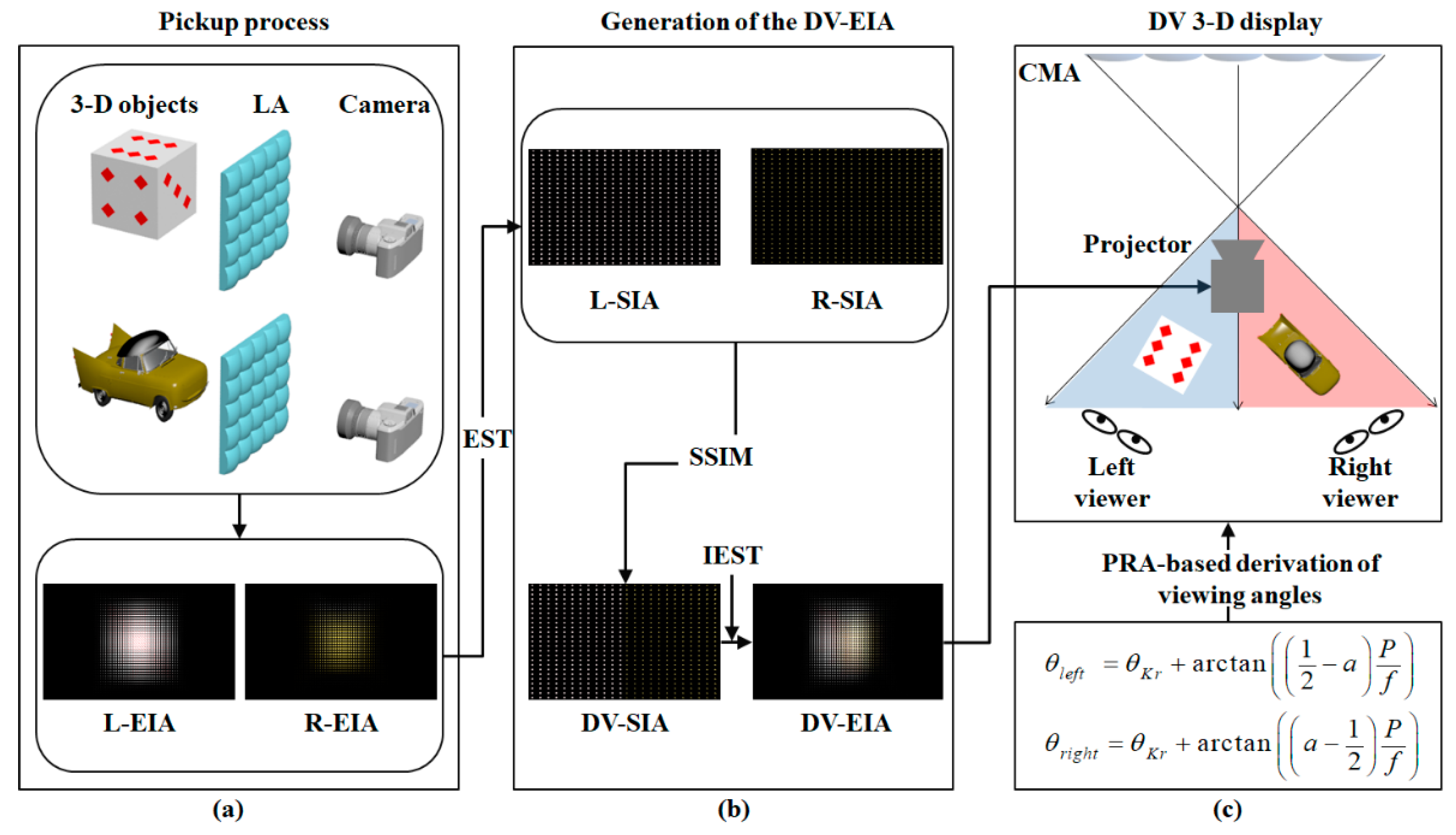
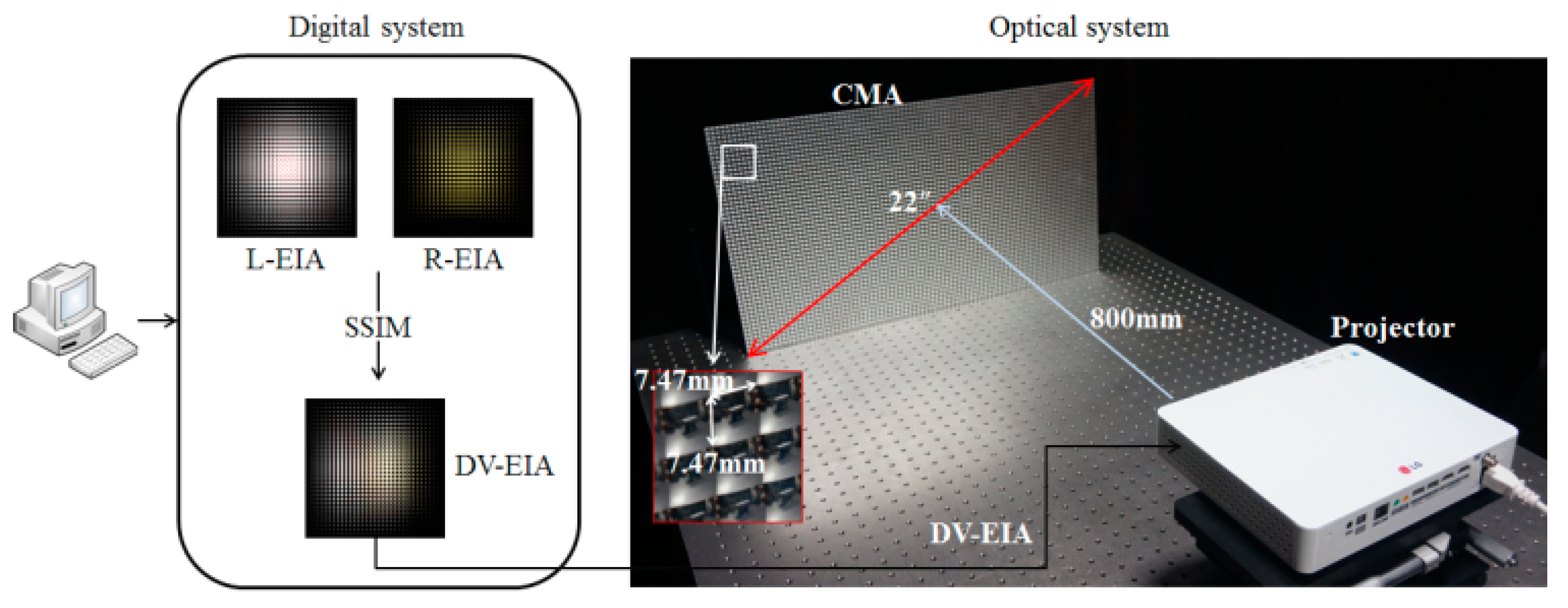
Figure 1 shows an overall block diagram of the proposed system, which is composed of three-step processes. At the 1st step, two kinds of EIAs for each of the two different 3-D objects were generated based on the on-axis pickup integral imaging system, which are called left-EIA (L-EIA) and right-EIA (R-EIA) corresponding to each of the left and right views, respectively. In the 2nd step, these two EIAs of the L-EIA and R-EIA were multiplexed into a single EIA, which is called DV-EIA, based on the selective sub-image mapping (SSIM) method. At the 3rd step, the divergent beam of the projector containing the information of the DV-EIA was projected onto the CMA. Then, on each convex mirror of the CMA, the left and right-view components of the DV-EIA were instantaneously separated and reflected back into their viewing directions with their viewing angles. Finally, two different 3-D scenes were integrated and displayed in their viewing zones.
2.1. Capturing of Two Kinds of EIAs Based on on-Axis Integral Imaging
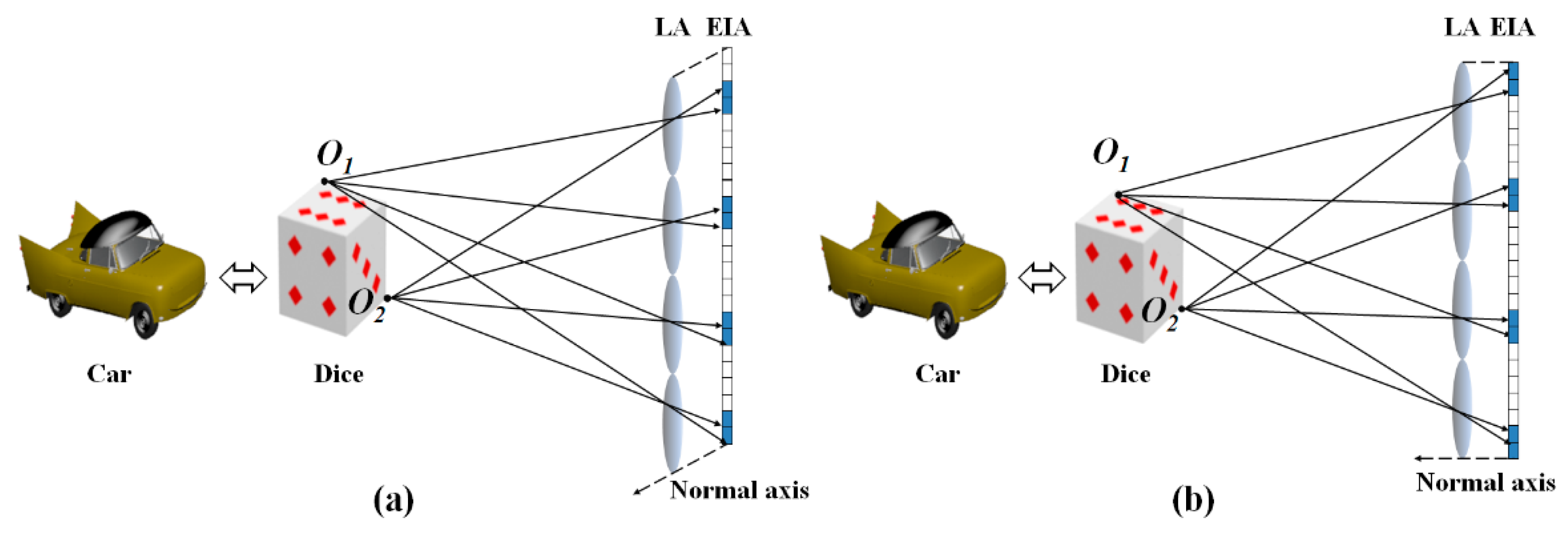
Figure 2 shows two types of optical configurations for pickup and display of the EIA of a 3-D object in integral imaging, such as the on-axis and off-axis integral imaging systems. In the off-axis integral imaging system of Figure 2a, the normal axis of the EI surface and optical axis of the elemental lens were made to be offset. In other words, the optical axis of the pickup lens array was somewhat shifted from the normal axis of the EIA plane [23]. As seen in Figure 2, rays coming from the object points of O1 and O2, could be picked up on the different locations of the EIA depending on the relative position of the elemental lens. These two picked-up EIAs were then synthesized into a single DV-EIA. For the reconstruction of the DV-EIA, the same type of the off-axis integral imaging system was used. This off-axis integral imaging system has been used in the conventional LCD panel-type and projection-type integral imaging DV 3-D systems [20,21,22,23].
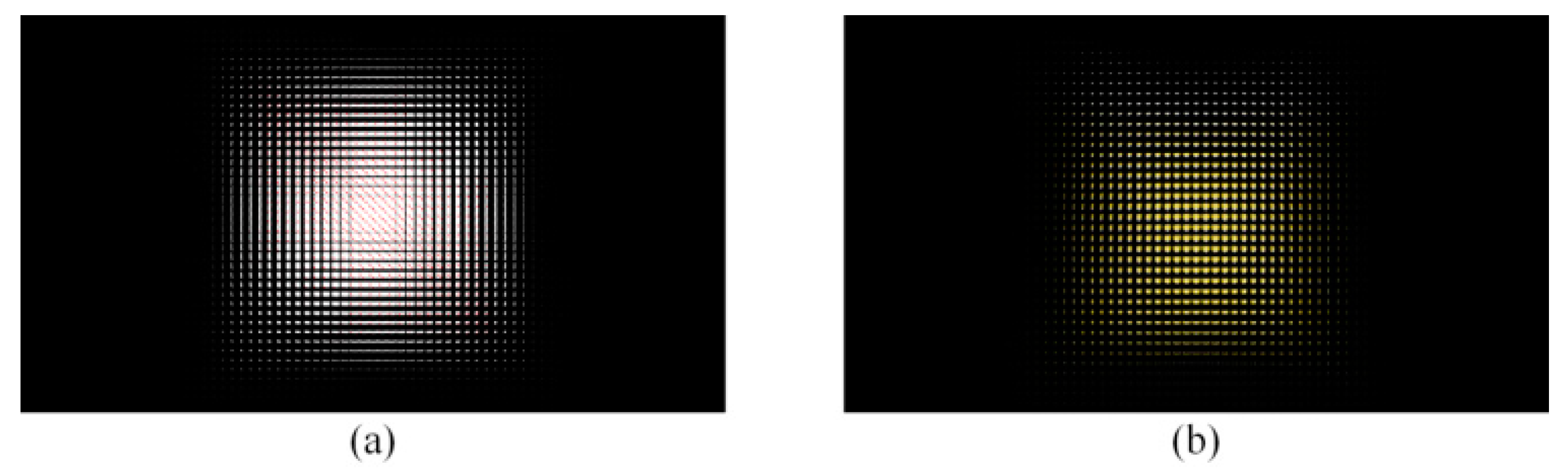
On the other hand, Figure 2b shows the on-axis integral imaging system, which looks like the ordinary integral imaging system. As seen in Figure 2b, the normal axis of the EI surface and optical axis of the elemental lens were on the same axis. The same on-axis integral imaging system was also used in the display process just like the ordinary integral imaging system. Unlike the conventional CLA-PII system, the proposed CMA-DPII system was implemented on the ordinary on-axis integral imaging system. For instance, Figure 3 shows two kinds of EIAs captured for each of the two different 3-D objects of ‘Dice’ and ‘Car’ based on the on-axis integral imaging system of Figure 2b.
2.2. Synthesis of Two EIAs into a Single DV-EIA
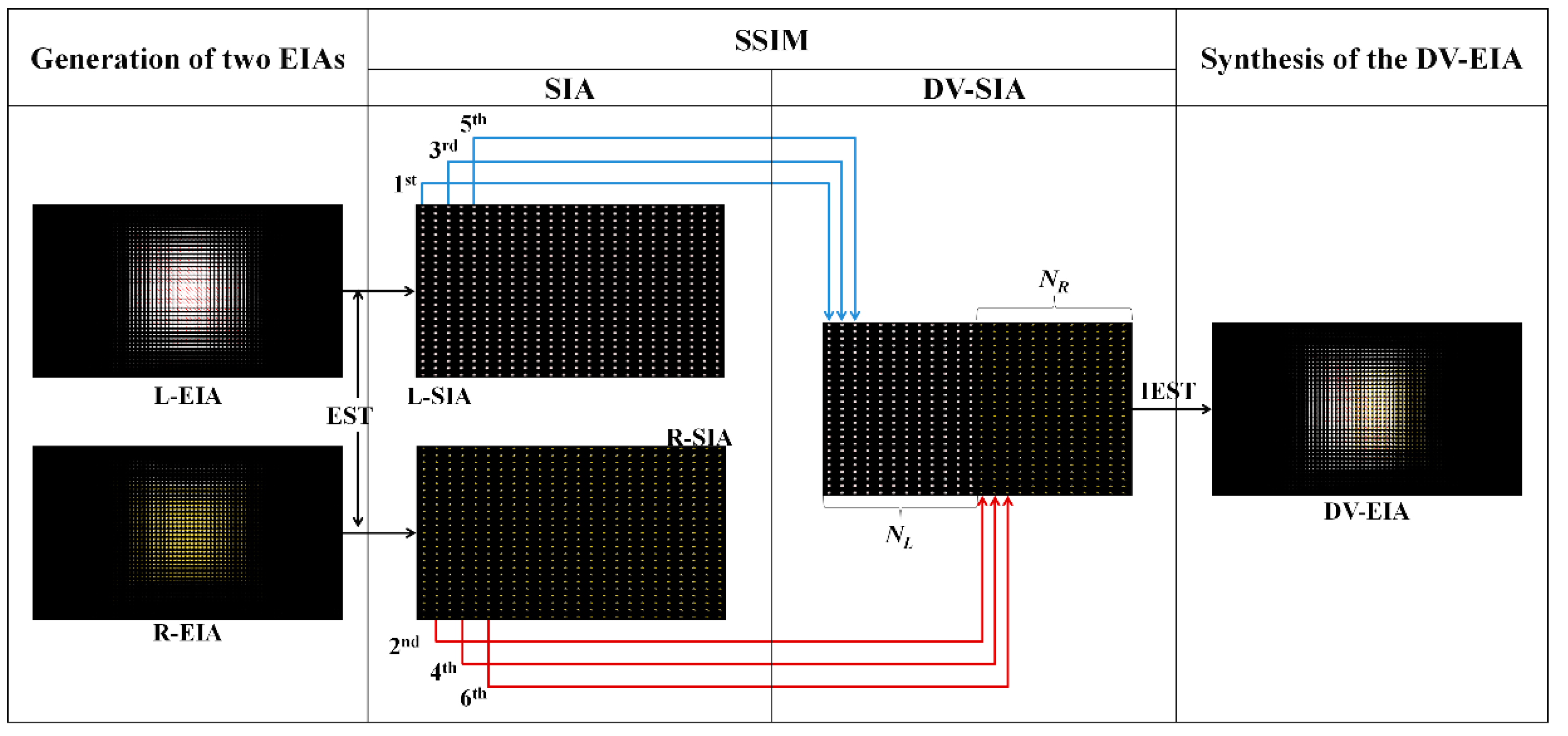
To generate the DV zones corresponding to each of the left and right views, two EIAs captured from each of the two different 3-D objects were multiplexed into a single EIA, which is called DV-EIA, based on the SSIM method, as mentioned above. Figure 4 shows a conceptual diagram of the SSIM method, which is composed of a four-step process.
At the 1st step, two EIA were captured from each of the two different 3-D objects, which were assigned to the L-EIA and R-EIA, respectively. At the second step, L-EIA and R-EIA were transformed into the corresponding sub-image arrays (SIAs), which are called L-SIA and R-SIA, respectively, based on the EIA-to-SIA transformation (EST) method [26]. At the 3rd step, odd and even number of components of the EIs were selectively chosen from each of the L-SIA and R-EIA and mapped into their corresponding left-half and right-half parts of the dual-view sub-image array (DV-SIA), respectively.
Here, NL and NR, respectively, represent the total number of SIs selected from the L-SIA and R-SIA, and allocated to their corresponding left and right-half parts of the DV-EIA. NDV (=NL + NR) also denotes the total number of SIs mapped into the DV-SIA along the horizontal direction, where the number of pixels in each EI was equal to the number of SIs. This DV-SIA was then transformed into its corresponding DV-EIA using the inverse-EST (IEST) method. At the 4th step, the DV-EIAs for the two L-EIA and R-EIA were finally generated and used for separate displaying of two different 3-D objects into their viewing zones. Meanwhile, in the conventional system, the left and right viewing zones are set to be equal and physically fixed by the employed optical elements, such as the lens array and lenticular lens array, whereas in the proposed system, a parameter of α can be employed for controlling the relative sizes of the left and right viewing zones, where α is defined as a relative portion of the NL in NDV and expressed by Equation (1).
According to the relationship between the EIA and SIA, NDV and NL become equal to the total number of pixels of the DV-EI and number of pixels of the L-EI allocated to the left-hand side of the DV-EI, respectively. Thus, NL turn out to be α × NDV and the other portion of the NDV, NR becomes (1 − α) × NDV, which represents the number of pixels of the R-EI allocated to the right-hand side of the DV-EI. This scalability of the left and right viewing zones is another property of the proposed system in the practical application.
2.3. Direct Projection of the DV-EIA onto the CMA for the DV 3-D Display
Figure 5 shows an optical configuration of the direct-projection integral imaging system for the DV 3-D display of the synthesized DV-EIA with the CMA, where straight lines denote the real rays in the real space, whereas dashed lines represent the virtual rays generated by the reflected beams on the surface of the CMA. In Figure 5, the beam projector, where the synthesized DV-EIA was loaded, was located far from the CMA, enabling the performance analysis of the proposed system using parallel-ray-approximation (PRA) under the far-field condition, which is to be discussed in the next section. In the conventional projection DV 3-D display system, however, this far field condition may not be considered since the diverging beam coming from the beam projector is set to be parallelized by using a collimator. Here, in the proposed system, the divergent beam of the projector containing the information of the DV-EIA was projected onto the CMA. This diverging beam carrying the DV-EIA was reflected on the surface of the CMA and divided into the left and right EIAs (L-EIA and R-EIA) on each component of the CMA in the real space. From each of the L-EIA and R-EIA, the left and right viewing zones were generated in the space. Further, each of the L-EIA and R-EIA was integrated into each viewing zone, and two different 3-D objects were reconstructed in their viewing zones.
2.3.1. Parallel-Ray Approximation Method
In the field of the array antenna, the parallel-ray approximation (PRA) method has been used in computing the frequency response of the array antenna rather than the ray-tracing method [27,28,29,30]. Here, the array antenna is built with a 2-D periodic array structure. Since this array antenna looks very similar to the convex mirror array (CMA), the PRA method can be applied for the performance analysis of the proposed CMA-DPII system under the far-field condition.
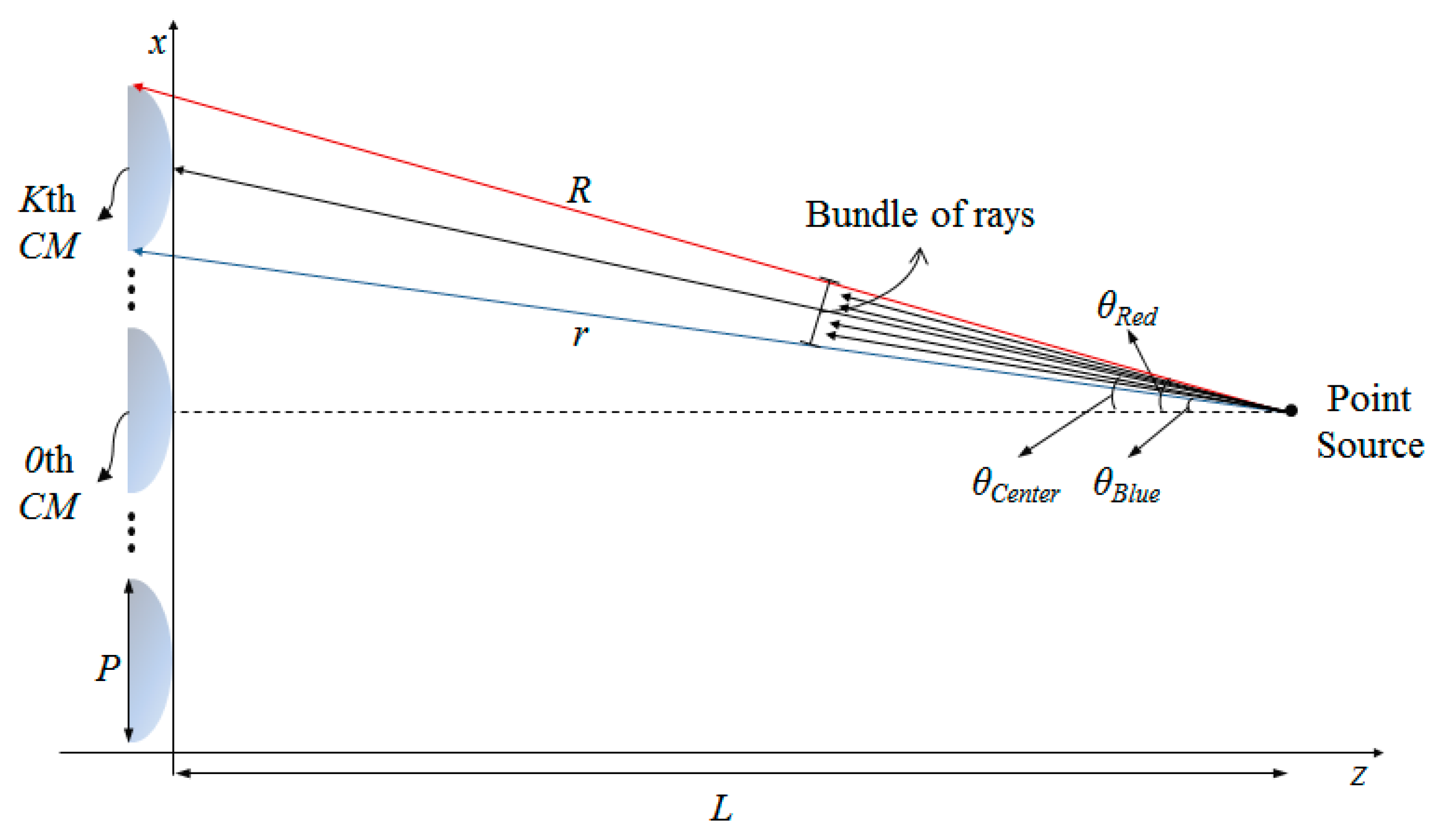
Thus, in this paper, the PRA method was employed for the ray-optical analysis of the proposed system. Figure 6 shows an optical geometry for analyzing the proposed system based on the PRA method. In Figure 6, P and K represent the pitch of an elemental convex mirror and the maximum number of convex mirrors along the x-direction. The center of the 0th convex mirror was set to be the origin of the vertical x-coordinate and a point source whose vertical coordinate was the same as that of the 0th convex mirror. L denotes the distance between the point source and CMA. Here, two red and blue-color rays coming from the point source were assumed to arrive at the upper and bottom edges of the Kth convex mirror, respectively, where R and θRed denote the optical path length of the red-color ray and its incidence angle to the Kth convex mirror, while r and θBlue denote the optical path length of the blue-color ray and its incidence angle to the Kth convex mirror, respectively. In addition, θCenter represents the angle of the ray incoming to the center of the Kth convex mirror.
The proposed CMA-DPII-based DV 3-D display system can be made under the far-field condition, which enables the use of the PRA method for the analysis of its operational performance. Under the far-field condition of P/L < 0.01, the optical path lengths of the red and blue-color rays from the point source to the Kth convex mirror, R and r, as well as the incidence angles of the red and blue-color ray to the Kth convex mirror, θRed and θBlue, can be approximated to be equal. With this relationship of θRed ≈ θBlue, red and blue-color rays can be assumed to be parallel rays with the same propagation angles to the Kth convex mirror. Thus, the propagation angles of all those rays in a bundle can be given by θCenter ≈ θRed ≈ θBlue, where θCenter represents the incidence angle of the center ray. In other words, the incidence angles of rays to the Kth convex mirror can be modeled as a single representative angle of θCenter, which is given by Equation (2).
Equation (2) means that the incidence angle of the center ray to each convex mirror depends on the vertical location of the convex mirror (KP) and the distance between the point source and the CMA plane (L). Since the CMA consists of a number of same-sized convex mirrors with regular intervals along the x and y-directions, each bundle of rays incoming to each convex mirror has different incidence angles. According to Equation (2), as the number of convex mirrors of K increases, its corresponding incidence angle of θCenter can be increased up to 90°. Now, when a point source is replaced with a beam projector, all rays coming from the projector carrying the DV-EIA can be approximated to be a set of bundles of parallel rays with corresponding DV-EIs, and the operational performance of the proposed system, which is simply composed of a beam projector and a CMA, can be analyzed based on the PRA method.
2.3.2. Analysis of the Dual-Viewing Zones and Angles
Thus, under this circumstance, dual-viewing zones and angles of the proposed system can be analyzed. If these parallel rays containing the information data of the DV-EIA, are projected into the surfaces of each convex mirror, left and right-view components of the DV-EIs are separated and reflected back into their viewing directions with their viewing angles. Then, two different 3-D object images are integrated from all those surfaces of the CMA and displayed in their viewing zones.
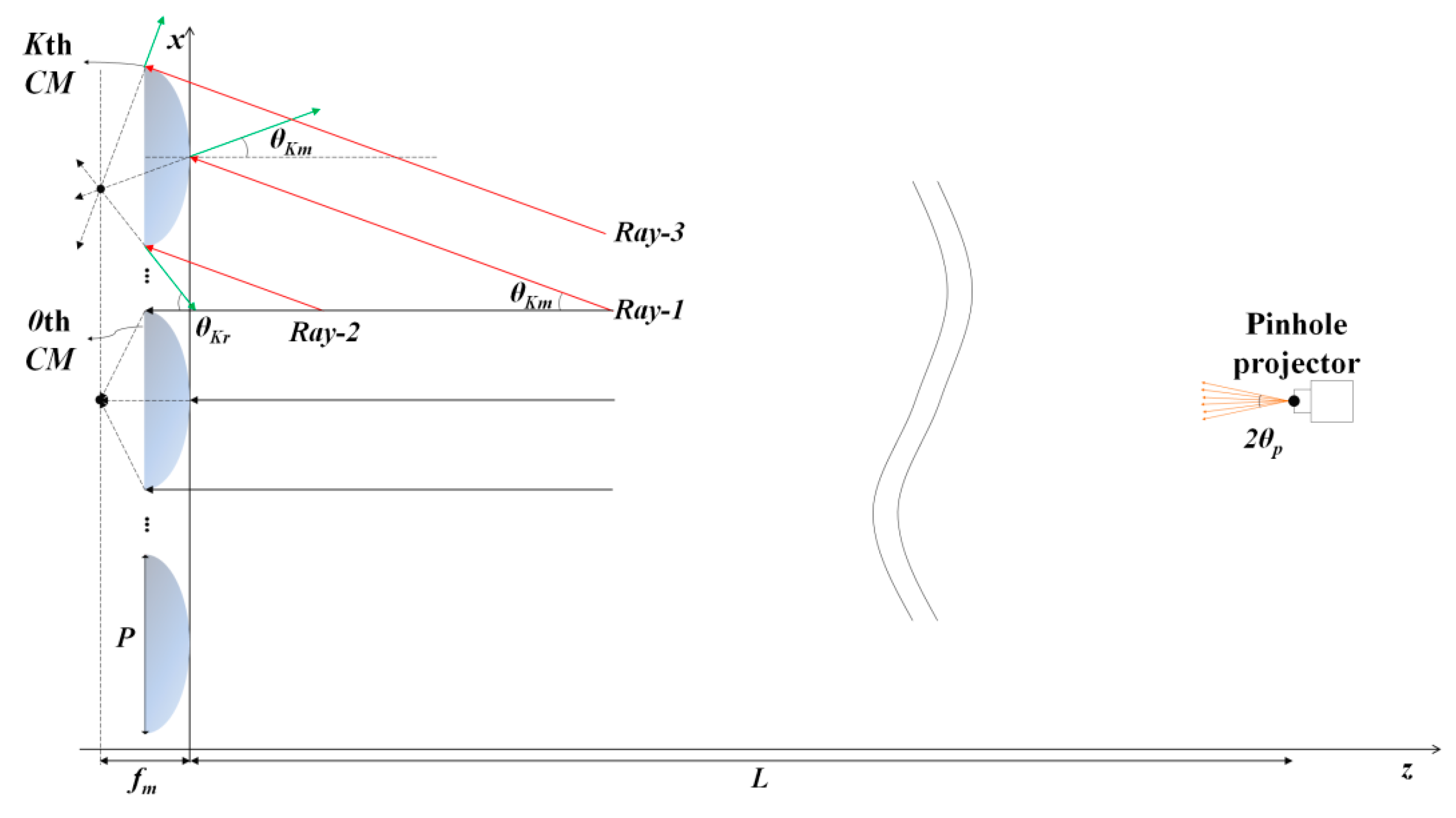
Figure 7 shows an optical configuration of the bundle of parallel rays coming from the projector and incident to the Kth convex mirror based on the ray-tracing model. As seen in Figure 7, a bundle of red-color parallel rays with information of one component of the DV-EIA, is assumed to be incident onto the Kth convex mirror. Green-color rays represent the reflected beams on the surface of the Kth convex-mirror for their corresponding incident rays, forming rays through the backward extension of the reflected ones. Here, fm denotes a focal length of the convex mirror, and θp represents the half beam angle of the projector being located far away from the CMA plane.
The Ray-1, representing the center ray of the bundle of rays incident to the Kth convex mirror with the incidence angle of θKm, is reflected back from the surface of the Kth convex mirror to make the reflected ray with the reflection angle of θKm. This reflection of the incident ray is equivalent to its virtual propagation into the convex mirror as seen in Figure 7. The Ray-2 and Ray-3 also represent the parallel rays incident to both edges of the Kth convex mirror. Just like the Ray-1 case, Ray-2 and Ray-3 are also reflected back from the convex mirror to make their reflected rays, which are equivalent to their virtually propagated rays into the convex lens. All those virtually propagated rays into the convex lens come across on the same points called a focal point of the convex lens as seen In Figure 7.
Based on the ray-tracing model, all virtually propagated rays for each convex mirror are focused on its focal point at the focal plane of the CMA as seen in Figure 7. Since the angle of a bundle of parallel rays incident to the Kth convex mirror is related to the relative position of the convex mirror (KP) and the distance from the projector to the CMA (L) under the far-field condition, the incidence angle of the center ray to the Kth convex mirror, θKm can be calculated based on ray-optics, and given by Equation (3).
Even though the incidence angle to the corresponding convex mirror can be increased as the number of K increases, its maximum angle value may be practically bounded by the diverging angle of the projector, 2θp. The whole bunch of rays between the Ray-2 and Ray-3 incident to the Kth convex mirror corresponds to one DV-EI of the DV-EIA. This DV-EI is composed of a pair of L-EI and R-EI. Each of the left and right viewing zones can be generated by the reflected propagations of the L-EI at the Kth convex mirror and R-EI at the Kth convex mirror, respectively. Thus, the virtual propagation angle of the Ray-2 needs to be calculated for calculating the viewing zones of the proposed system because the reflection angle of the Ray-2 affects the viewing angle for each viewing zone. Here, the reflection angle θKr of the Ray-2 on the Kth convex mirror can be derived as Equation (4).
Equation (4) shows that the reflection angle, θKr depends on the incidence angle, θKm. In particular, in case the incidence angle of the ray becomes less than or equal to the value of arctan(1/(2f#)), the focal point exists within the mirror pitch of P. Otherwise, the focal point may be placed beyond the mirror pitch of P, which means that dual-viewing zones cannot be properly generated in this case. Thus, the maximum value of one-half of the diverging beam angle of the projector must be less than or equal to arctan(1/(2f#)). Here, it is noted that the viewing zone is defined as the movable range in the viewing space where the viewer can see a full-resolution image [31].
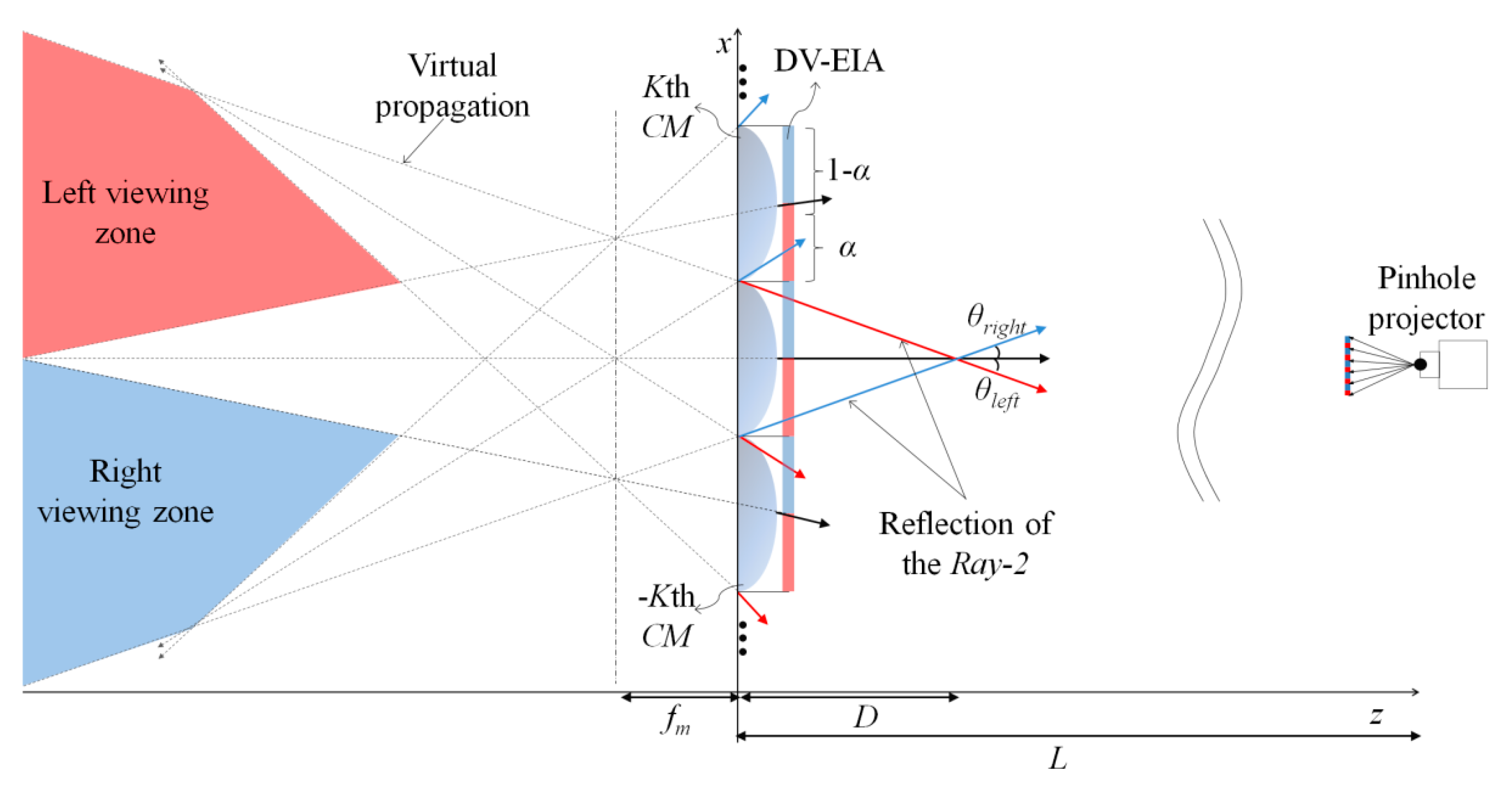
Figure 8 shows an optical configuration for analyzing the dual-viewing zones of the proposed system generated from the DV-EIA and CMA under the far-field condition. As mentioned above, the DV-EIA is generated by a combined use of the L-EIA and R-EIA with the parameter of α. As seen in Figure 8, the red and blue areas represent the ray zones reflected from the L-EI and R-EI, respectively. In addition, black rays represent the boundary rays of the left and right viewing zones. When the total number of convex mirrors is set to be 2K + 1, each of the left and right viewing angles can be decided by the Kth and − Kth CM, respectively.
The left viewing zone can be generated by overlapping of all L-EIs of the DV-EIA and its boundary can be decided by the virtual propagation of the Ray-2 on the Kth convex mirror and boundary ray on the 0th convex mirror, whereas the right viewing zone is generated by overlapping of all R-EIs of the DV-EIA and its boundary is decided by the virtual propagation of the Ray-2 on the − Kth convex mirror and boundary ray on the 0th convex mirror. Thus, the left and right viewing angles of θleft and θright can be given by Equation (5).
As seen in Equation (5), viewing angles depend on the value of α. That is, as the value of α increases, the relative portion of the L-EI in the DV-EI increases, which results in an increase of the corresponding left viewing angle. Whereas when the value of α decreases, the right viewing angle gets extended. For the case of α = 0.5, the left and right viewing angles become exactly the same, which corresponds to the conventional display system. In Figure 8, D represents the distance from the CMA for the left and right viewing zones to be separated along the z-direction in the real space, which can be derived by Equation (6).
As seen in Equation (6), the separation distance of D mostly depends on the pitch of the convex mirror (K) and the reflection angle of the Ray-2 on the Kth convex mirror (θKr). Thus, viewers standing beyond the separation distance in the real space can see each of those reconstructed 3-D objects on the two different directions.
2.4. Reconstruction of Dual 3-D Views with their Viewing Angles
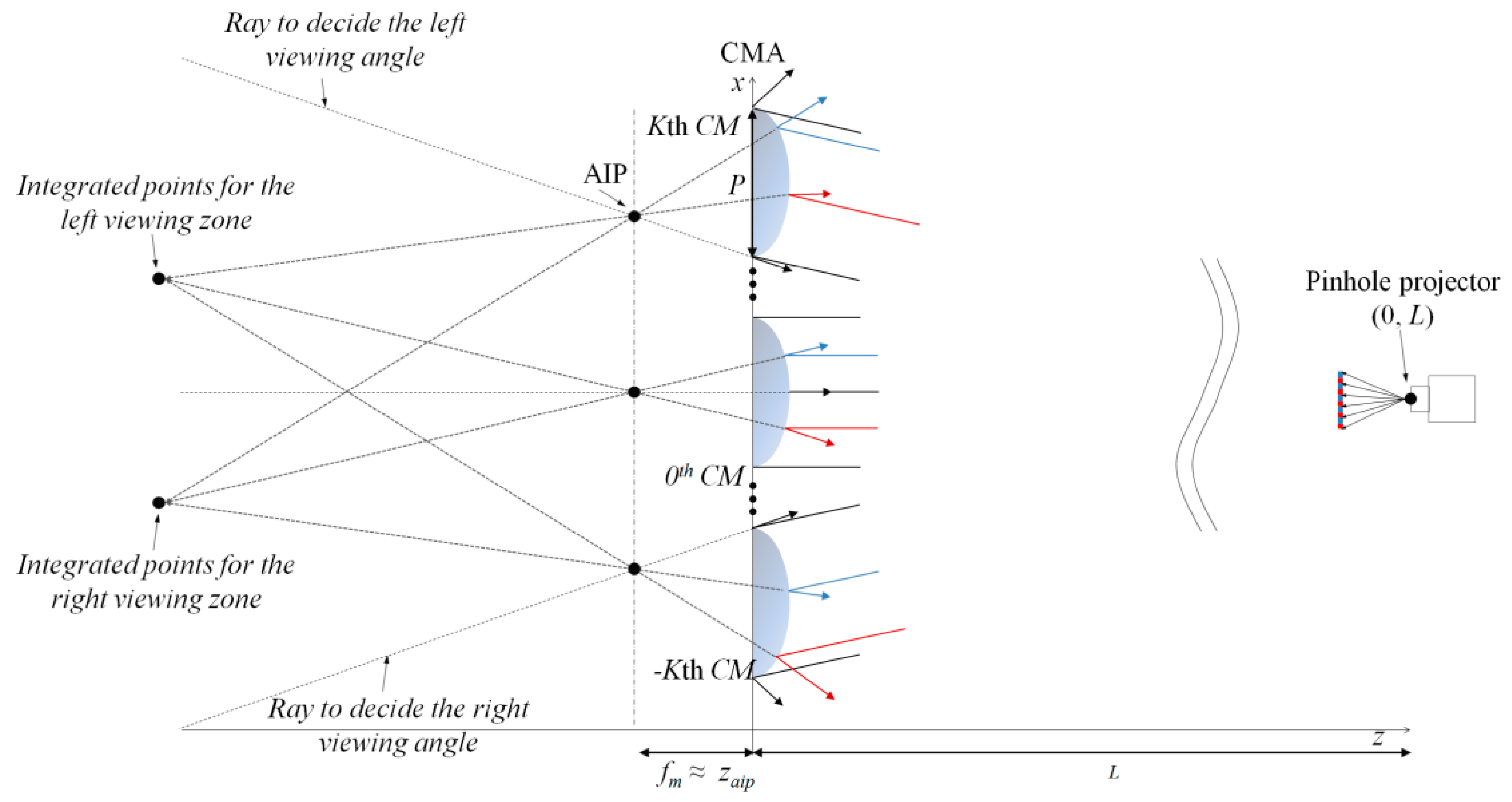
Figure 9 shows the optical configuration of the reconstructed dual 3-D views in their viewing zones. The aperture of a pinhole projector is positioned at the distance of L from the CMA along the z-direction. Aperture image point (AIP) is generated by the pinhole of the projector acting as a point light source [32]. Here, zaip represents the position of the AIP along the z-direction and the total number of convex mirrors is set to be (2K + 1), which are located along the x-direction.
The divergent beam of the projector containing the information of the DV-EIA is projected onto the CMA. Since the distance of L is much larger than the pitch of the convex mirror, each ray incoming to the corresponding convex mirror is assumed to be parallel rays with the same incidence angles under the far-field condition. Incoming rays with the L-EI and R-EI are reflected on the corresponding convex mirror and generate a single AIP depending on the convex mirror because a single pinhole projector is used in the display system. Here, the position of the AIP zaip becomes fm because incoming rays are approximated to be the parallel rays based on the PRA method. The number of AIPs is the same as the total number of convex mirrors. All those AIPs generated in each CM are integrated in the left and right viewing zones, which are decided by the rays incoming from the bottom of the Kth convex mirror and from the top of the Kth convex mirror. Thus, different 3-D senses in the left and right viewing zones can be reconstructed from these integrated AIPs.
3. Results
3.1. Experimental Setup
Figure 10 shows an experimental setup of the proposed system, which is simply composed of a pair of the CMA and beam projector. As a projector, the LG beam projector (Model: LG PF85K) whose resolution, brightness and size were 1920 × 1080 pixels, 1000 ANSI-lumens and 275 × 219 × 45 mm, respectively, was used. The total diverging angle (2θp) and depth-of-field (DoF) of this projector were estimated to be 39°, and ranged from 62 cm to 372 cm, respectively. In addition, for the experiments, a 22′′CMA whose pitch and curvature radius were 7.47 mm and 15.50 mm, respectively, was fabricated and located at the distance of 800 mm from the beam projector. Here, the focal length of an elemental CM of the CMA was calculated to be 7.32 mm.
As mentioned above, to test the feasibility of the proposed system in the practical application, a 22′′CMA was specially designed and fabricated. That is, the CMA was manufactured by coating the aluminum particles being spread from the thermal evaporator on the surface of a base convex lens array to make a high-reflector aluminum layer. Here, aluminum was used as a coating material because the reflectance for the visible light becomes much more than 90%. Thus, the convex lens array with a thin aluminum layer acted as a convex mirror array. Each convex mirror had the same curvature and pitch as the base convex lens, but its focal length became much shorter than that of the base convex lens. In the experiment, pitches and focal lengths of the base convex lens and convex mirror were 7.47 mm, 29.88 mm, and 7.47 mm, 7.32 mm, respectively. That is, the focal length of the convex mirror became 4.08-fold shorter than that of the corresponding convex lens. In fact, as the focal length of the convex mirror got shorter, its f-number (f#) also decreased, which then resulted in an increase of the viewing angle of the corresponding CMA by a factor of 2 × arctan(1/2(f#)) [24]. Table 1 shows the detailed specification of the pickup and display setups.
3.2. Capturing of the L-EIA and R-EIA from Each of the Two Test 3-D Objects
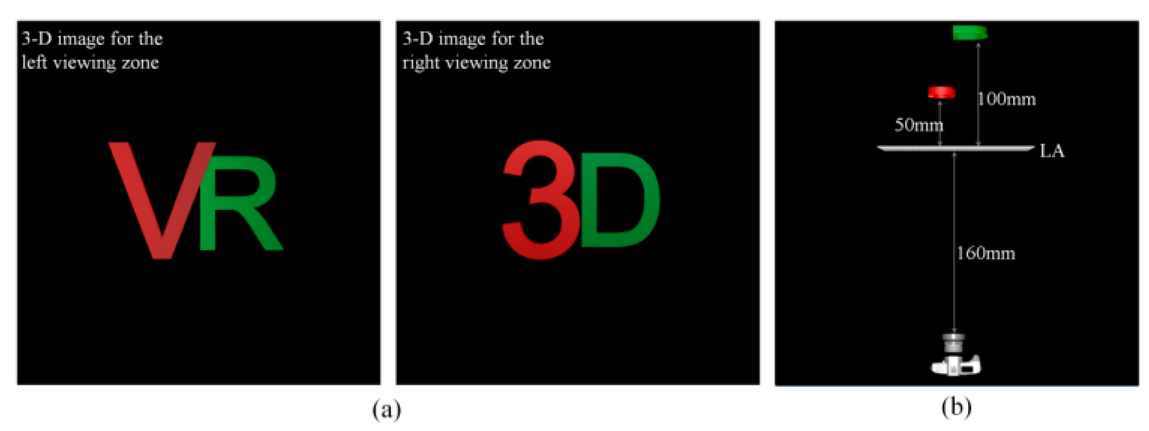
As the test objects, two kinds of 3-D objects were computationally generated with the 3D Max, which were composed of two pairs of 2-D images with different depths. As seen in Figure 11a, one of them was the 3-D object composed of two English alphabetical letters of ‘V’ and ‘R’, which were located at the depth planes of 50mm and 100mm, respectively, and the other one was the 3-D object composed of a numeric letter of ‘3’ and an English alphabetical letter of ‘D’, which were also located at the same depth planes of 50 mm and 100 mm, respectively, from the pickup lens array.
Here, ‘V’ and ‘3’ images were colored with red, whereas ‘R’ and ‘D’ images were colored with green for the visual separation. In addition, two 3-D objects of ‘VR’ and ‘3D’ were assigned to each of the left and right views for the DV 3-D display, respectively.
These two test 3-D objects were computationally picked up with the on-axis integral imaging system of Figure 11b. As mentioned above, two English alphabetical and numeric images of ‘V’ and ‘3’ were located at the distances of 50 mm, while two other English alphabetical images of ‘R’ and ‘D’ were located at the distances of 100 mm from the pick-up lens array, where depth differences between them are given by 50 mm. Here, the pickup camera was set to be located at the distance of 160 mm from the lens array. In the pickup process, the number of lenses of the lens array and the pitch of the lens array and focal length of an elemental lens are in the Table 1, respectively.
Figure 12 shows two kinds of EIAs captured from two 3-D objects of ‘VR’ and ‘3D’, which were designated to the L-EIA and R-EIA, respectively. That is, the ‘VR’ image was used for the left viewing zone, while the ‘3D’ image was used for the right viewing zone.
3.3. Generation of the DV-EIA from the L-EIA and R-EIA Based on the SSIM Method
Then, two captured EIAs of the L-EIA and R-EIA were synthesized into a single DV-EIA, based on the SSIM method on the sub-image plane. Figure 13 shows the synthesizing process of the DV-EIA with the picked-up L-EIA and R-EIA.
As seen in Figure 13a,b, these two captured EIAs of the L-EIA and R-EIA were transformed into their corresponding sub-image arrays (SIAs), such as the L-SIA and R-SIA, by using the EIA-to-SIA transformation (EST) method. Now, the DV-SIA could be synthesized from the L-SIA and R-SIA based on the SSIM method of Figure 4. That is, odd and even-number components of the L-SIs and R-SIs were selectively chosen from each of the L-SIA and R-SIA and mapped into the left and right half parts of the dual-view SIA (DV-SIA), respectively.
Figure 13c shows the synthesized DV-SIA from the L-SIA and R-SIA, where the numbers of L-SIs and R-SIs consisting of the DV-SIA are 12 and 13, respectively along the x-direction, which means the value of α was set to be 0.5 from Equation (1). This DV-SIA was then transformed into the corresponding DV-EIA by using the inverse EST (IEST) method, which is shown in Figure 13d. Since the DV-EIA was a multiplexed EIA with two kinds of EIAs, such as the L-EIA and R-EIA, the resolution and number of EIs of the DV-EIA became the same as those of the L-EIA and R-EIA.
3.4. Dual-View 3-D Display of the DV-EIA
The DV-EIA can be reconstructed into two different 3-D object images of ‘VR’ and ‘3D’ in the left and right viewing directions, respectively, on the proposed CMA-DPII system, which is shown in Figure 10.
As seen in Figure 10, the fabricated 22′′CMA was set to be located at a distance of 800 mm from the beam projector (Model: LG PF85K). Since the pitch of the elemental convex mirror and the distance between the projector and CMA were 7.47 mm and 800 mm, respectively, the far-field condition of P/L = 0.009 < 0.01 for the PRA method could be satisfied. In addition, in the experiments, the parameters of α and K were set to be 0.5 and 15, respectively, and arctan(1/2(f#)) of the CM was calculated to be 27.0°. Thus, with these experimental parameters, each of the left and right viewing angles was calculated to be 20° from Equation (5).
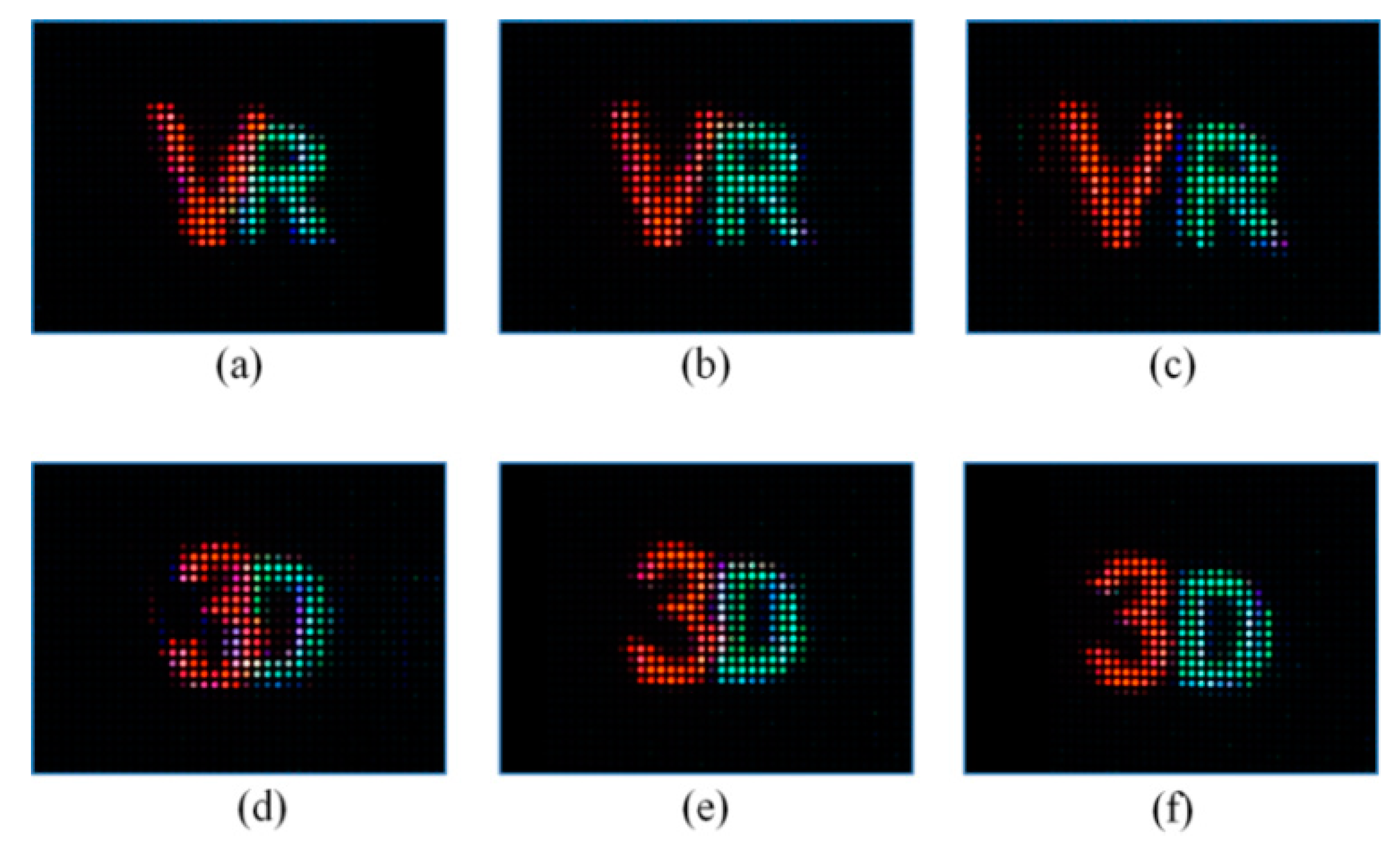
Thus, the DV-EIA generated from the pickup system was loaded on the projector. Then, the divergent beam of the projector containing the information of the DV-EIA was projected onto the CMA. On every convex mirror of the CMA, the left and right-view components of the DV-EIs were separated and reflected back into their viewing directions, and two different 3-D scenes were integrated and displayed on their viewing zones. Figure 14 shows two kinds of optically reconstructed 3-D images of ‘VR’ and ‘3D’ at two different viewing zones on the proposed display system of Figure 14 from the DV-EIA. That is, Figure 14a–c and Figure 14d–f show three kinds of optically reconstructed 3-D images of ‘VR’ and ‘3D’ at the left and right viewing zones, which are viewed from each of the different viewing angles of −19.5°, −10.0°, −3.0 and 3.0, 10.0°, 19.5°, respectively.
As we can see, in the left-hand 3-D image of ‘VR’ viewed from the angle of −19.5°, ‘V’ and ‘R’ images are partially overlapped, where a part of the ‘R’ image is blocked by the image of ‘V’ because the ‘R’ object was originally located back of the ‘R’ object by 50 mm in the pickup process. It means that the reconstructed image of ‘VR’ is a form of 3-D data with depth. In the case of the center image of ‘VR’ of Figure 14b, which is viewed from the angle of −10.0° at the left viewing zone, ‘V’ and ‘R’ images look aligned in parallel, whereas in case of the right-hand image of ‘VR’, ‘V’ and ‘R’ images get a little bit separated from each other since they have different depths. That is, as we move from the left to the center and right directions, the distance difference between the two object images of ‘V’ and ‘R’ increases, which confirms that these object images have depth information. In addition, Figure 14d–f also show the optically reconstructed 3-D images of ‘3D’ at the right viewing zone from the DV-EIA. Those reconstructed ‘3’ and ‘D’ images at three different directions look almost the same as those images in the case of the ‘VR’. These good experimental results of Figure 14 confirm that the proposed system can be applied to the practical dual-view 3-D display.
Moreover, viewing angles for the left and right viewing zones have been measured to range from −19.5° to −3.0° in the left viewing zone, and from 3.0° to 19.5° in the right viewing zone, respectively. These results may also confirm that the proposed system can provide relatively large viewing-angles with a simple optical configuration composed of only a pair of projectors and CMA.
3.5. Experiments with Two Volumetric 3-D Objects
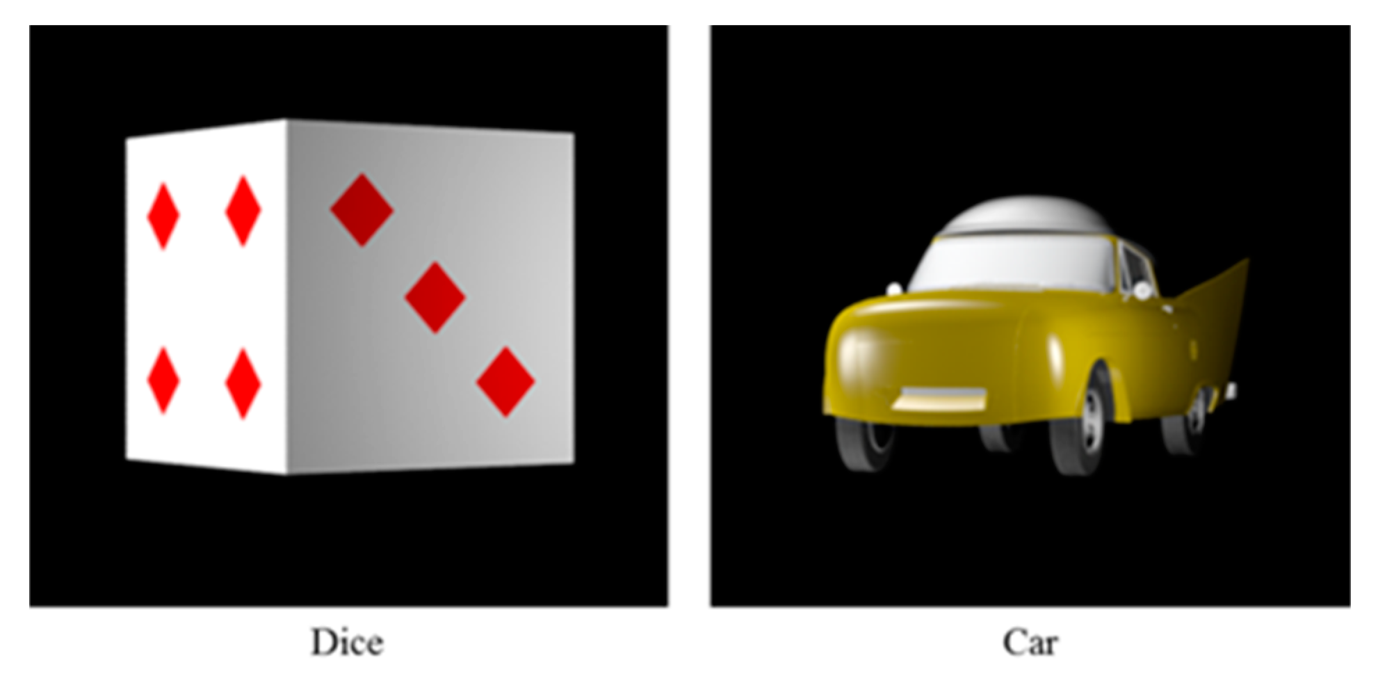
Now, to confirm the feasibility of the proposed system in the practical application, two volumetric 3-D objects of ‘Dice’ and ‘Car’ were used as the test objects in the experiments. Figure 15 shows two kinds of test volumetric 3-D objects of ‘Dice’ and ‘Car’ whose sizes are 25 mm × 25 mm × 25 mm and 25 mm × 21 mm × 50 mm, respectively.
In the experiments, the same pickup lens array was employed. Thus, the pitch and focal length of the pickup lens array were also 1.63 mm and 3.13 mm, respectively, and they were located at the distance of 50 mm from each of the 3-D objects of ‘Dice’ and ‘Car’. Here, the ‘Dice’ and ‘Car’ objects were used for the left and right views, respectively, in the dual 3-D display.
As seen in Equation (5), the viewing angle may change depending on the θkr. Thus, under the condition that the pitch and focal length of the convex mirror are given by 7.32 mm and 7.47 mm, and the CMA is located at the distance of 800 mm from the projector, the maximum K value is 38 since it is limited by half the number of lenses of 77 along the x-direction. As the K value increases, the corresponding viewing angle decreases, whereas it increases as the K value decreases, which may confirm that the K value is inversely related to the viewing angle.
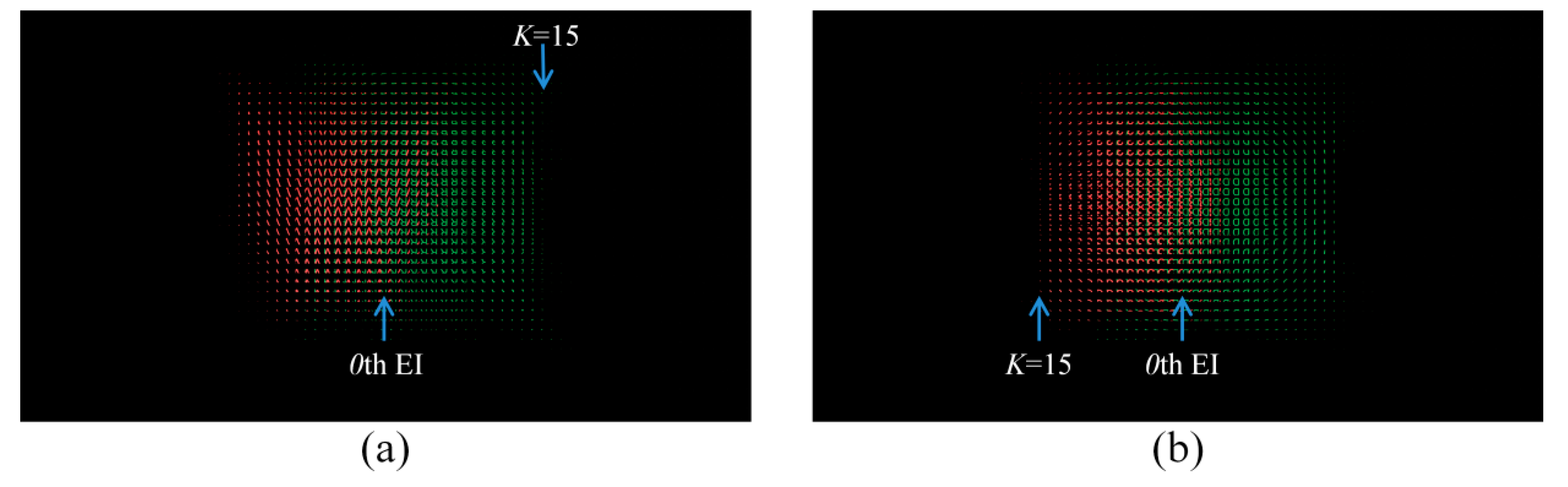
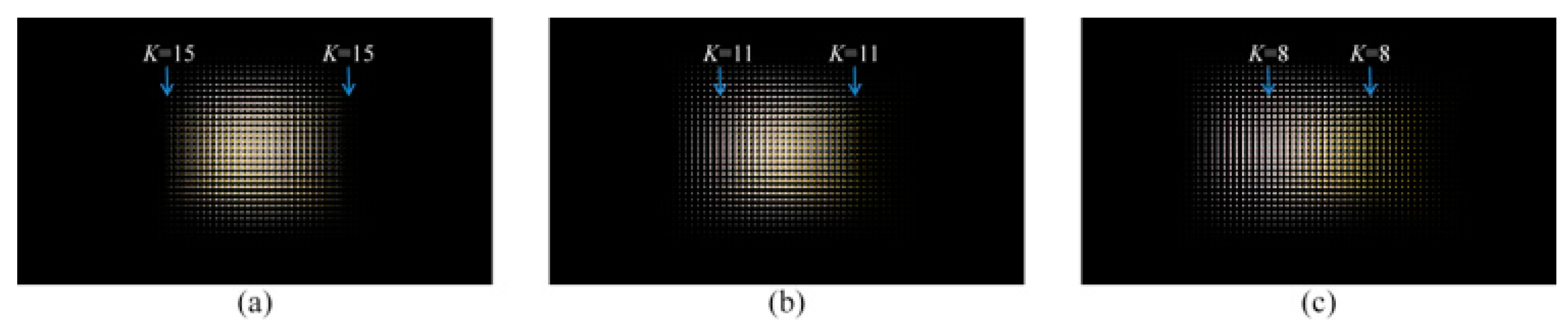
Figure 16 shows the synthesized DV-EIA based on the SSIM method from the captured L-EIA and R-EIA from each of the ‘Dice’ and ‘Car’, respectively, for three cases of K = 15, 11 and 8.
Here, the DV-EIA with 1920 × 1080 pixels is composed of 77 × 44 EIs, where each EI has the resolution of 25 × 25 pixels. Depending on the K values, three kinds of DV-EIAs are synthesized based on the SSIM method, which are shown in Figure 16.
Now, these DV-EIAs can be reconstructed on the proposed display system of Figure 17.
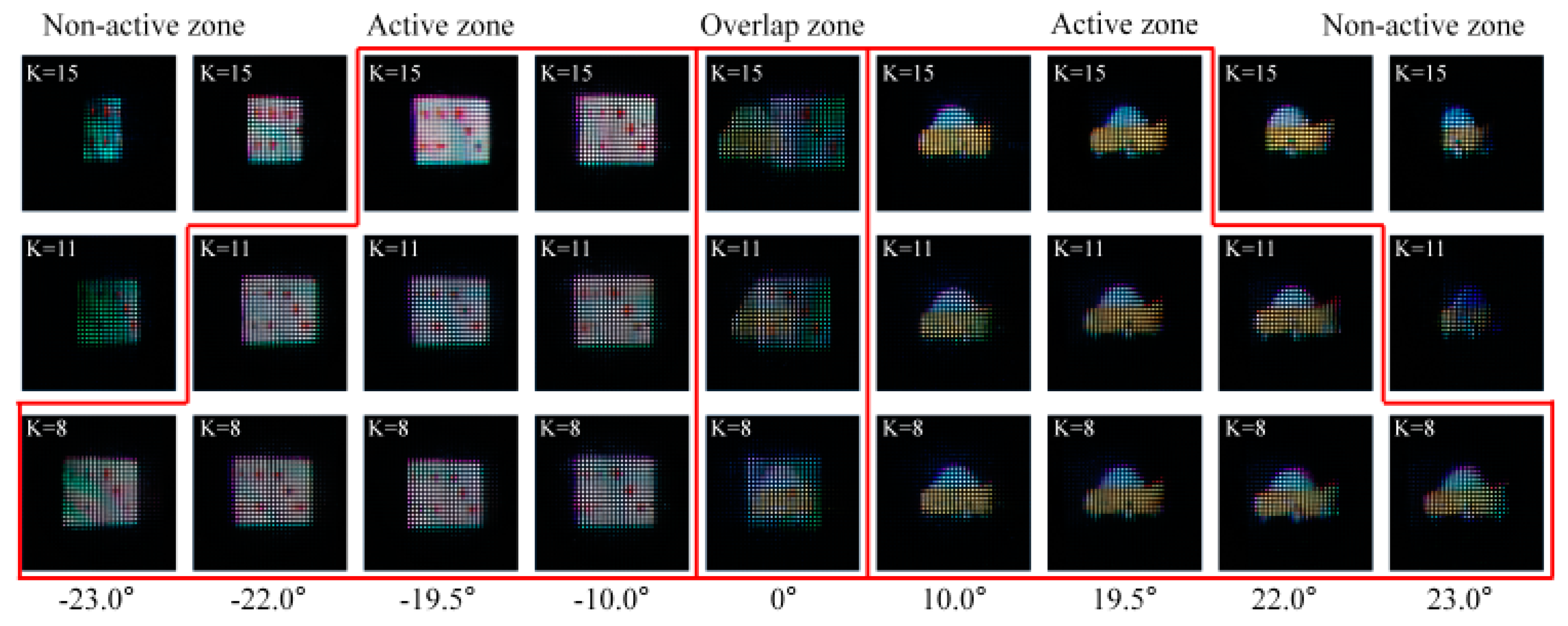
Figure 17 also shows the experimental results of the volumetric 3-D object images of ‘Dice’ and ‘Car’ reconstructed at the left and right viewing zones, respectively, for three cases of the K values.
As seen in Figure 17, for the case of K = 15, the reconstructed object images of ‘Dice’ and ‘Car’ at each of the left and right viewing zones are getting truncated and disappeared just beyond the viewing angle of −19.5° and 19.5°, respectively. These results show that the viewing angles of this dual-view 3-D display system have been measured to be ranged from −19.5° to −3.0° and from 3.0° to 19.5° for the left and right viewing zones, respectively. These measured left and right viewing angles of −19.5° and 19.5° have been found to be almost the same as those calculated values of −20° and 20°, where the error ratio between the calculated and measured viewing angles has been calculated to around 3.0%. Moreover, as we move from the left to the center and center to right directions, different perspectives of the object images of ‘Dice’ and ‘Car’ can be viewed, as seen in Figure 17, which confirms the volumetric 3-D reconstruction of the ‘Dice’ and ‘Car’ objects in the proposed system.
For the case of K = 11, left and right viewing angles are measured to range from −22.0° to −3.0° and from 3.0° to 22.0°, respectively, as seen in Figure 17, where those values are calculated to be −22.2° and 22.2°, respectively, using Equation (5). Thus, the error ratio between the calculated and measured viewing angles has been calculated to be around 3.6%. Here, it must be noted that the left and right viewing angles increased by 3° as the K value decreased to 11 from 15.
For the case of K = 8, left and viewing angles are calculated to be −23.5° and 23.5°, respectively. In addition, those values have been measured to range from -23.0° to -3.0° and from 3.0° to 23.0°, respectively. Thus, these measured left and right viewing angles of −23.0° and 23.0° look almost the same as those of the calculated values of −23.5° and 23.5°. Thus, for the case of K = 8, the error ratio between the calculated and measured viewing angles has been calculated to around 2.1%.
As seen in Figure 17, there are three kinds of viewing zones, such as active, inactive and overlapped regions. Here, the active zones marked with red color represent the DV zones, where we are able to watch the displayed 3-D objects. On the other hand, in other zones including the inactive and overlapped regions, a 3-D object cannot be properly viewed. These experimental results confirm that two different volumetric 3-D object images with their changing perspectives can be successfully reconstructed in both of the left and right viewing zones just like in the case of the previous experiments, and each of the left and right viewing angles can be changed depending on the K value.
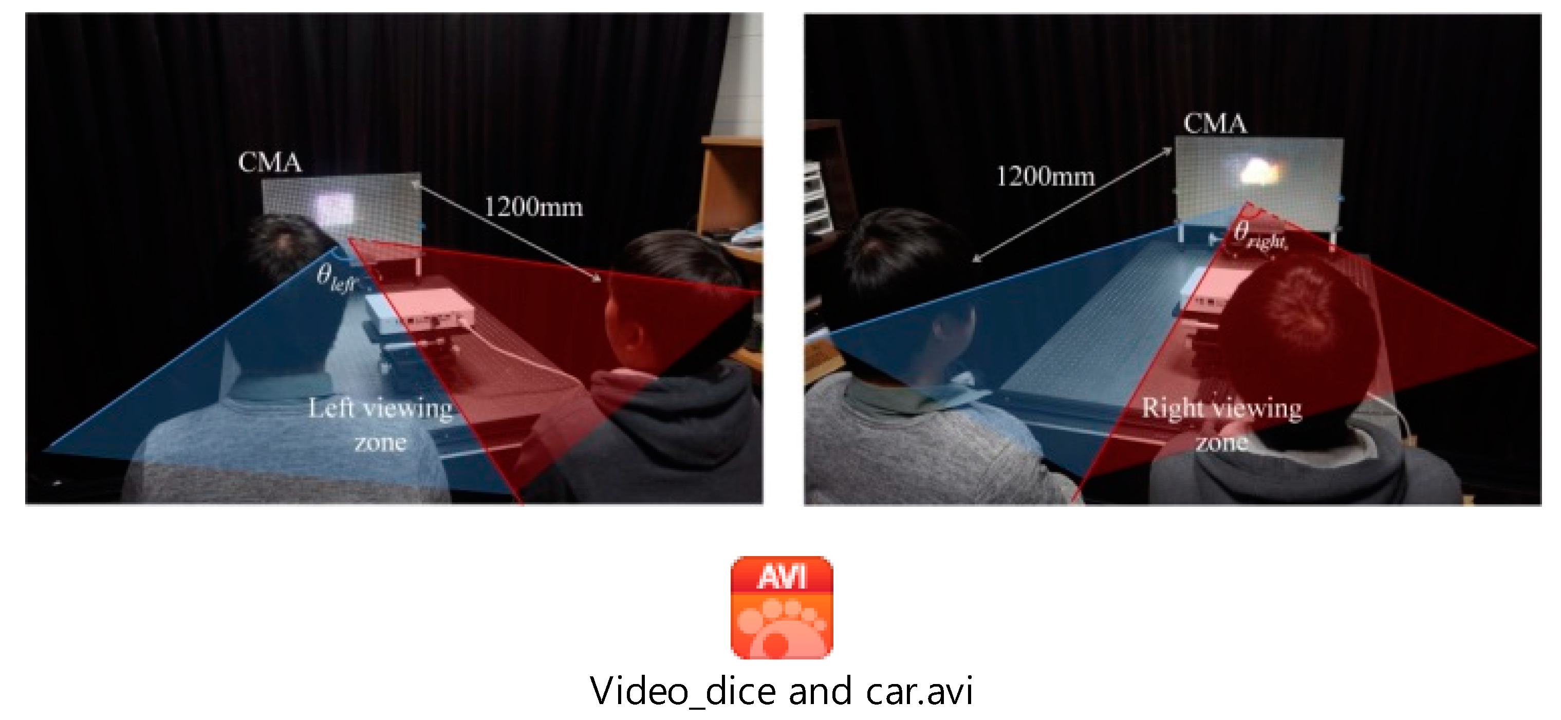
Figure 18 visually shows that two observers sitting at each of the left and right viewing directions are separately watching the two different 3-D object images of ‘Dice’ and ‘Car’ reconstructed from the proposed system, where the projector is located at the distance of 800mm from the CMA, and two observers are seated at the distance of 1200 mm from the CMA.
As seen in Figure 18, each of the left and right viewers can see only the ‘Dice’ or ‘Car’ object images reconstructed at their viewing zones, which means that two different 3-D object images can be separately viewed by two observers who are distinctly sitting in their left and right viewing zones. Experimental results on two test 3-D object images of ‘Dice’ and ‘Car’ with the proposed system have been taken as video files and attached in Figure 18 as a video clip. In the video clip, volumetric 3-D object images of the ‘Dice’ and ‘Car’ with their changing perspectives, which are viewed from −23.0° to −3.0° and from 3.0° to 23.0°, respectively, have been recorded for the case of K = 11. Here, the video frame rate and total recording time are set to be 24 fps (frames per second) and 34 s, respectively. In the video files, each of the left and right 3-D images of the ‘Dice’ and ‘Car’ has been recorded for 17 s, respectively.
As seen in the experimental results of Figure 17 and Figure 18, the resolution and visibility of the reconstructed 3-D images still look somewhat degraded since the fill factor of the elemental convex mirror is low [33]. Thus, using elemental mirrors with much-enhanced fill factors can enhance the resolution and visibility of those 3-D images.
4. Conclusions
In this paper, a new type of the viewing angle-enhanced 3-D dual-view display based on the CMA-DPII system is proposed. Two kinds of elemental image arrays (EIAs) are captured from each of the two 3-D objects and synthesized into a single dual-view EIA (DV-EIA) with the selective sub-image mapping (SSIM) scheme. Then, a divergent beam of the projector containing this DV-EIA image is directly projected onto the CMA, where left and right-view components of the DV-EIA are separately reflected back into their viewing directions and finally form the two different 3-D images displayed on their viewing zones. From the ray-optical analysis with the parallel-ray-approximation method and successful experimental results with the test 3-D objects on an implemented 22′′DV 3-D display prototype, the feasibility of the proposed system is confirmed in the practical application.
Author Contributions
Conceptualization, H.-M.C., J.-G.C., E.-S.K.; methodology, H.-M.C., J.-G.C.; validation H.-M.C., J.-G.C.; formal analysis, H.-M.C.; writing-original draft preparation, H.-M.C., J.-G.C.; writing-review and editing, E.-S.K.; funding acquisition, E.-S.K.
Funding
This research was partially funded by Basic Science Research Program through the National Research Foundation of Korea (NRF) supported by the Ministry of Education (No. 2018R1A6A1A03025242) and supported by the MSIT (Ministry of Science and ICT), Korea, under the ITRC support program (IITP-2017-01629) supervised by the IITP.
Conflicts of Interest
The authors declare no conflict of interest.
References
- Gulick, S., Jr. Dual-View Imaging Product. U.S. Patent 5757550 A, 26 May 1998. [Google Scholar]
- Kuhlman, F.F.; Harbach, A.P.; Parker, R.D.; Sarma, D.H.R. Dual View Display System Using a Transparent Display. U.S. Patent 8362992 B2, 29 January 2013. [Google Scholar]
- Yamamoto, H.; Kimura, T.; Matsumoto, S.; Suyama, S. Viewing-Zone Control of Light-Emitting Diode Panel for Stereoscopic Display and Multiple Viewing Distances. J. Disp. Technol. 2010, 6, 359–366. [Google Scholar] [CrossRef]
- Kuhlman, F.F.; Harbach, A.P.; Sarma, D.H.R.; Sultan, M.F. Dual View Display System. U.S. Patent 8363325 B2, 29 January 2013. [Google Scholar]
- Yamane, T.; Konishi, T.; Nagamoto, S.; Tanaka, S.; Uehara, S.; Kamoto, M.; Ohshima, T. Fall 2005 DUAL AVN development. FUJITSU Ten Tech. J. 2006, 26, 17–22. [Google Scholar]
- Mather, J.; Montgomery, D.J.; Winlow, R.; Bourhill, G.; Barrett, N.W. Multiple-View Directional Display. U.S. Patent US7580186 B2, 25 August 2009. [Google Scholar]
- Sharp. Available online: http://www.sharp-world.com/corporate/news/0507.html (accessed on 19 March 2019).
- Mather, J.; Barratt, N.; Kean, D.U.; Walton, E.J.; Bourhill, G.; Powell, T.W. Directional Backlight, a Multiple View Display and a Multi-Direction Display. U.S. Patent 8154686 B2, 10 April 2012. [Google Scholar]
- Mather, J.; Smith, N.J. Multiple View Display. U.S. Patent 9274345 B2, 1 March 2016. [Google Scholar]
- Chen, C.Y.; Hsieh, T.Y.; Deng, Q.L.; Su, W.C.; Cheng, Z.S. Design of a novel symmetric microprism array for dual-view display. Displays 2010, 31, 99–103. [Google Scholar] [CrossRef]
- Lanman, D.; Wetzstein, G.; Hirsch, M.; Heidrich, W.; Raskar, R. Polarization Fields: Dynamic Light Field Display using Multi-Layer LCDs. In Proceedings of the 2011 SIGGRAPH Asia Conference, Hong Kong, China, 12–15 December 2011; pp. 1–9. [Google Scholar]
- Mather, J.; Jones, L.P.; Gass, P.; Imai, A.; Takatani, T.; Yabuta, K. Potential improvements for dual directional view displays. Appl. Opt. 2014, 53, 769–776. [Google Scholar] [CrossRef] [PubMed]
- Hsieh, C.T.; Shu, J.N.; Chen, H.T.; Huang, C.Y.; Tian, C.J.; Lin, C.H. Dual-view liquid crystal display fabricated by patterned electrodes. Opt. Express 2012, 20, 8641–8648. [Google Scholar] [CrossRef]
- Hsieh, C.T.; Li, G.Y.; Wu, T.T.; Huang, C.Y.; Tien, C.J.; Lo, K.Y.; Lin, C.H. Twisted Nematic Dual-View Liquid Crystal Display Based on Patterned Electrodes. IEEE J. Disp. Technol. 2014, 10, 464–469. [Google Scholar] [CrossRef]
- Tang, P.; Cui, J.-P.; Liang, D.; Wang, Q.-H. Spatial-multiplexed dual-view display using blue phase liquid crystal. SID Symp. Dig. Tech. Pap. 2014, 45, 1389–1391. [Google Scholar] [CrossRef]
- Kean, D.U.; Montgomery, D.J.; Mather, J.; Bourhill, G.; Jones, G.R. Parallax Barrier and Multiple View Display. U.S. Patent 7154653 B2, 26 December 2006. [Google Scholar]
- Krijn, M.; de Zwart, S.T.; de Boer, D.K.G.; Willemsen, O.H.; Sluijter, M. 2D/3D displays based on switchable lenticulars. J. SID 2008, 16, 847–855. [Google Scholar]
- Cui, J.P.; Li, Y.; Yan, J.; Cheng, H.C.; Wang, Q.H. Time-multiplexed dual-view display using a blue phase liquid crystal. J. Disp. Technol. 2013, 9, 87–90. [Google Scholar] [CrossRef]
- Silva, V.N.H.; Stoenescu, D.; Nassour, T.C.; de la Rivière, J.-B.; Tocnaye, J.-L. Ghosting Impingements in 3D Dual-View Projection Systems. J. Disp. Technol. 2014, 10, 540–547. [Google Scholar] [CrossRef]
- Wu, F.; Deng, H.; Luo, C.G.; Li, D.H.; Wang, Q.H. Dual-view integral imaging three-dimensional display. Appl. Opt. 2013, 52, 4911–4914. [Google Scholar] [CrossRef]
- Wu, F.; Wang, Q.H.; Luo, C.G.; Li, D.H.; Deng, H. Dual-view integral imaging 3D display using polarizer parallax barriers. Appl. Opt. 2014, 53, 2037–2039. [Google Scholar] [CrossRef]
- Wang, Q.-H.; Ji, C.-C.; Li, L.; Deng, H. Dual-view integral imaging 3D display by using orthogonal polarizer array and polarization switcher. Opt. Express 2016, 24, 9–16. [Google Scholar] [CrossRef]
- Jeong, J.; Lee, C.K.; Hong, K.; Yeom, J.; Lee, B. Projection-type dual-view three-dimensional display system based on integral imaging. Appl. Opt. 2014, 53, 12–18. [Google Scholar] [CrossRef]
- Jang, J.-S.; Javidi, B. Three-dimensional projection integral imaging using micro-convex-mirror arrays. Opt. Express 2004, 12, 1077–1086. [Google Scholar] [CrossRef] [PubMed]
- Okui, M.; Arai, J.; Nojiri, Y.; Okano, F. Optical screen for direct projection of integral imaging. Appl. Opt. 2006, 45, 9132–9139. [Google Scholar] [CrossRef] [PubMed]
- Kang, H.-H.; Lee, J.-H.; Kim, E.-S. Enhanced compression rate of integral images by using motion-compensated residual images in three-dimensional integral-imaging. Opt. Express 2012, 20, 5440–5459. [Google Scholar] [CrossRef]
- Xiaoya, Z.; Dong, X.; Yongsheng, W.; He, S. A simple parallel ray approximation based stochastic channel model for MIMO UWB systems with measurement verification. In Proceedings of the 2010 International Conference on Communications and Mobile Computing, Shenzhen, China, 12–14 April 2010; pp. 102–106. [Google Scholar]
- Tiberi, G.; Bertini, S.; Malik, W.Q.; Monorchio, A.; Edwards, D.J.; Manara, G. Analysis of realistic ultrawideband indoor communication channels by using an efficient ray-tracing based method. IEEE Trans. Antennas Propag. 2009, 57, 777–785. [Google Scholar] [CrossRef]
- Miron, D.B. Small Antenna Design; NEWNES: Boston, MA, USA, 2006; pp. 255–256.
- Sard, A. Linear Approximation; American Mathematical Society: Providence, RI, USA, 1963; p. 83. [Google Scholar]
- Stern, A.; Javidi, B. Three-dimensional image sensing, visualization, and processing using integral imaging. Proc. IEEE 2006, 94, 591–607. [Google Scholar] [CrossRef]
- Jang, J.-Y.; Shin, D.; Lee, B.-G.; Kim, E.-S. Multi-projection integral imaging by use of a convex mirror array. Opt. Lett. 2014, 39, 2853–2856. [Google Scholar] [CrossRef] [PubMed]
- Park, S.; Song, B.-S.; Min, S.-W. Analysis of Image Visibility in Projection-type Integral Imaging System without Diffuser. J. Opt. Soc. Korea 2010, 14, 121–126. [Google Scholar] [CrossRef]
Figure 1.
Overall block-diagram of the proposed system: (a) Pickup of two elemental image arrays (EIAs), (b) generation of the dual-view elemental image array (DV-EIA) based on the selective sub-image mapping (SSIM) method, (c) reconstruction of the dual-view (DV) 3-D images in their viewing zones.
Figure 1.
Overall block-diagram of the proposed system: (a) Pickup of two elemental image arrays (EIAs), (b) generation of the dual-view elemental image array (DV-EIA) based on the selective sub-image mapping (SSIM) method, (c) reconstruction of the dual-view (DV) 3-D images in their viewing zones.

Figure 2.
Two types of the EIA pickup systems: (a) Off-axis pickup, (b) on-axis pickup.

Figure 3.
Two captured EIAs from each of the two different 3-D objects of ‘Dice’ and ‘Car’ on the on-axis integral imaging system (a) captured EIA from the ‘Dice’ (b) captured EIA from the ‘Car’.
Figure 3.
Two captured EIAs from each of the two different 3-D objects of ‘Dice’ and ‘Car’ on the on-axis integral imaging system (a) captured EIA from the ‘Dice’ (b) captured EIA from the ‘Car’.

Figure 4.
Generation of the DV-EIA with the left elemental image array (L-EIA) and left elemental image array (R-EIA) based on the SSIM method.
Figure 4.
Generation of the DV-EIA with the left elemental image array (L-EIA) and left elemental image array (R-EIA) based on the SSIM method.

Figure 5.
Optical configuration of the direct-projection integral imaging system for the DV 3-D display.
Figure 5.
Optical configuration of the direct-projection integral imaging system for the DV 3-D display.

Figure 6.
Optical geometry for the ray-optical analysis of the proposed system based on the parallel-ray-approximation (PRA) method.
Figure 6.
Optical geometry for the ray-optical analysis of the proposed system based on the parallel-ray-approximation (PRA) method.

Figure 7.
Optical configuration of the bundle of parallel rays incident to the Kth convex mirror from the pinhole projector.
Figure 7.
Optical configuration of the bundle of parallel rays incident to the Kth convex mirror from the pinhole projector.

Figure 8.
Optical configuration for analyzing the dual-viewing zones of the proposed system.

Figure 9.
Optical configuration of the integrated points of 3-D object images in the left/right viewing zones.
Figure 9.
Optical configuration of the integrated points of 3-D object images in the left/right viewing zones.

Figure 10.
Experimental setup of the proposed system.

Figure 11.
(a) Two test 3-D objects composed of two pairs of 2-D images with different depths (‘VR’ and ‘3D’) and (b) on-axis integral imaging pickup system.
Figure 11.
(a) Two test 3-D objects composed of two pairs of 2-D images with different depths (‘VR’ and ‘3D’) and (b) on-axis integral imaging pickup system.

Figure 12.
Two EIAs captured from each 3-D object of the ‘VR’ and ‘3D’: (a) L-EIA captured from the ‘VR’, (b) R-EIA captured from the ‘3D’.
Figure 12.
Two EIAs captured from each 3-D object of the ‘VR’ and ‘3D’: (a) L-EIA captured from the ‘VR’, (b) R-EIA captured from the ‘3D’.

Figure 13.
Generation of the DV-EIA with L-EIA and R-EIA based on SSIM: (a) L-EIA and R-EIA, (b) left sub-image array (L-SIA) and right sub-image array (R-SIA), (c) dual-view right sub-image array (DV-SIA), and (d) DV-EIA.
Figure 13.
Generation of the DV-EIA with L-EIA and R-EIA based on SSIM: (a) L-EIA and R-EIA, (b) left sub-image array (L-SIA) and right sub-image array (R-SIA), (c) dual-view right sub-image array (DV-SIA), and (d) DV-EIA.

Figure 14.
3-D images of ‘VR’ viewed from three different viewing angles of (a) −21.0°, (b) −10.0° and (c) −3.0°, and those of ‘3D’ viewed from those of (d) 3.0°, (e) 10.0° and (f) 21.0°, respectively.
Figure 14.
3-D images of ‘VR’ viewed from three different viewing angles of (a) −21.0°, (b) −10.0° and (c) −3.0°, and those of ‘3D’ viewed from those of (d) 3.0°, (e) 10.0° and (f) 21.0°, respectively.

Figure 15.
Two test volumetric 3-D objects of ‘Dice’ and ‘Car’.

Figure 16.
Synthesized DV-EIA for the ‘Dice’ and ‘Car’ objects with different K values: (a) K = 15, (b) K = 11 and (c) K = 8.
Figure 16.
Synthesized DV-EIA for the ‘Dice’ and ‘Car’ objects with different K values: (a) K = 15, (b) K = 11 and (c) K = 8.

Figure 17.
Reconstructed dual-view 3-D object images of ‘Dice’ and ‘Car’ at the left and right viewing zones, respectively, for three cases of the K values.
Figure 17.
Reconstructed dual-view 3-D object images of ‘Dice’ and ‘Car’ at the left and right viewing zones, respectively, for three cases of the K values.

Figure 18.
Photos of two observers watching two different 3-D object images of ‘Dice’ and ‘Car’ at the left and right viewing zones with the optical setup of the proposed system.
Figure 18.
Photos of two observers watching two different 3-D object images of ‘Dice’ and ‘Car’ at the left and right viewing zones with the optical setup of the proposed system.


Table 1.
Detailed specifications of the pickup and display setups.
| Elemental Image Array (EIA) | - Resolution - Number of EIs - Resolution of each EI | 1920 × 1080 pixels 77 × 44 25 × 25 pixels |
| Projector (LG PF85K) | - Diverging angle (2θp) - Distance to the CMA | 39° 800 mm |
| Convex mirror array (CMA) | - Pitch & focal length - arctan(1/2(f#)) - Number of CMAs | 7.47 mm and 7.32 mm 27.0° 77 × 44 |
| Pickup lens array | - Pitch & focal length - Number of lenses - Distance from the camera | 1.63 mm and 3.13 mm 77 × 44 160 mm |
| Viewing angle | - Left viewing-angle - Right viewing-angle | 20.0° 20.0° |
| Test object (‘VR’) | - Front depth - Rear depth | 50 mm 100 mm |
| Test object (‘3D’) | - Front depth - Real depth | 50 mm 100 mm |
© 2019 by the authors. Licensee MDPI, Basel, Switzerland. This article is an open access article distributed under the terms and conditions of the Creative Commons Attribution (CC BY) license (http://creativecommons.org/licenses/by/4.0/).
Share and Cite
MDPI and ACS Style
Choi, H.-M.; Choi, J.-G.; Kim, E.-S. Dual-View Three-Dimensional Display Based on Direct-Projection Integral Imaging with Convex Mirror Arrays. Appl. Sci. 2019, 9, 1577. https://doi.org/10.3390/app9081577
AMA Style
Choi H-M, Choi J-G, Kim E-S. Dual-View Three-Dimensional Display Based on Direct-Projection Integral Imaging with Convex Mirror Arrays. Applied Sciences. 2019; 9(8):1577. https://doi.org/10.3390/app9081577
Chicago/Turabian StyleChoi, Hee-Min, Jae-Gwan Choi, and Eun-Soo Kim. 2019. "Dual-View Three-Dimensional Display Based on Direct-Projection Integral Imaging with Convex Mirror Arrays" Applied Sciences 9, no. 8: 1577. https://doi.org/10.3390/app9081577
Note that from the first issue of 2016, this journal uses article numbers instead of page numbers. See further details here.