Article

A Modular Architecture of Command-and-Control Software in Multi-Sensor Systems Devoted to Public Security

1
ENEA-Italian National Agency for New Technologies, Energy and Sustainable Economic Development, 00123 Rome, Italy
2
TNO-Netherlands Organisation for Applied Scientific Research, 2597 The Hague, The Netherlands
3
VTT-Technical Research Centre of Finland, 33101 Tampere, Finland
4
ATAC-Azienda per la Mobilità di Roma Capitale S.p.A, 00176 Rome, Italy
*
Author to whom correspondence should be addressed.
Information 2023, 14(3), 162; https://doi.org/10.3390/info14030162
Submission received: 28 January 2023 / Revised: 14 February 2023 / Accepted: 1 March 2023 / Published: 3 March 2023
(This article belongs to the Special Issue IoT-Based Systems for Safe and Secure Smart Cities)

Abstract

:
Preventing terrorist attacks at soft targets has become a priority for our society. The realization of sensor systems for automatic threat detection in crowded spaces, such as airports and metro stations, is challenged by the limited sensing coverage capability of the devices in place due to the variety of dangerous materials, to the scanning rate of the devices, and to the detection area covered. In this context, effectiveness of the physical configuration of the system based on the detectors used, the coordination of the sensor data collection, and the real time data analysis for threat identification and localization to enable timely reactions by the security guards are essential requirements for such integrated sensor-based applications. This paper describes a modular distributed architecture of a command-and-control software, which is independent from the specific detectors and where sensor data fusion is supported by two intelligent video systems. Furthermore, the system installation can be replicated at different locations of a public space. Person tracking and later re-identification in a separate area, and tracking hand-over between different video components, provide the command-and-control with localization information of threats to timely activate alarm management and support the activity of subsequent detectors. The architecture has been implemented for the NATO-funded DEXTER program and has been successfully tested in a big city trial at a metro station in Rome both when integrated with two real detectors of weapons and explosives and as a stand-alone system. The discussion focuses on the software functions of the command-and-control and on the flexibility and re-use of the system in wider settings.

1. Introduction

The occurrence of recent terrorist attacks involving explosives in underground stations and airports, such as in Brussels, Zaventem, 2013 (https://www.epc.eu/en/Publications/The-fall-out-from-the-Brussels~1d2eb4 (accessed on 20 January 2023)) (suicide bombers) and Parson Green, London, 2017 (https://assets.publishing.service.gov.uk/government/uploads/system/uploads/attachment_data/file/776162/HC1694_The2017Attacks_WhatNeedsToChange.pdf (accessed on 20 January 2023)) (IED detonation), has demonstrated that surveillance systems for soft targets in complex scenarios still do not ensure a sufficient level of security. The difficulties are the huge volume of passengers to keep under control, the vast urban areas of interest, and the ability of terrorists to conceal the threat and to maintain a behavior hardly discernable from normal commuters. The availability of instruments for automatic detection of weapons and explosives (see, for example, [1,2]) and of intelligent video systems for persons tracking [3,4], and the maturity of IoT-technology for smart city applications [5], allow one to conceive novel early threat detection systems that activate alarm management processes.
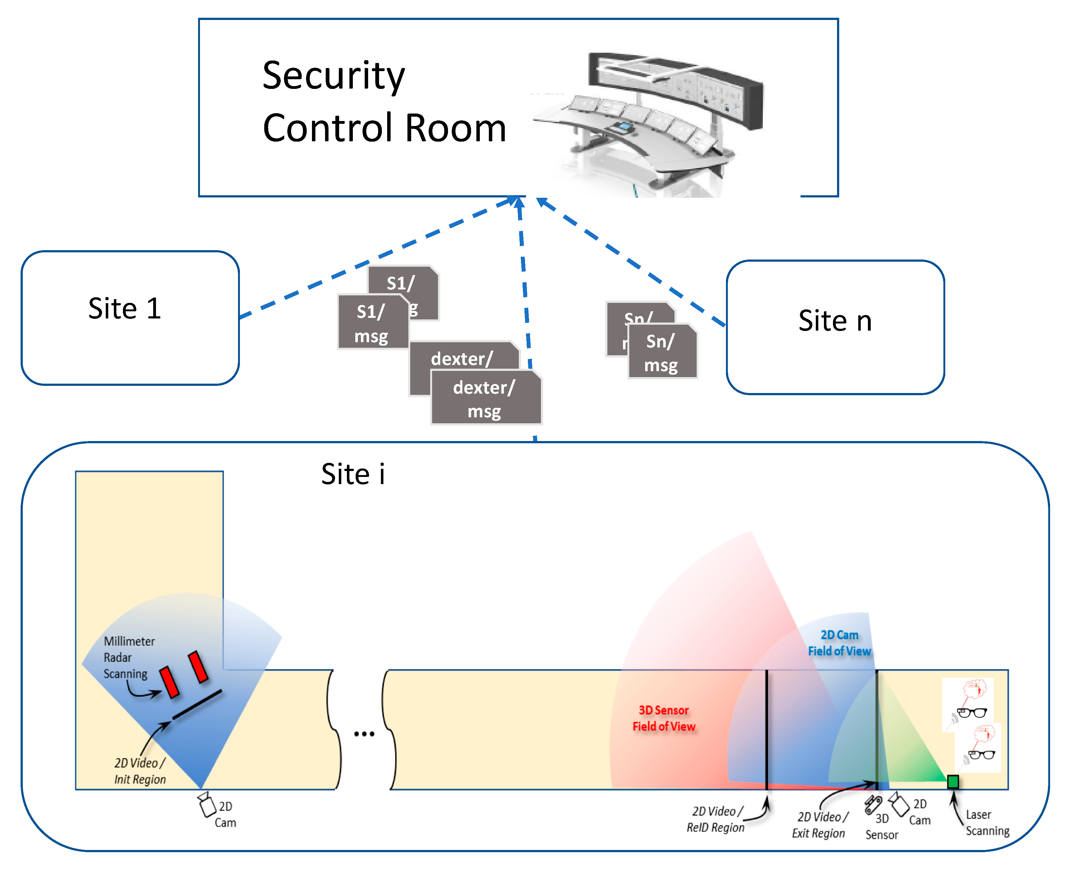
The function of the command-and-control (C&C) software in such a system is the orchestration of the plurality of sensors, deployed in various delimited areas of a public space and targeting potential terroristic persons, e.g., wearing explosive objects hidden under clothes or inside bags. The technological challenge is twofold: to optimize the work of agents on field by providing security checks in a non-intrusive manner and to support localization of the threat in the crowd; also, the second challenge is to strengthen the operations at the security control room of a critical infrastructure through automatic communication of alarms and of any relevant information for the police. The first challenge requires one to integrate and fuse detections of different sensors that produce data in real time and that work unnoticeable to the persons passing through the observed locations. The second requires a robust real time system for automatic alert generation without impacting the passengers’ flow, and which can innovate existing situational awareness systems devoted to public security. Indeed, the control work in security rooms currently is mostly based on direct observation by the operators through the video cameras deployed at different sites of the infrastructure, and alarm communication and management are very much human-based processes.
This paper describes a modular distributed architecture of a command-and-control software, which is independent from the specific detectors and where sensor data fusion is supported by two intelligent video systems. One allows re-identification and tracking of a person previously identified by another camera, and the other delivers position prediction of a person near a sensor to reduce detection misses. Thus, the architecture can fuse sensor detections of the same person realized in non-adjacent sites of a big area and also allows one to set up a network of installations covering different sites of the same infrastructure.
Other than informing the security room in real time, the C&C automatically supplies alerts to a indoor localization system dispatching images of the person to be altered on the smart glasses worn by the security guards, thus enabling their timely reaction on the field.
The architecture comprising the C&C and the two video systems, named INSTEAD (Integrated SysTem for Early Thread Detection), has been implemented for the NATO-SPS funded [6] DEXTER program and has been successfully tested in a Big City Trial (BCT) at a metro station in Rome, both when integrated with two real detectors of weapons and explosives and as a stand-alone system. The assessment of INSTEAD in the controlled trials is detailed in [7], whereas a preliminary study of INSTEAD was presented in [8].
This paper describes the software architecture of the C&C implementation, which is modular, as it integrates completely decoupled components. Two generic types of video sensor data fusion methods are implemented: one suitable for sensors exclusively targeted on movable objects and the other for sensor systems that use their own video system to work towards a target. Thus, these methods can be applied to various sensors, and not only those used for DEXTER. The loosely coupled component communication model and a generic data structure for sensor messages allow extension of the software with additional components. The software design and the results of further experiments performed in the real environment using less constrained scenarios than those presented in [7] allow one to demonstrate flexibility and re-use of the system in different deployments. Other relevant quality aspects of the software are also discussed.
The rest of the paper is organized as it follows. Section 2 presents related work. Section 3 provides the reference system architecture where the C&C has been implemented as part of the INSTEAD system, and the description of the DEXTER deployment is used as a case study. Then, the C&C is detailed in Section 4. Section 5 presents the experimental results, while a discussion on quality aspects of the system is presented in Section 6. Finally, Section 7 summarizes the conclusion and suggestions for future work.

2. Related Work

The present work includes data fusion methods from sensor data aiming at human activities recognition. These topics, even separately, have been widely treated by the literature as follows.
An increasing number of data fusion approaches depend on the sources of data and the environmental constraints. Papčo et al. [9], for instance, proposed an extension of the notion of deviation-based aggregation function tailored to aggregate multidimensional data to be used in case temporal constraints are strict. Zhang et al. [10] presented a survey, including a comprehensive investigation on how to use information fusion to leverage edge data for intelligence in four relevant scenarios: multisource information fusion, real-time information fusion, event-driven information fusion, and context-aware information fusion. Rough set theory (RST) deals with classification issues concerning uncertain data modeling. A survey covering multi-source information fusion (MSIF) based on rough set theory was presented in [11]. As in these works, we use data fusion algorithms, but we have different environmental constraints due to the specific application for public security.
Several works specifically addressed fusion of data from sensors. Yang et al. [12] proposed a series of tensor-based knowledge fusion and reasoning models for cyber–physical–social systems, which integrate cyber space, physical space, and social space. Potential use and opportunities of data fusion techniques in IoT-enabled applications for physical activity recognition and measure are investigated in a systematic review by Qi et al. [13]. Lau et al. [14] introduced a multi-perspective classification of the data fusion to evaluate the smart city applications in order to evaluate selected applications in different smart city domains. With respect to data from sensors, most of the data of the system we developed originated from physical detectors that are error-prone. Hence, the evaluation of the proposed C&C is critical, since it should distinguish between the errors due to detectors and those to the data fusion algorithm. This aspect has been discussed by Bouma et al. [7].
Among the most significant works on human activity recognition based on noninvasive environmental sensors, we cite Li et al. [15], who proposed a methodology for a single user’s daily behavior recognition that can adaptively constrain the sensor noise. Qiu et al. [16] presented a holistic approach to develop a full understanding of the fusion methods of wearable sensors data for human activity recognition applications. Finally, Al-Sa’d et al. [3] proposed a privacy-preserving solution for crowd monitoring through cameras aimed at adaptive social distance estimation. We share with this last work the goal of the experimentation that entails the system’s ability in person detection and localization.
Another aspect of the work concerns the definition of a flexible architectural framework for multi-sensor systems for real time defense applications. In this field, the Sensing for Asset Protection with Integrated Electronic Networked Technology (SAPIENT) architectural framework was proposed in [17], and its Interface Control Document (ICD) [18] has been recently evaluated as an interoperability standard for multi-sensor counter-UAS systems. SAPIENT has been conceived as a general-purpose framework where both the type of sensors and the decision-making logic are flexible. Modules are of two types: Agent Sensor Modules (ASM), each managing communication with one sensor; and High-Level Decision Making Modules (HLDMM), which perform data fusion and define reactions. The architecture is database-centric. Adding a new sensor in SAPIENT requires implementing a specific data management agent devoted to storing the sensor detection data in a central database. The same is required when adding a new instance of HLDMM.
The INSTEAD architecture has been conceived to integrate autonomous sensor-based systems, where decision-making at sensor/component level is actually performed before message generation for the C&C. Additionally, in INSTEAD, performance issues have been carefully considered at design time due to strict real-time requirements. Therefore, data fusion and threat detection are performed in memory with the goal to increase the system performance. For a similar reason, the message payload of the components uses a simple JavaScript Object Notation (JSON)-based [19] structure, which is less verbose than that based on XML [20] defined by SAPIENT.
A comparison of the methods used by the two-dimensional video (2D Video) and the three-dimensional video (3D Video) systems to support data fusion with respect to other works is also relevant.
With respect to 2D Video person localization and re-identification capability, common deep learning technology [21] can reach high rank-1 accuracy on a large public dataset [22], but it includes facial information, and, in general, it does not generalize well to other environments, which makes it less suitable for practical applications. The 2D Video pipeline used in the INSTEAD architecture applies a new strategy for rapid Re-ID retraining [23] on anonymized person detections [24] to enhance privacy and increase flexibility for deployment in new environments.
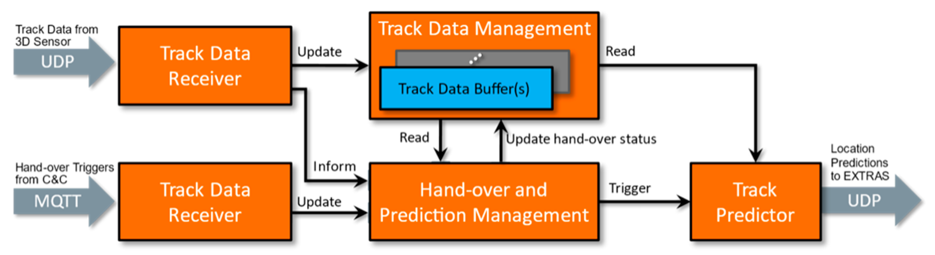
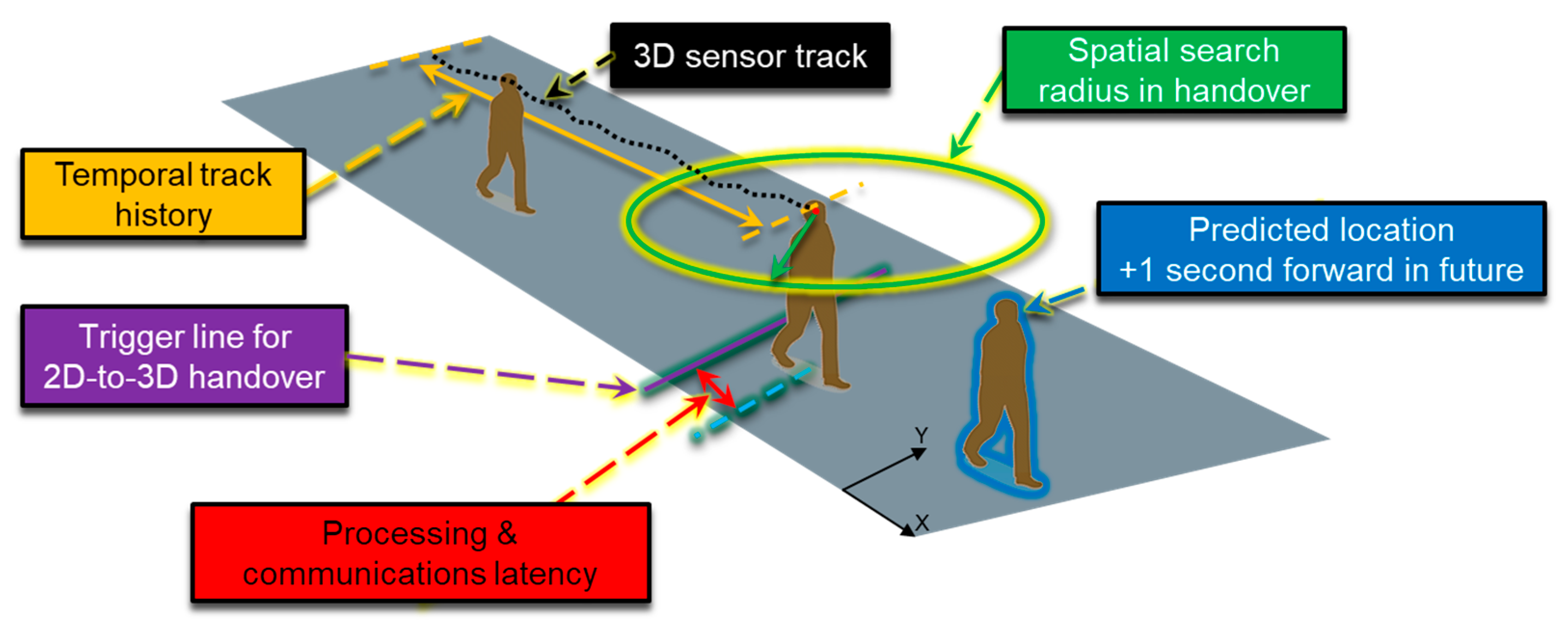
Tracking person movements using three-dimensional sensor approaches instead of two-dimensional cameras can offer improved tracking ability and activity estimation accuracy [25]. Accurate tracking of human movement is essential in multi-sensor systems, where the target is identified with one system, and the confirmation or final analysis is performed with another. High tracking accuracy ensures, especially in crowded spaces, that a hand-over between sensor systems is successful and that the effective analysis is performed on the correct target person. High accuracy requirement is even higher if person movement prediction is required for compensating delays caused by, for example, network communications latencies or adjustment delays in mechanical operations of pan-tilt-zoom (PTZ) sensors.
More generally, Stone Soup is a very recent architectural framework devoted to systems for tracking and state estimation of moving objects. This is an open-source software project that produced a first release in 2019 and which is evolving thanks to a collaborative development, as described in the paper by Barr et al. [26]. In particular, Stone Soup is primarily promoted as a generic and modular architectural framework for upload, test, and benchmark, which are different types of tracking solutions. To this aim, various implementations are provided in the framework. Person tracking in wide areas based on re-identification is not currently available in the framework, and the possibility to define workflows combining different video sensor data fusion activities as those implemented by INSTEAD is not straightforward. This workflow is implemented by the C&C in a declarative logic-based language for data-stream processing, whereas Stone Soup is a Python project, providing class-based structures and programming interfaces to implement modules. The possibility of interface with Stone Soup could be an interesting direction for future work.
The INSTEAD system has been previously presented in [7,8], which illustrate different technical aspects of the system as follows. The first paper [7] contains more details on the techniques for video systems person tracking hand-over with experiments for later integration in the INSTEAD architecture. The second paper [8] contains more details about the INSTEAD deployment in DEXTER system and focuses on detection accuracy results at BCT. The technical details of the re-identification method are provided in other papers [23,
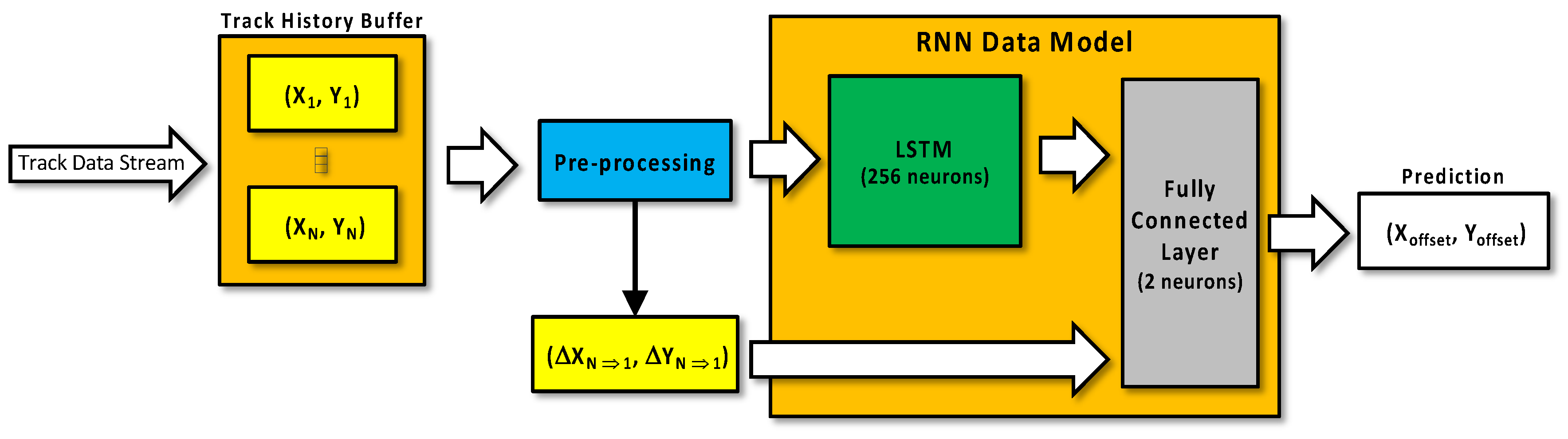
24]. This paper focuses on the INSTEAD internal architecture, and, in particular, it expands on the Command and Control subsystem, with the implementation of the data fusion of the alarm management and of the communication middleware. It further expands on the RNN-based implementation of the 3D Video system. Quality aspects of the architecture and reuse for other scenarios and/or to multi-sensor systems are presented.

3. Threat Detection System for the Security of Critical Infrastructures

The function of the C&C system in a multi-sensor system for the security in public spaces, which is the integration and orchestration of the different tasks of the human and technological components of such a system.
Figure 1 illustrates the role of the C&C described in this paper in a reference architecture of a multi-sensor system for early threat detection deployed at a critical infrastructure. This consists of various site-specific installations of a threat detection system, each integrating sensors deployed in pre-defined corridors of the critical infrastructure, which supply threat information to a security control room.
In this architecture, the C&C has two functions: collecting and visualizing threat information generated at the various sites for the operators in the security control room; and local coordination of the detection activity performed by the sensor systems, with real time data fusion for alarm management by the security agents on the field. For the second function, the C&C leverages person identification and tracking of two intelligent video-systems, a 2D Video system and a 3D Video system, with cameras disposed near the sensors, and of an indoor localization system for the coordination of security agents informed of the threat by means of smart glasses. Such an integrated system is named INSTEAD (Integrated SysTem for Early Thread Detection) and consists of a framework for development of multi-sensor systems to be deployed in restricted indoor areas where people/passengers follow a regular and pre-determined path, such as in underground/train/airport corridors. The sensors are external components, and the role of the C&C in the INSTEAD framework is to identify the commuters to whom the supplied sensor results refer by using the data sent by the video-systems. The security operators, wearing smart glasses, may then receive real time information on the threat person so that he/she could be eventually stopped in the area for a deeper inspection.
As an example, Figure 1 highlights the deployment with MIC (microwave imaging curtain) detector, a radar system that generates two-dimensional and three-dimensional images in real time of explosives and firearms carried by persons, and EXTRAS (EXplosive TRAce detection Sensor), a detector of explosive traces on surfaces through the implementation of spectroscopy techniques. Such a deployment has been realized within the DEXTER (Detection of Explosives and firearms to counter TERrorism) project of the NATO Science for Peace and Security (SPS) Programme.

3.1. Case Study

A demonstration of the INSTEAD framework in the DEXTER system, named Big City Trial (BCT), was hosted at the Rome metropolitan station Anagnina for four weeks in May 2022. This site represents the public and crowded spaces near critical infrastructures, such as transportation systems. As a part of the ATAC metro network of Roma, Anagnina station, it receives commuters every day, arriving from the southeast Lazio area (about 28,000 per day) to attend their work downtown. A portion of the corridor at the entrance of the station was devoted to the deployment of sensor and video devices in three regions: Init (start location observed by MIC and 2D Video), ReID (location for 2D Video reidentification), and Exit (location observed by EXTRAS and/or denoting the exit of the monitored area), as shown in Figure 1. Distances of the installed devices were established based on the performances of the individual detectors after lab tests together with the results from training and pre-integration testing of the INSTEAD key components operating at Anagnina in the previous months. This geometry can be easily replicated at different stations of ATAC or similar public locations.
The devices were controlled by the software components deployed on server machines located in a dedicated room.
The trial was performed through different scheduled scenarios, with groups of volunteers equipped with various types of objects under their jackets and/or invisible explosive traces over them. Furthermore, they walked through the corridor according to various patterns and speed. Other volunteers, playing the role of security guards, could recognize threat persons based on the image received on their smart glasses. The volunteers had given their informed consent to both sensor inspection and use of their images for the experimentation. To further enhance privacy, only face anonymized snippets were produced to minimize the processing of personal data. More details of the trials and the results of INSTEAD subsystem of DEXTER are provided in [7].

3.2. Physical Architecture

The DEXTER physical architecture consists of the following components connected together by means of either a wifi/wired ethernet connection or a direct connection.
  • Two MIC (millimeter radar scanning) detection devices concealed behind panels, positioned as in Figure 1 and oriented to define a “smart door”, on the natural itinerary of travelers. These sensor devices are directly linked to two PC servers, connected to the network for imaging construction.
  • Two two-dimensional cameras (AXIS IP-cameras, model M1135-E) to support data fusion at the location of MIC and the person reidentification at that of EXTRAS. The video cameras are connected through wi-fi to a PC server (2080-Ti GPU).
  • One 3D camera (ZED2 stereo camera) to track the person and support INSTEAD-EXTRAS hand over. The 3D Video processing is on an NVIDIA Jetson-Xavier, which allows local edge processing near the 3D sensor.
  • One EXTRAS detector composed of: a tracking system (Sentinel 3D) and a Raman lidar. The Sentinel system tracks the subject, determines and predicts its trajectory, and drives a steering mirror to lock on target. Once the target reaches the focus zone, the lidar fires, and the system returns the result.
  • Three servers, connected to the network, hosting the command and control software, the monitoring server, and the NTP server.
  • Two augmented reality devices (smart glasses) for the capable guardians (EPSON Moverio BT-350), connected to a commercial real time location system using tags and anchors with USB chargers. The software of the location system is installed on a raspberry pi using wifi communication with the C&C server.

3.3. Software Architecture of the Threat Detection Framework

The framework, named the INSTEAD system, is realized by a de-centralized architecture (Figure 2).
The components highlighted with the blue color are internal to INSTEAD, whereas Sensor 1 and Sensor 2 are external components. The sensors, the video systems, and the C&C interoperate by exchanging messages compliant to a pre-defined data structure.
The 2D Video tracking and re-identification (Re-ID) system and the 3D Video system are completely decoupled from the C&C, as they may also function as stand-alone systems. Their role in this architecture is to support the C&C tasks. The 2D Video system allows the labelling and tracking of commuters at various regions of the corridor. The 3D Video functions are tracking and person location prediction to compensate for the latency due to communication. The internal architecture of the C&C is also distributed to accomplish the functions described in Section 4.
Once integrated with the detectors, the overall system behavior follows the steps below that are triggered by the commuters traversing the monitored area in a pre-defined direction.
  • Sensor 1 and the 2D Video independently observe a common area, the init region, identified by a detection line (see Figure 1). Sensor 1 is uniquely devoted to detection of movable objects and may issue one or more messages to the C&C specifying a time when the object detected is/will be positioned at the line of the area. The 2D Video camera labels every person when he/she is crossing the line and notifies the C&C.
  • The second camera of the 2D Video is devoted to re-identification of persons previously labeled in the init region by the first camera. Thus, a re-identification message is sent to the C&C for each person crossing another pre-defined line, the ReID region, which is in the field of view of the 3D Video.
  • After receiving a re-identification message, the C&C triggers the 2D Video–3D Video tracking hand-over. In case a Sensor 1 positive result is already known by the C&C for the tracked commuter, a request to prioritize the Sensor 2 detection towards that commuter is included in the message for the 3D Video. Furthermore, in this case, the C&C generates an alarm for the smart glasses with the image of the person. Sensor 2, controlled by its own video-system, is triggered with location and prioritization information of the approaching person.
  • Sensor 2 may or may not be able to transmit a detection result of the signaled person to the C&C. In case a result is produced, this can be either positive or negative. If this is positive, an alarm is sent to the smart glasses if it was not sent before.
  • The 2D Video sends a message to the C&C when the person is crossing the exit region, identified by a line towards the end of the corridor to inform that he/she is exiting the field of view of the second camera. This message may be sent before or after Sensor 2 eventually generates a detection. In the first case, a maximum waiting time for the Sensor 2 result is used by the C&C to end the detection process for the commuter.
Generally, waiting times are useful to make the C&C software adaptable to the final physical deployment of the system and to unpredictable human-based scenarios. These can be set empirically, based on environmental factors, such as disposition of the sensors and cameras in the environment, the size of the monitored area, and average speed of the persons.
The support of the video components of the INSTEAD system to the data fusion is described in the following.

3.3.1. 2D Video Tracking and Re-Identification

The main feature of the 2D Video system is person re-identification (Re-ID), a technology that can match people based on similarity in different cameras. In particular, the technology allows one to automatically transfer person tracking from one camera to another, even if the field of views of the cameras are not overlapping. The method has been recently evolved to work in a privacy-preserving way with anonymized faces [24], and some experiments have shown that the precision and recall values can be higher than 99% [23].
The Re-ID technology is especially relevant to support fusion of sensors at different locations [4]. In INSTEAD, re-identification supports the C&C in relating the sensor output of a person at one location with the sensor output of the same person at another location.

3.3.2. 3D Video Tracking

The purpose of the 3D Video tracking is to support fluent and accurate hand-over from the 2D Video to Sensor 2 system, which is guided by an internal three-dimensional video camera (EXTRAS system in DEXTER deployment). The 3D Video handover procedure, together with location prediction computations, compensate the internal INSTEAD system communications and processing latency and enable the Sensor 2 system to take proactive adjustment actions on the slow hardware components.
The 3D Video tracks all persons accurately in the field of view of the three-dimensional sensor independent of all other systems. Figure 3 depicts the 3D Video system software architecture. The system receives track data from the three-dimensional sensor over an UDP socket and stores track data object-specifically (i.e., per a person) for two seconds starting from the current timepoint backwards. The management procedure keeps computational memory constraints in check by removing obsolete track samples and expired tracks periodically.
When the 2D Video has re-identified a person in vicinity of the Sensor 2 system, it generates a hand-over trigger to the 3D Video via C&C. The trigger embeds both timestamp and location in X-Y real-world coordinates, which are the key input to the 3D Video. The 3D Video completes a hand-over procedure finding a matching person in available up-to-date three-dimensional sensor data in both spatial and temporal spaces and computes location predictions in the real-world coordinate system for a second in future for the triggered person(s) only.
The 2D Video to 3D Video tracking handover is described in Section 4.3.3.

4. Command and Control

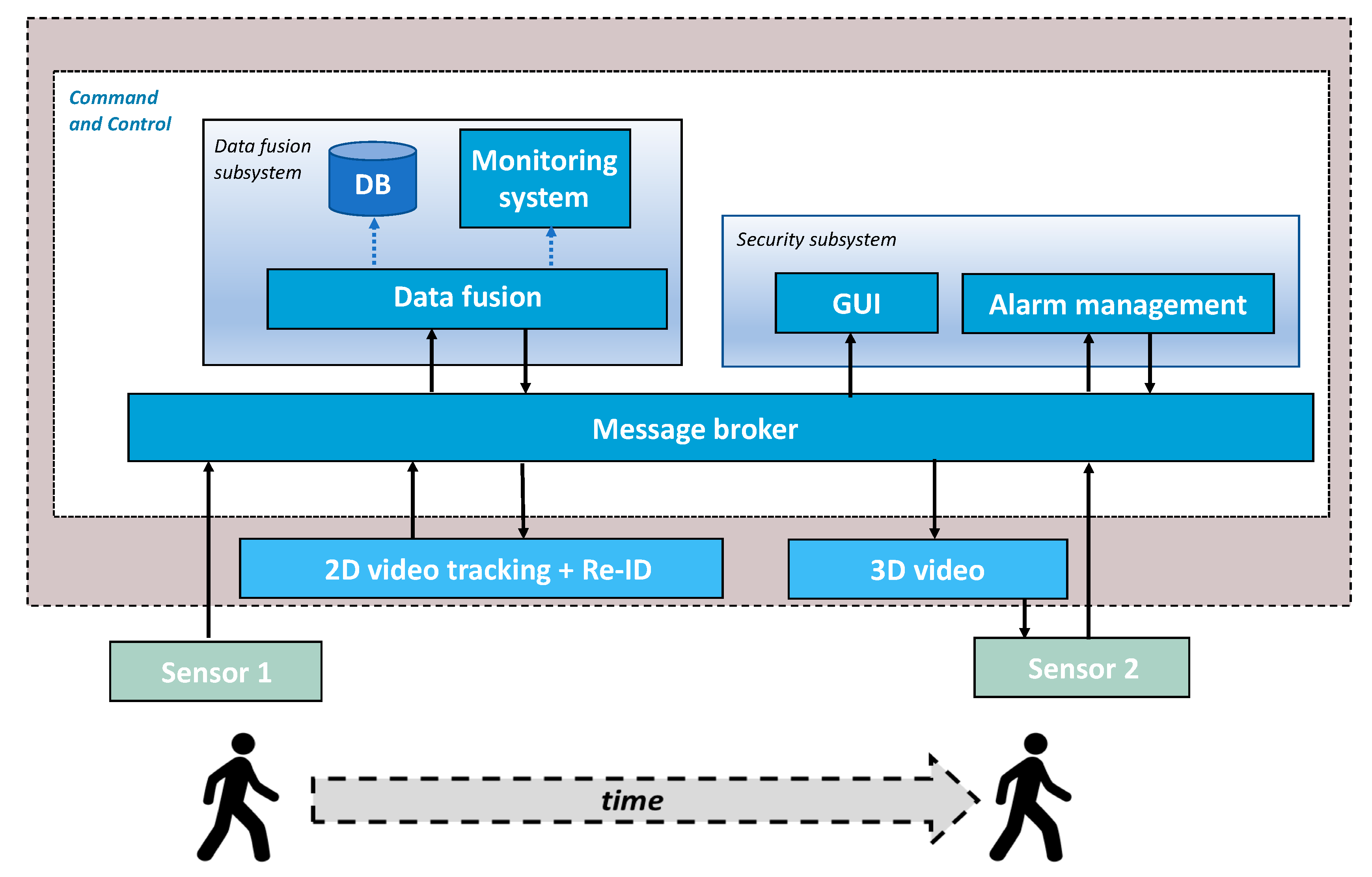
With reference to the architecture of Figure 2, the C&C is a distributed software component whose responsibilities are: data fusion for situational awareness, implemented by the Data fusion subsystem, smart alarm management, implemented by the Security subsystem, and communication management, implemented by the Message broker.
Data fusion. This is the core functionality of the Data fusion component, intended as a combination of data from multiple sources to improve the interpretation performances of the source data [27]. This component collects and processes data from the video and sensor-based systems to timely generate triggers and to deliver information related to suspect persons.
Monitoring and persistent storage of data. The data fusion is extended with functions for run time data visualization and storage. The former is accomplished by a Monitoring component providing data for Grafana dashboards [28]. These display events of interest of system performance at run time, captured by the Prometheus temporal database server [29]. Persistent storage of all the messages received and sent by the C&C is accomplished by the Instead DB implemented in MySQL [30]. Recorded data includes partial and complete sensor and video results, useful for system assessment and forensic activity.
Smart alarm management. This function, implemented by the Security subsystem component, concerns dispatching all the results of interest, including alerts, to several security sites, such as the agent smart glasses and a security room. The Security subsystem component includes a web application (GUI) devoted to displaying system results to the various clients that may be registered to this aim and an Alarm management component for dispatching alarms to the smart glasses subsystem and for receiving confirmation messages by the end users.
Communication management. This function is implemented by the Message broker that follows a publish–subscribe protocol to dispatch messages to all the technological components of the architecture.
A more detailed description of the implementation of the C&C components follows.

4.1. Data Fusion Subsystem

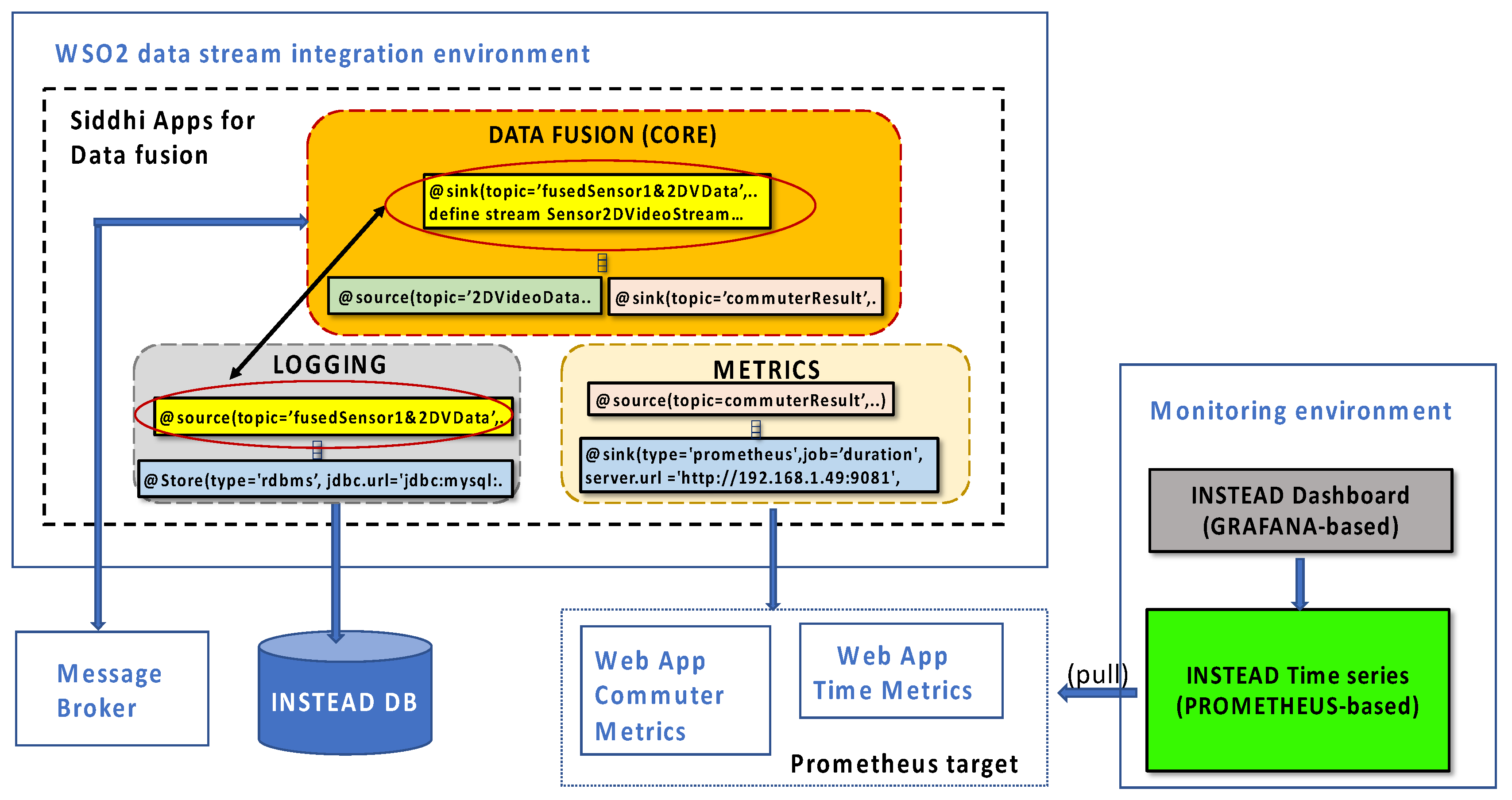
The software architecture of the Data fusion component is depicted in Figure 4. The Data fusion component has been developed as a collection of Siddhi Apps deployed and hosted by the WSO2 Streaming Integrator [31] technology. A Siddhi App is a processing unit of a declarative language, named Siddhi Streaming SQL, that provides complex event streams processing constructs and built-in communication interfaces with external systems interacting with the application. The set of Siddhi Apps implemented for the INSTEAD system are logically grouped into three modules: a core module, implementing the application logic, and two auxiliary modules for logging and metrics collection. The apps of the core module communicate with the Message broker, the apps for logging capture and compose the messages to be stored as records of the Instead DB, and the apps for metrics collection push raw application data, such as event counters and latency measurements, via HTTP to web pages, which are periodically scraped by a Prometheus server installation.
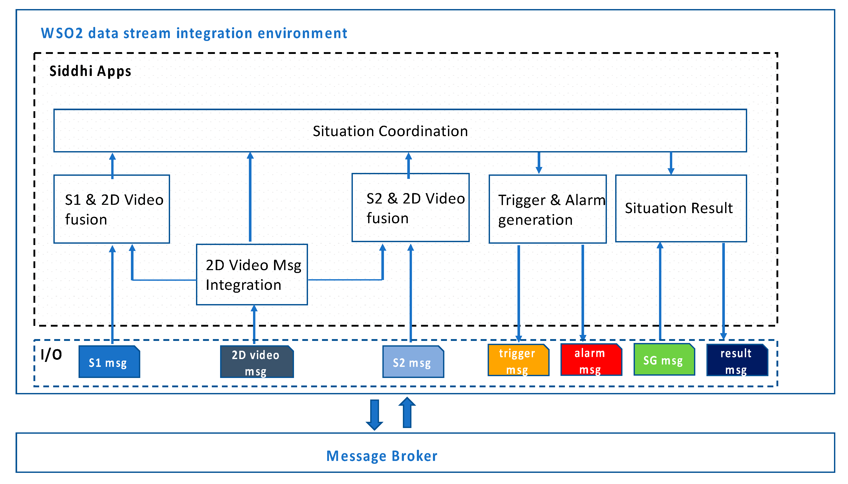
The Data fusion core apps are detailed in Figure 5. To meet the real time requirement, these apps run in different threads, each with a specific objective, and synchronize on shared data (i.e., common data streams shared by means of @source and @sink identifiers of Siddhi [31]). The 2D Video Msg Integration App listens to 2D Video-dimensional messages, provide other apps with relevant data for fusion, and correlates messages referring to the same commuter. For each sensor, a specific app is in charge at fusion with 2D Video data, to associate the sensor result with the image of the person. All the apps share an INSTEAD identifier of the commuter that is used by the Situation Coordination App to temporally align the data in correspondence of that commuter. Triggers and alarm messages are generated according to sensor results and event sequence rules to realize the flow described in Section 3.3. Situation result messages for the smart glasses and the GUI are built as soon as all the data is available or based on maximum waiting times. These can be empirically defined and adjusted during operation (without stopping the system), as it has been done during the Big City trials.
The modularity of the software architecture of the Data fusion component allows one to minimize the impact of changes on the external components to the corresponding apps handling their messages (e.g., incrementing/decreasing the number of detection lines of a commuter for the 2D Video) and/or on the rules for the triggers. Adding a new sensor would require adding a corresponding Sensor-Video fusion App, coded in a similar manner as the ones already implemented. The composition of the data for the situation result is based on timestamps.
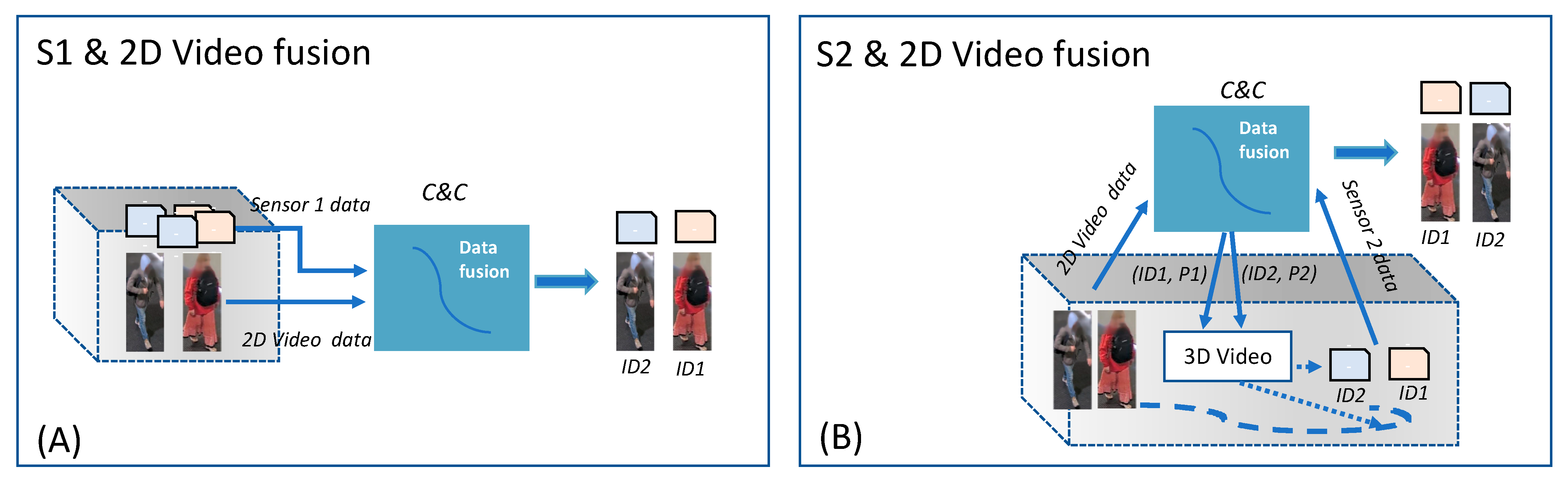
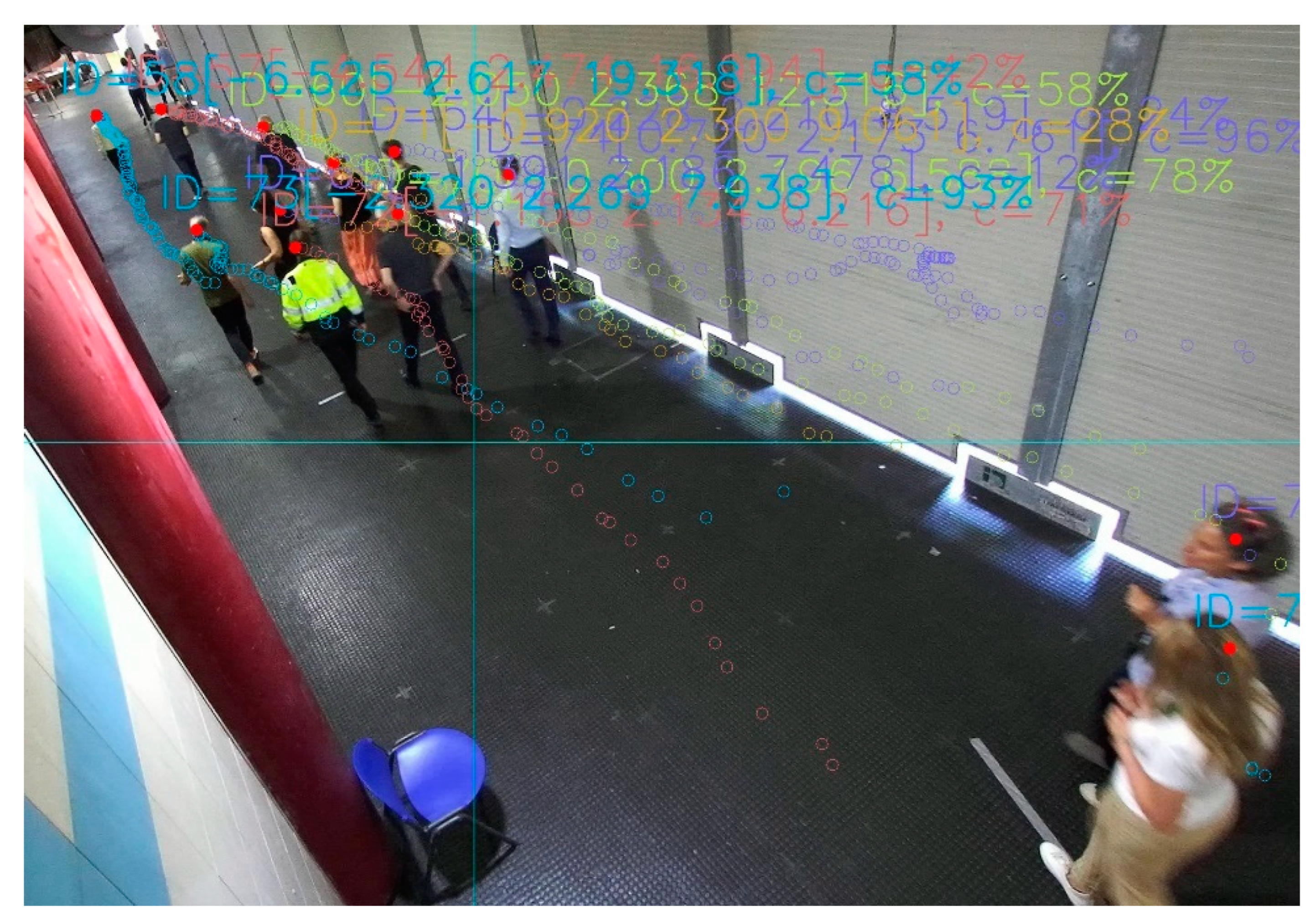
The 2D Video and sensor data fusion method does not assume an ordering for the receival of the messages from the two devices when referring to the same commuter. For the DEXTER system installation (see Figure 1), two types of video-sensor data fusion methods have been implemented, illustrated in Figure 6. The first method (A) is applicable for location-fixed sensors, such as MIC, that do not require assistance of a video camera for their operation. The second method (B) can be used for movable sensors, such as EXTRAS, that rely on an internal video camera to point on a person’s body before sensing activation. In this case, tracking hand-over between different video systems allows to maintain the association of the identifier of the person with the sensor results. The 2D Video-C&C- 3D Video tracking hand-over method is described in Section 4.3.3.
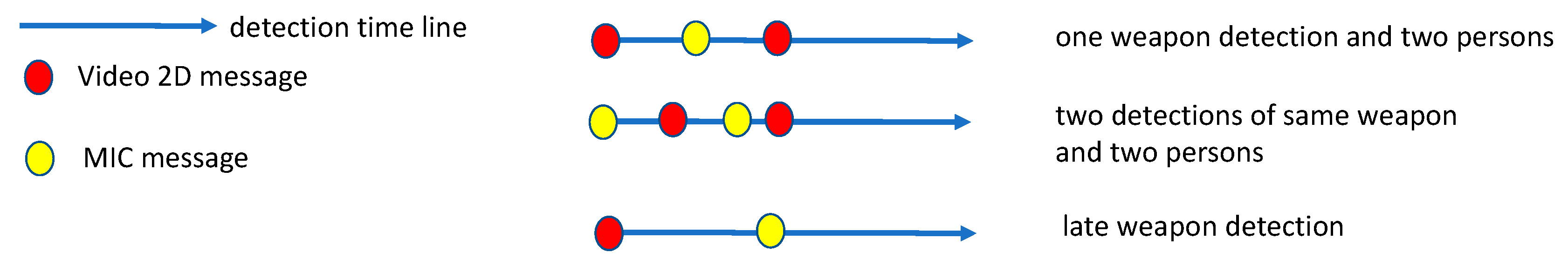
The first type of data fusion is challenging for the C&C in case of different commuters crossing the area with a short time distance among each other. The 2D Video and MIC data fusion has been based on the time of the two detections generated by the presence of a person in the common observation area, identified by a shared coordinate system. This time corresponds to the time when the 2D Video detects the person crossing the Init line, and the estimated time when the object identified by MIC before the line would be situated at the line. The last estimation was obtained based on the speed of the object/person while crossing the observed area. As MIC could send more than one message for the same object, to avoid false positives due to close commuters, time delays of about 2 (and 3) seconds between subsequent commuters have been experimented/established at the beginning of the trials.
Essentially, the data fusion method creates a queue of pairs (M, V), where M is a MIC message, and V is a 2D Video message, such that the distance of detection time contained in the M and V messages is less than 2 (or 3) s, and M may be received before or after V. Then, the pair with minimum time distance is chosen. Furthermore, to accommodate eventual non-negligible latency increases for receiving the messages from the external components (including the broker or delays due to the network), a time window of 2 min is applied for the observation of the incoming messages. Critical scenarios for this type of data fusion are described in Section 5.2.

4.2. Monitoring

The monitoring function is performed by means of Prometheus technology [29]. Prometheus is an open-source technology that can be interface with any system to supply monitoring and real time alerting functions. The monitoring function for the C&C is realized as a Prometheus job, i.e., an application-specific configuration for Prometheus identified by a name and HTTP target endpoints where application data are published, and which constitute the data sources for a Prometheus process. Prometheus allows one to implement metrics for a system as a combination of simple built-in metrics, such as count and gauge, on event data acquired from the monitored system and stored as time series. These time series can be queried by means of an internal expression language, useful to realize dashboards, for example by means of Grafana [28]. Dashboards for system performance, as well as displaying metrics, such as latency of functions and database accesses charts and statistics, are common and already exist as add-ons for many application server technologies, and domain-specific metrics can be useful to support ex post assessment, such as safety scenario analysis.
For the aims of both system performance and application-data analysis, various types of metrics have been put in place for the BCT deployed system. In particular, two groups of application-specific metrics have been implemented: “Time” and “Commuter” focused metrics. Time metrics compute the overall duration of the commuter detection in various scenarios of normal and threat cases. These have been used to compare the “virtual” duration of the trial runs with the real duration, i.e., the time employed by the system for a detection against the direct observation duration. Additionally, the time of MIC sensor–video data fusion operation has been computed to allow measuring the latency of the individual detections. This type of data at the BCT trials has been especially useful to recognize needs for component re-synchronization with the NTP server to adjust time accuracy, which is a necessary requirement for sensor–video data fusion.
Commuter metrics allow one to summarize events of interest referring to the detection results, as shown in Figure 7. This dashboard is used to obtain an automatic summary of the trials and verification against the planned scenarios.
In an ex-post analysis, by combining these metrics on the same timeline, it is possible to elaborate time profiles of crowds traversing the monitored area that can be used for a better tuning and for future enhancements of the system.

4.3. Components Communication

The Message broker is the technological mean through which all the components send and receive application-specific data delivered with a timestamp synchronized with respect to the time of a common NTP server local to the network.
Two aspects are relevant for flexible integration: the definition of a message exchange protocol and its structure, which allow one to easily integrate sensors and security applications in the architecture, and a method for an accurate and efficient video tracking hand-over from two different types of video systems.

4.3.1. Communication Model

The publish–subscribe model has been adopted for communication of these highly decoupled components and to increase the flexibility of the architecture. The components may register as publisher or subscriber of some message type at run time, hence avoiding a system set up phase. Thus, the broker is a central element for integration.
The message flow relies on topics, which are strings indicating the scope (e.g., the system name), the type of the message, and the result type. More specifically, for the DEXTER deployment at Anagnina, the topics are structured as:
  • dexter/sensorResult/[resultType], where [resultType] corresponds to: MIC and EXTRAS detection for the sensors; to 2D Video result, which is further specified with the region of detection of the commuter, e.g., dexter/sensorResult/Video2D/Init; and to the C&C component triggers following MIC and EXTRAS data fusion e.g., dexter/sensorResult/MICSuspect and dexter/sensorResult/alarm;
  • dexter/[state], where [state] is any state of the C&C built situation that may be of interest to display on user interfaces, for example of the security room or for system demonstration, e.g., dexter/threat and dexter/normal are used to publish the final result for a commuter, positive and negative respectively, aggregating the sensor detections and 2D Video images of each commuter;
  • dexter/alarmResult, published by the Alarm management system client to notify the C&C and other security systems whether the commuter in the image on the smart glasses has been recognized by the guard in the real environment.
As shown in Figure 2, Sensor 1 and Sensor 2 are the only publishers of detection results, whereas the INSTEAD components are configured as follows.
The 2D Video publishes messages from each camera containing label and image of any intercepted commuter crossing the pre-defined lines. Moreover, the 2D Video may subscribe to receiving Sensor 1 messages to later use them to support prioritize tracking and reidentification of suspect commuters. However, this feature has not been used in the experimented system.
The C&C Data fusion component subscribes to messages by all the components. Furthermore, it publishes trigger messages and final state results.
The 3D Video component subscribes to receiving tracking hand-over trigger messages and directly communicates the commuter location data to Sensor 2.
The Security client subscribes to alarm and other result information messages and publishes the result on the recognition of the threat commuter.

4.3.2. Component Interfaces

To best accomplish interoperability and security requirements, the messages are formatted in JSON, and the MQTT (MQ Telemetry Transport) [32] application-layer protocol is used over a local network linking the various servers. The HiveMQ [33] broker has been used for the experimentation, which implements MQTT v5, an OASIS standard.
A sensor generic message format has been defined, illustrated in Figure 8, where the semantics of the fields are as follows:
  • “sensorId” is a string identifying the specific sensor-based system of the deployment.
  • “detectionId” is a string representing a unique identifier associated with the object of the detection (i.e., a weapon by MIC or a commuter by 2D Video) and assigned by the specific sensor-based system. In case of more instances of the same detection (e.g., video re-identification and tracking), this detectionId has to be the same.
  • “insteadDetectionId” is a string generated by the C&C in correspondence with a commuter, and it is used to correlate sensor messages.
  • “detectionTime” is a string representing the absolute time of the result of the sensor observation, and it follows the ISO 8601 combined date and time format. The Universal Time Coordinates (UTC) can be chosen as a reference time, which is provided by an NTP server of the private network.
  • “value” is an array of json property objects specific for the sensor/component, containing one or more measurement results with confidence level (number between 0 and 1). The threshold value is a configurable parameter by the sensors, that is defined based on the overall system performance. The threshold value used by the sensor at the time when the measurement is performed is transmitted to the C&C for ex post analysis.
  • “coordinates” is an array of float, e.g., [x, y, z], where [x, y] correspond to a point in the corridor, and z is the minimum height of the recognized object, if any. The explicit purpose of these world coordinates is to share the location of a person or object between the external sensors and the INSTEAD internal components. In particular, the C&C can use space–distance information to implement the data fusion.
  • “dataURL” is a reference to the recorded result by the individual sensor/component system, for example following REST API convention, from where detailed result data may be retrieved.
Examples of JSON messages generated by MIC and 2D Video during the trials are displayed in Figure 9. These messages, received by the C&C, lead to a data fusion based on the small difference on the detectionTime parameter of the two messages. The MIC message was actually received by the C&C about 550 milliseconds before the 2D Video message, and the (detection) time estimation of MIC when the object would have been positioned at the specified coordinates (about the 2D Video Init detection line) was quite accurate.
It should be noted that the “value” parameter may contain simple or structured objects, as in the case of the 2D Video. Furthermore, the same JSON structure, or an extended one, is used by the C&C to instantiate trigger and alarm messages for the other components. Following what was proposed in [34], the data fusion may be interpreted as a virtual sensor observing complex or aggregated properties. In this case, the “value” parameter would specify the list of measurement objects of interest. In the example of Figure 9, the data fusion generates a (virtual) sensor result message with a not-null insteadDetectionId, the detectionTime as the time of the data fusion, and as value the array of values from the two source messages. Such data fusion message is useful for the monitoring and security interfaces.

4.3.3. Video Tracking Hand Over

The 3D Video is triggered by a JSON message extending the structure of Figure 8, which is sent by the C&C incorporating the 2D Video JSON message with position data of the commuter and eventually a prioritization flag in case of a positive message already received from Sensor 1. This message is sent when the commuter is approaching Sensor 2. The 3D Video completes the hand-over procedure both in temporal and spatial space in three main steps as follows (Figure 10). First, it finds all the tracks having samples within ±1 s to the timestamp indicated in the trigger message and are without a priori successful hand-over status. Secondly, it selects the tracks in the output set of the previous step which are within the radius of 0.75 m to the real-world point embedded in the trigger message. This step includes coordinates mapping from the three-dimensional space internal to the three-dimensional sensor of the real-world counterpart. Finally, it assigns a successful hand-over match to the track (if any), which is closest to the location specified in the trigger message.
If the hand-over fails in the very first attempt, the 3D Video system re-tries in 200 ms cycles with the very latest available track buffer contents up to four times in total. This improves handover reliability and robustness in occluded highly crowded scenes.
With respect to persons having a successful hand-over status, the 3D Video computes a location prediction one second forward in future. It computes a prediction per a track as new samples arrive track-specifically and deploys a machine learning data model based on a recurrent neural network (RNN) [35] that is capable of covering not just straight tracks, but also curved and wobbling ones at variable walking speeds. An RNN-based approach has been selected for the prediction, since it has been acknowledged as a feasible technical baseline for accurate motion trajectory prediction in published academic works, such as [36].
More in detail, the RNN Data Model consists of a neural network structure, depicted in Figure 11, which has an input LSTM layer with 256 neurons followed by a fully connected linear activation function layer of two neurons. The input data feed comprises two inputs to the model. The first input contains historical up-to-date track data for the past second, which is pre-processed in three steps: interpolation to a fixed 10 Hz sample rate, calculation of the first-order derivatives of consecutive X and Y coordinates, and finally normalization of the derivatives to the range [0, +1] considering the min-max tracking range of the three-dimensional sensor. The second input to the data model consists of normalized derivatives of the very first and last X-Y coordinates in the current track history buffer. The data model output is a normalized X-Y offset to the last known X-Y coordinate point. The data model has been trained with three-dimensional sensor track data (about 5000 unique tracks) collected in the real-life environment at the Anagnina station in November 2021. The data model training phase has included data augmentation by rotating the input tracks at random angles in the X-Y plane. The normalized coordinate derivatives with data augmentation have been the key approaches enabling the resulting data model to achieve improved robustness and generalization to various target deployment environments.

4.4. Security Subsystem

The Security subsystem is composed of: a Graphical UserInterface (GUI) and a smart Alarm management system.
The GUI has been implemented as a web application connected to the message broker via web socket, so it allows final users to visualize the results on a web browser from different devices. The presentation layer is based on [37], and it allows every client to subscribe to both normal and threat commuter overall results. The GUI has been used to support the BCT evaluation of the DEXTER system.
The Alarm management system is a commercial system of in-door location intelligence finalized to the coordination of security agents, wearing smart glasses, who react to alarms generated by the C&C. In this case, a JSON message compliant with the structure in Figure 8, and with details of the threat commuter (e.g., 2D Video re-id data and sensor results), is published by the C&C to the Message broker. The Alarm management system also incorporates a MQTT broker to handle both the internal communication of the server part of the application with the various pairs of smart glasses devices connected to the system and the communication with the INSTEAD Message broker.
The MQTT broker of the Alarm management system filters the alarm messages published by the C&C to the INSTEAD Message broker and propagates the data to the smart glasses devices worn by the security guards. They are able to identify the person through the image supplied by the system over imposed on their field of view and may react when that person is still near the monitored corridor. A confirmation message can be published to the local MQTT broker by an interaction of a guard with the smart device, which is automatically shared with the INSTEAD system.

5. Experiments and Results

The first release of the INSTEAD system, without the sensors and the alarm management system, was deployed at Anagnina during October 2021. This early installation allowed for tuning the deep learning methods used by the video components with real local data and for testing the system also in a non-controlled environment. The modular architecture of the C&C facilitates both upgrading the existing software and extending the architecture with new components without affecting the previous behavior. The testing period lasted until the BCT, which started in May 2022, when the MIC, EXTRAS, and the Alarm management system were integrated, and the controlled environment was introduced. The corridor was protected by barriers to allow entrance and walk only to the project participants and to pre-identified volunteers.
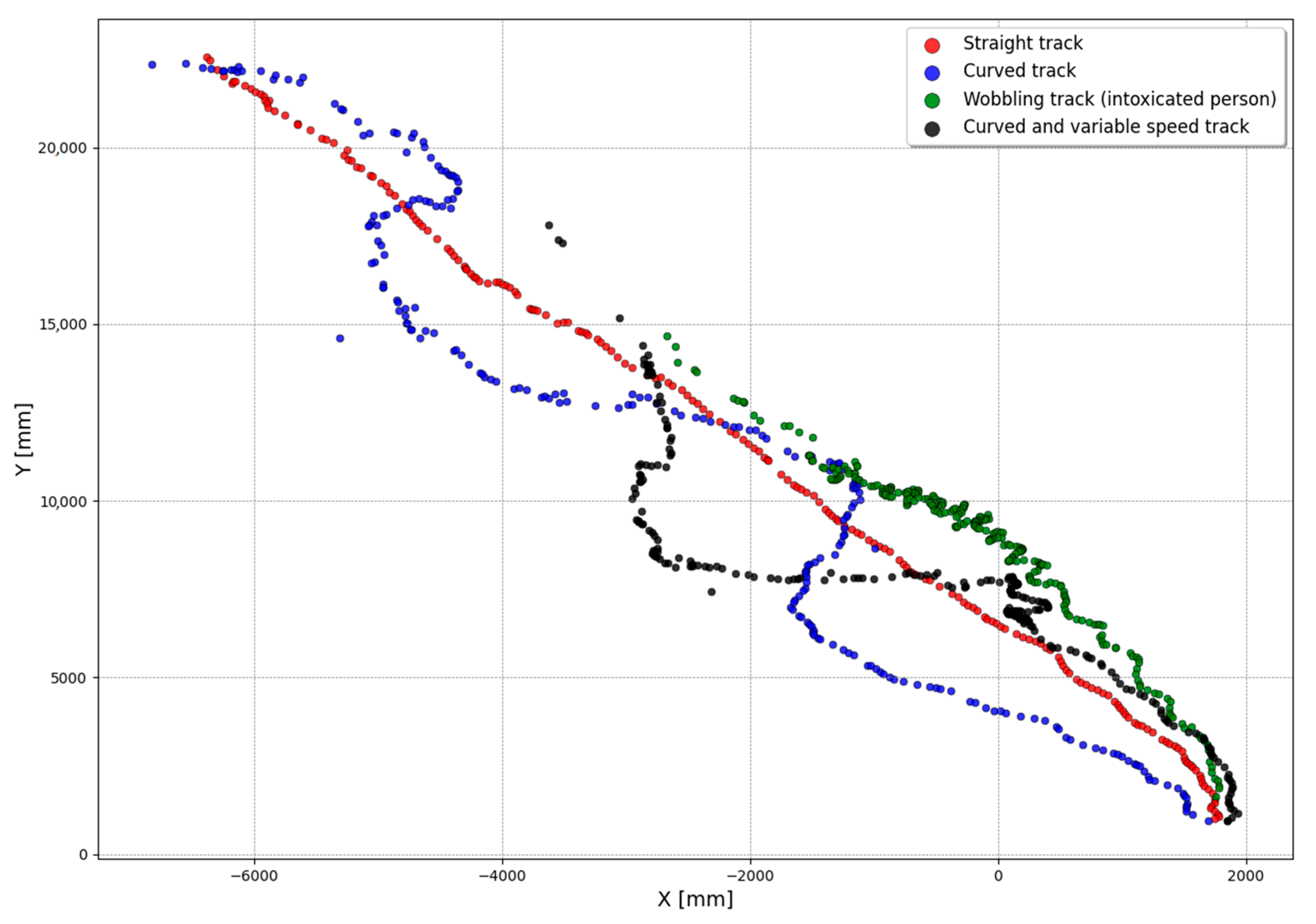
The BCT test runs consisted of tracks, which mimic real-world human walking at a metro station, including various speeds, stops, curved, and wobbling gait patterns. Figure 12 depicts real-life examples on these cases as captured during the BCT experiments by the 3D Video sensor and illustrated in X–Y plane in real-world coordinates. During the BCT test runs, the average walking speed was 0.8 m/s and 75% of the tracks had their variation within the ±0.3 m/s range.
Data captured at Anagnina using the 3D Video system on 1–19 April 2022 demonstrates that BCT test runs have had commuter speeds close enough to real-life conditions.
In the following, the INSTEAD results on the BCT trials are briefly presented. The system validation was performed in real time by supervisors, including experts appointed by NATO who had prepared the trials, and they were verified after an accurate ex post analysis of the system logs. In particular, the INSTEAD system accuracy and that of the INSTEAD–sensor integration have been evaluated.
The INSTEAD system accuracy has been computed as the number of correctly detected commuters, i.e., in this case, correctly (re)identified by the 2D Video at init, reid, and exit line and correctly tracked by 3D Video over the number of commuters.
The INSTEAD–sensor integration accuracy has been computed as the number of false positive and false negative threat results, considering the messages sent by the sensors, over the number of correctly detected commuters. The details of the system assessment are discussed in [7].
Here, the focus is on the analysis of the results of the two data-fusion methods described in Section 4.1 and on lessons learned for further improvement. Additional performance results of INSTEAD when operated in the same environment without the scenario constraints imposed by the two sensors are described in this paper.

5.1. BCT Results of INSTEAD in the Official NATO Scenarios

The BCT consisted of 287 runs for a total of 586 commuters following pre-defined scenarios defined by NATO, which had been kept confidential until the actual performance. Each run involved from 1 to 4 concurrent commuters consisting of volunteers wearing colored jackets, arranged so to have different colors within each group.
The total accuracy of the INSTEAD pipeline: 2D Video-C&C-3D Video is 97.6%, whereas the relative accuracy of each component is 98.5%, 99.5%, and 99.7% respectively. These results have been discussed in [7], whereas a qualitative evaluation of the data fusion methods follows.

5.2. Data Fusion Specific Results Analysis and Lessons Learnt

The INSTEAD—MIC data fusion success at the BCT is 93.4%, as described in [7]. Essentially, the time-based data fusion method described in Figure 6A has been challenged by: (1) the accuracy of the detection time of the MIC and 2D Video messages, i.e., the time when the object/person is at the init line (estimated in the case of MIC); (2) the fact that the relation of the messages 2D Video-MIC is one-to-many, i.e., one 2D Video message referring to a person may be related with more than one MIC message referring to the same weapon (possibly carried by that person); and (3) the time difference between the MIC detection and the 2D Video detection that, if too large, could lead to a missed data fusion.
Thus, the risks of failures illustrated by the scenarios in Figure 13 should be considered when implementing such method. The first case, related to (1), shows the situation of a MIC message with detection time between those of two different persons detected by the 2D Video. In this case, the data fusion may result in an incorrect message association. The second case, related to (2), shows the situation when two detection messages of the same weapon by the sensor provide quite different (estimated) detection times so that, in case two persons are detected in between by the 2D Video, and the data fusion method may not uniquely identify the situation (e.g., two concurrent threats, carrying the same type of weapon, or just one threat detected by MIC more than once with increasing confidence level). The third case, related to (3), shows the situation when the detection times of the weapon and of the person is much different.
Some control strategies were adopted during the BCT official trials to mitigate the occurrence of the scenarios above for the C&C. A minimum frequency between subsequent commuters to avoid MIC detections overlapping with 2D Video persons labelling was experimented during the runs and this resulted in about 2–3 s. This time was considered realistic for the given door-based deployment of MIC (Figure 1). Furthermore, accurate time synchronization of the servers hosting the individual components with the NTP server is fundamental to ensure that the detection time delivered by the two components inside the messages are coherent in this respect. Time synchronization was constantly monitored and occasionally manually forced during the trials when significant differences were observed. Network traffic is another influencing factor that might have caused late delivery of messages due to various additional clients connected to the broker for debugging purpose.
Based on this experience, lessons learned for future work include the following.
  • Including and/or deriving more information from the field in the data fusion method while maintaing at least the accuracy demonstrated at the BCT.
  • Improving the time synchronization of the system components.
  • Activate a network monitoring activity to check connections and avoid unnecessary traffic.
The EXTRAS—INSTEAD data fusion success at the BCT is 77.58%, as described in [7]. For this type of data fusion (identity-based, see Figure 6B), the C&C relies on a correct video tracking hand-over from the INSTEAD 3D Video to the video mounted on the sensor. However, in theory, a risk of missed data fusion by the C&C might be due to a sensor detection of a commuter not previously tracked. This problem has occurred in a few runs at the BCT for groups of commuters not clearly identifiable at the init line by the 2D Video system. As demonstrated by additional experiments reported in the Section 5.3, this problem of missed 2D Video tracks might depend on occlusion or the disposition of the MIC panels before the init line (see also [7] for details) and so it could be faced by considering the following three possible enhancements of the software.
  • Implementing deployment-based variants of the method, according to the disposition of MIC and 2D Video devices in the environment.
  • Lightening the data-fusion constrains on the presence of these tracks towards a more flexible handling of scenarios with missed data.
  • Improving the 2D Video processing to avoid occlusion in crowded environments (see ‘group mode’ in [23] for details).

5.3. Experimental Results on Offhand Scenarios

To assess the scalability of the INSTEAD system, additional runs with an increasing number of concurrent commuters were performed during the BCT days and without the restrictions on paths and speed required by the two sensors. In this case, the system was running as usual while MIC and EXTRAS sensors were simply not operational. In particular, the volunteer commuters were dressed normally and, for each run, they started their walk at the init line and ended at the exit line.
Table 1 presents the results of these group runs, in temporal order of execution in different days, where the commuters were successfully detected by the C&C based on the messages from the 2D Video. In particular, the data refer to the time employed by groups of different sizes to traverse the video monitored area, accessing at the same time (crossing the init line with a few seconds of difference). These experiments are useful to demonstrate the scalability of the C&C software in processing concurrent messages and meet the real time requirement. By a comparison with the average results of an official BCT run, where the duration was influenced by the time constraints of the sensors for detection and processing, higher speed and larger variations within groups were also experimented.
The first three runs were executed during the BCT experimental period, while the fourth and fifth were executed during the subsequent two days where the system was presented and demonstrated in front of, and involving, various types of stakeholders such as project collaborators and guests.
The real time performance is demonstrated by a successful video tracking hand-over to the 3D Video (Figure 14), triggered by the C&C. In the BCT test runs, the 3D Video has achieved 100% success rate in tracking. Furthermore, the BCT results show that the 3D Video is capable to track and compute the hand-over and predictions for at least 25 concurrent persons. The 3D Video capacity limit comes from the raw computational performance of the deployed computation hardware platform.

6. Discussion

The deployment in an open and real environment for pre-integration testing and the large-scale experimentation of the BCT have been a great opportunity to evaluate the presented architecture against the functional requirements and also some non-functional aspects. An account of aspects such as performance, flexibility, scalability, security, usability, and potentials for re-use follows.
“Performance”. This aspect has been evaluated through: accuracy results, i.e., the number of successful detections over the number of runs, which have been reported in Section 5 and, for the official BCT runs, have been detailed in [7]; and latency, i.e., the time delay due to processing and communication. Communication latency depends on the network load and on the performance of the MQTT broker. As the system should be deployed in a private dedicated network and the message payload, described in Section 4.3, which is negligible in this respect, communication might be delayed when increasing the number of concurrent commuters as the number of exchanged messages increases. However, the experiments discussed in Section 5 represent realistic numbers of concurrent commuters for the considered environment. Furthermore, latency due to communication and data processing by the C&C, monitored as described in Section 4.2, has resulted in being more than adequate to meet the real-time requirement of detections, which has been extensively validated by official project evaluators and by the end users during the demonstration.
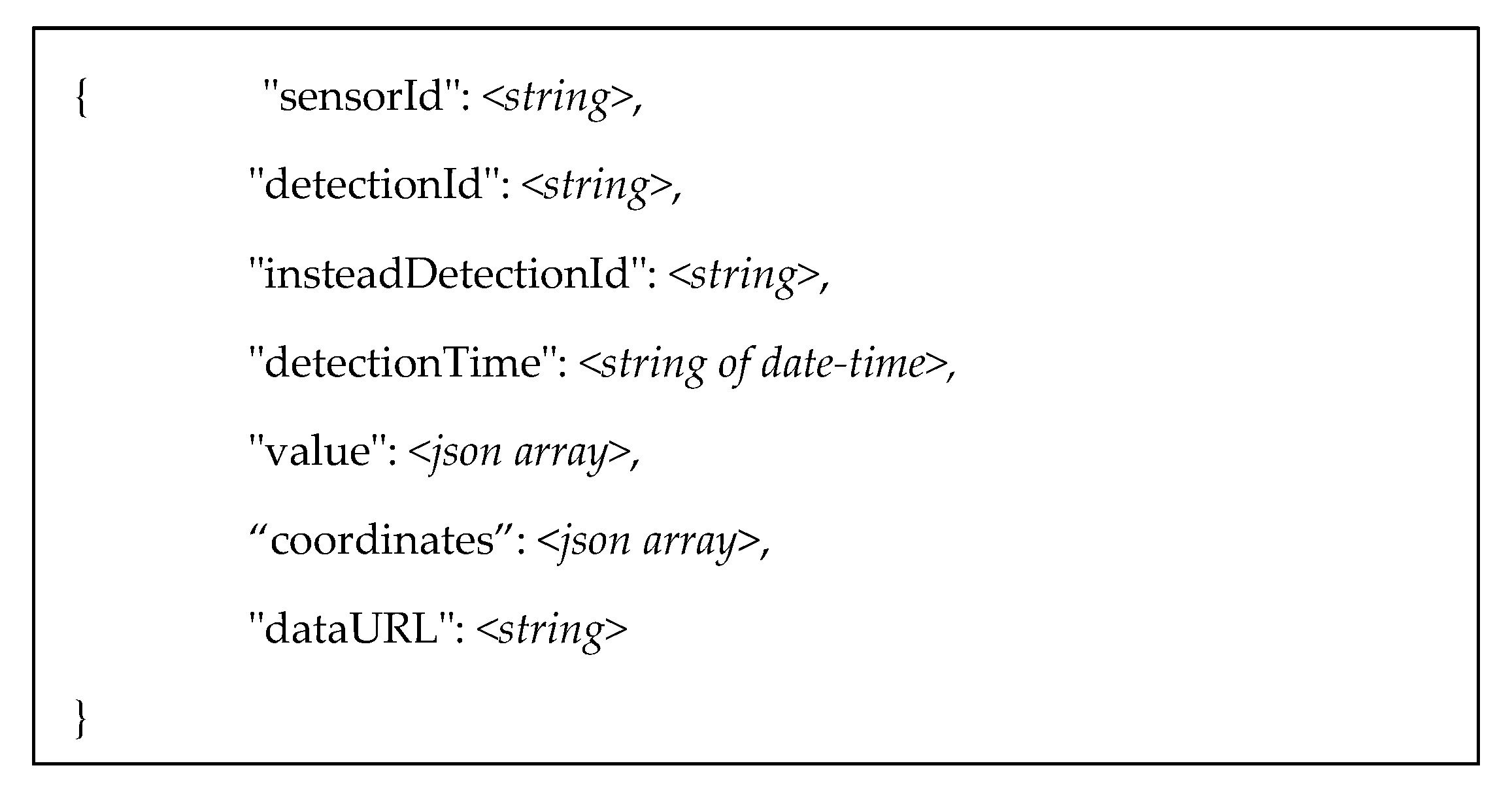
“Flexibility”. This aspect is related with the capability of the system to adapt to variability of external conditions without undergo significant structural modifications, including extensibility with new features. The experiments have demonstrated robustness with respect to different types of external scenarios: variability of the commuters (group size, physical characteristics and dresses) and paths; and variability of light conditions in the same environment. While these mainly affect the functioning of the two video systems, assuming correctness of their messages, the flexibility of the C&C concerns: continuity of operation (e.g., commuter detection and tracking) in case of unavailability of the sensors and/or their disconnections and reconnections at run time; extensibility of the transmitted data by the components with further information, e.g., more images or data related to the detections, thanks to the data structure described in Section 4.3.2; and extensibility with new sensor systems by using the same message structure and communication model and with limited development work, as described in Section 4.1.
“Scalability”. This aspect refers to the capability of the system to correctly handle increasing number of concurrent messages that, in this case, may be generated by the commuters and/or when connecting additional components to the system. For the first aspect, some experiments in that direction have been performed, as discussed in Section 5.3, but more stress tests should be performed, especially when considering corridors of higher capacity of concurrent commuters. With reference to the number of connected components, the most affected component of the C&C architecture is the MQTT broker, which is a third-party component. The broker used in the experimentation, HiveMQ, has turned suitable to handle the connections of the components of the architecture and of the various user interfaces and clients connected to the system for debugging purpose, which did not affect the presented results.
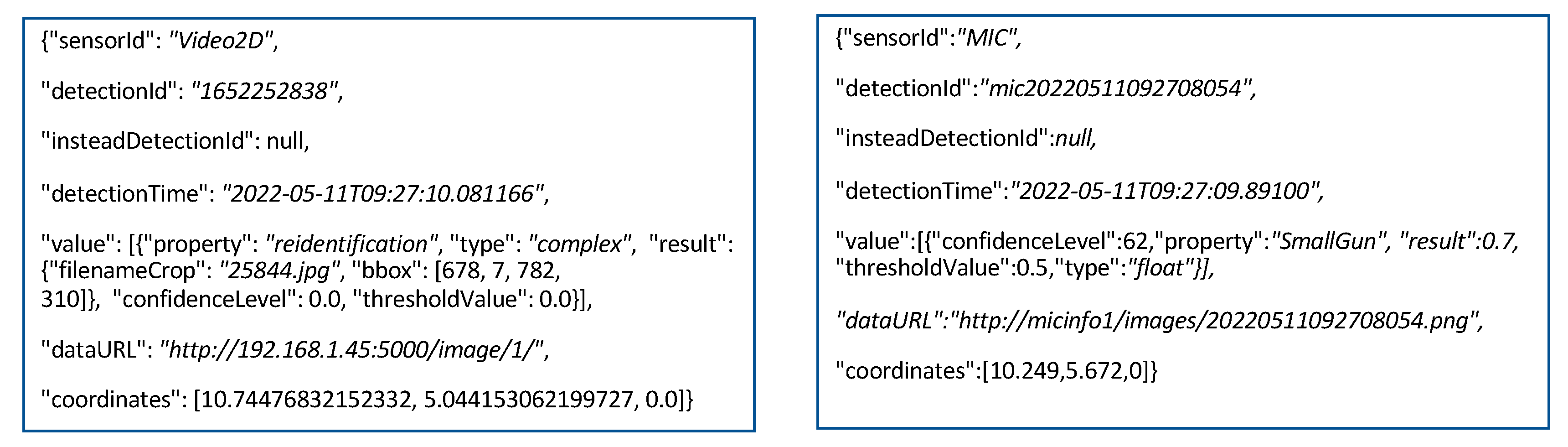
“Security”. This aspect refers to protection of sensitive data and of the system from unauthorized use. For the aim of privacy protection, the images/data generated by the video systems and by the sensors are kept at the source servers, as only the data urls are supplied in the messages. Indeed, download of such data by the C&C only happens when there is need to display images on the smart glasses (and/or on a security GUI). Moreover, the images of the commuters are anonymized by blurring the upper (approximately 20%) part of the detection, which usually contains the face, and the 3D Video system captures only three-dimensional coordinates of the tracked persons (i.e., no video or image snapshots). The secure communication is natively supported by MQTT, such as client authentication and encrypted communication. The extent to which such security measures may impact on the system performance will be assessed as future work.
“Usability”. The architecture supports processing and packaging of collected multi-source data into a single product of actionable information delivered to the operator. Moreover, as an innovative feature of the system is the support to security guards on field by means of smart glasses, usability of such technology is a key aspect which has been directly and positively evaluated at the BCT by the Italian police.
“Modularity”. This is the main feature of the architecture that allows fusion of disparate technologies into a single modular ensemble, which favor reuse. Furthermore, utilizing a modular “OR” type interface for threat detection is advantageous in data aggregation since it permits the application to adapt flexibly to more scenarios, including, but not limited to, for example, when one sensing opportunity is not present or possible.
“Reuse”. Such an aspect has to be discussed for each component of the system. The C&C has been designed to be: independent from specific sensor and video systems, as the messages provide final detections results, and data fusion only refers to attribution of an object to a person and to combination of the sensor results for alarm triggering; independent from geometrical/environmental characteristics of the place where devices are deployed, the only constraint is that the flux needs to be one-directional. The modularity of the internal architecture of the C&C allows one to re-use the data fusion component with different tools. In this respect, the MQTT broker, the Security client (including the smart alarm management system), and the Monitoring system could each be replaced by a different tool. The two video systems are also reusable. The 2D Video re-identification component can be installed in new environments due to rapid re-training [23]. This can support tracking and fusion in a region even where the field of views of the cameras are not overlapping. In addition to crowd management solutions, the 3D Video monitoring methods can be utilized in other industrial use cases, including, but not limited to, for example, human mobility and task monitoring in industrial and construction domains providing task monitoring and improved work safety. In addition, location information originating from other sensors, such as, for example, millimeter radar and UWB, which can be fused for obtaining more accurate location and person activity information.

7. Conclusions

The paper described the architecture of a command-and-control system supported by two intelligent video systems for multi-sensor fusion aiming at automatic threat detection in crowded spaces. When deployed at different locations near or inside a critical infrastructure, such as an airport or a metro station, the system itself can be a building block of a wider threat detection system for infrastructure protection. The main features of the system, compared to previous works, are the modularity of the architecture, which allows to re-use all or some of the components in different sensor-based deployments, and the integration of smart glasses to deliver the results to the security guards and support them reacting on the field.
The validity of the architecture has been demonstrated when integrated with two different sensor systems in a large-scale experimentation at a metro station in Roma. Various non-functional aspects of the architecture have been discussed, which also use experimental results. A more accurate assessment of the scalability of the system for high-density crowds and the integration of the command-and-control system with an existing security system of a critical infrastructure are future directions of the work.
Technological upgrades and use of redundant components to improve the system fault tolerance can be foreseen as future enhancements. The current equipment consists of common-of-the-shelf (COTS) hardware with standardized interfaces, so it is possible to replace the devices with new models. Furthermore, technology enhancement of the command and control with commercial tools, especially to empower the communication and monitoring subsystems, and to better manage security, should be foreseen to achieve higher levels of quality of service, such as when scaling up to more installations of INSTEAD, as illustrated in Section 3.

Author Contributions

Conceptualization, M.L.V., A.D.N., H.B., A.v.R., P.R., J.P., S.T., M.G., C.S. and L.D.D.; Methodology, M.L.V., A.D.N., H.B., A.v.R., P.R., J.P. and S.T. and M.G.; Software, M.L.V., A.v.R. and P.R.; Data curation, M.L.V., A.v.R. and P.R.; Supervision, H.B., S.T., C.S. and L.D.D.; Validation, C.S. and L.D.D.; Writing—original draft, M.L.V.; Writing—review and editing, M.L.V., A.D.N., H.B., A.v.R., P.R., J.P., S.T., M.G., C.S. and L.D.D. All authors have read and agreed to the published version of the manuscript.

Funding

The INSTEAD (“INtegrated System for Threats EArly Detection”) project has received funding in the DEXTER (Detection of EXplosives and firearms to counter TERrorism) program from NATO Science for Peace and Security (SPS) under grant agreement number G5605 and G5969.

Informed Consent Statement

Informed consent was obtained from all subjects involved in the study.

Data Availability Statement

The data presented in this study are not publicly available due to project restrictions.

Conflicts of Interest

The authors declare no conflict of interest.

References

  1. Lazic, V.; Palucci, A.; De Dominicis, L.; Nuvoli, M.; Pistilli, M.; Menicucci, I.; Colao, F.; Almaviva, S. Integrated laser sensor (ILS) for remote surface analysis: Application for detecting explosives in fingerprints. Sensors 2019, 19, 4269. [Google Scholar] [CrossRef] [PubMed] [Green Version]
  2. Deiana, D.; Hanckmann, P. Multi-Sensor Fusion Applied to the Detection of Person-Borne Improvised Explosive Devices (PB-IEDs). In Proceedings of the 2019 PhotonIcs & Electromagnetics Research Symposium—Spring (PIERS-Spring), Rome, Italy, 17–20 June 2019; pp. 3978–3982. [Google Scholar]
  3. Al-Sa’D, M.; Kiranyaz, S.; Ahmad, I.; Sundell, C.; Vakkuri, M.; Gabbouj, M. A Social Distance Estimation and Crowd Monitoring System for Surveillance Cameras. Sensors 2022, 22, 418. [Google Scholar] [CrossRef] [PubMed]
  4. Bouma, H.; Schutte, K.; Hove, J.-M.T. Flexible human-definable automatic behavior analysis for suspicious activity detection in surveillance cameras to protect critical infrastructures. Proc. SPIE 2018, 10802, 192–203. [Google Scholar]
  5. Whaiduzzaman, M.; Barros, A.; Chanda, M.; Barman, S.; Sultana, T.; Rahman, M.S.; Roy, S.; Fidge, C. A Review of Emerging Technologies for IoT-Based Smart Cities. Sensors 2022, 22, 9271. [Google Scholar] [CrossRef] [PubMed]
  6. NATO-SPS. NATO Science for Peace and Security (SPS) Programme; Annual Report; NATO: Brussels, Belgium, 2018; Available online: https://www.nato.int/nato_static_fl2014/assets/pdf/2020/2/pdf/200221_NATO_SPS_AnnualReport2018.pdf (accessed on 30 November 2022).
  7. Bouma, H.; Villani, M.L.; van Rooijen, A.; Räsänen, P.; Peltola, J.; Toivonen, S.; De Nicola, A.; Guarneri, M.; Stifini, C.; De Dominicis, L. An Integrated Fusion Engine for Early Threat Detection Demonstrated in Public-Space Trials. Sensors 2023, 23, 440. [Google Scholar] [CrossRef]
  8. De Dominicis, L.; Bouma, H.; Toivonen, S.; Stifini, C.; Villani, M.L.; De Nicola, A.; van Rooijen, A.; Baan, J.; Peltola, J.; Lamsa, A.; et al. Video-based fusion of multiple detectors to counter terrorism. Proc. SPIE 2021, 11869, 75–85. [Google Scholar]
  9. Papčo, M.; Rodríguez-Martínez, I.; Fumanal-Idocin, J.; Altalhi, A.H.; Bustince, H. A fusion method for multi-valued data. Inf. Fusion 2021, 71, 1–10. [Google Scholar] [CrossRef]
  10. Zhang, Y.; Jiang, C.; Yue, B.; Wan, J.; Guizani, M. Information fusion for edge intelligence: A survey. Inf. Fusion 2022, 81, 171–186. [Google Scholar] [CrossRef]
  11. Zhang, P.; Li, T.; Wang, G.; Luo, C.; Chen, H.; Zhang, J.; Wang, D.; Yu, Z. Multi-source information fusion based on rough set theory: A review. Inf. Fusion 2021, 68, 85–117. [Google Scholar] [CrossRef]
  12. Yang, J.; Yang, L.T.; Wang, H.; Gao, Y.; Zhao, Y.; Xie, X.; Lu, Y. Representation learning for knowledge fusion and reasoning in Cyber–Physical–Social Systems: Survey and perspectives. Inf. Fusion 2023, 90, 59–73. [Google Scholar] [CrossRef]
  13. Qi, J.; Yang, P.; Newcombe, L.; Peng, X.; Yang, Y.; Zhao, Z. An overview of data fusion techniques for Internet of Things enabled physical activity recognition and measure. Inf. Fusion 2020, 55, 269–280. [Google Scholar] [CrossRef]
  14. Lau, B.P.L.; Marakkalage, S.H.; Zhou, Y.; Hassan, N.U.; Yuen, C.; Zhang, M.; Tan, U.-X. A survey of data fusion in smart city applications. Inf. Fusion 2019, 52, 357–374. [Google Scholar] [CrossRef]
  15. Li, Y.; Yang, G.; Su, Z.; Li, S.; Wang, Y. Human activity recognition based on multi-environment sensor data. Inf. Fusion 2023, 91, 47–63. [Google Scholar] [CrossRef]
  16. Qiu, S.; Zhao, H.; Jiang, N.; Wang, Z.; Liu, L.; An, Y.; Zhao, H.; Miao, X.; Liu, R.; Fortino, G. Multi-sensor information fusion based on machine learning for real applications in human activity recognition: State-of-the-art and research challenges. Inf. Fusion 2022, 80, 241–265. [Google Scholar] [CrossRef]
  17. Thomas, P.A.; Marshall, G.; Faulkner, D.; Kent, P.; Page, S.; Islip, S.; Oldfield, J.; Breckon, T.P.; Kundegorski, M.E.; Clark, D.J.; et al. Toward sensor modular autonomy for persistent land intelligence surveillance and reconnaissance (ISR). Proc. SPIE 2016, 983108, 27–44. [Google Scholar]
  18. UK Defence Science and Technology Laboratory, SAPIENT Interface Control Document v6.0. Available online: https://www.gov.uk/government/publications/sapient-interface-control-document (accessed on 30 November 2022).
  19. JSON. Available online: https://www.json.org/ (accessed on 30 November 2022).
  20. XML. Available online: https://www.w3.org/standards/xml/ (accessed on 30 November 2022).
  21. Luo, H.; Gu, Y.; Liao, X.; Lai, S.; Jiang, W. Bag of Tricks and a Strong Baseline for Deep Person Re-Identification. In Proceedings of the IEEE/CVF Conference on Computer Vision and Pattern Recognition Workshops (CVPRW), Long Beach, CA, USA, 16–20 June 2019. [Google Scholar] [CrossRef] [Green Version]
  22. Zheng, L.; Shen, L.; Tian, L.; Wang, S.; Wang, J.; Tian, Q. Scalable Person Re-identification: A Benchmark. In Proceedings of the 2015 IEEE International Conference on Computer Vision (ICCV), Santiago, Chile, 13–16 December 2015; pp. 1116–1124. [Google Scholar] [CrossRef]
  23. Van Rooijen, A.; Bouma, H.; Baan, J.; Van Leeuwen, M. Rapid person re-identification strategy for flexible deployment in new environments. Proc. SPIE 2022, 12275, 81–89. [Google Scholar]
  24. Van Rooijen, A.; Bouma, H.; Pruim, R.; Baan, J.; Uijens, W.; Van Mil, J. Anonymized person re-identification. in surveillance cameras. Proc. SPIE 2020, 11542, 63–67. [Google Scholar]
  25. Chen, K.-Y.; Chou, L.-W.; Lee, H.-M.; Young, S.-T.; Lin, C.-H.; Zhou, Y.-S.; Tang, S.-T.; Lai, Y.-H. Human Motion Tracking Using 3D Image Features with a Long Short-Term Memory Mechanism Model—An Example of Forward Reaching. Sensors 2022, 22, 292. [Google Scholar] [CrossRef]
  26. Barr, J.; Harrald, O.; Hiscocks, S.; Perree, N.; Pritchett, H.; Vidal, S.; Wright, J.; Carniglia, P.; Hunter, E.; Kirkland, D.; et al. Stone Soup open source framework for tracking and state estimation: Enhancements and applications. Proc. SPIE-Int. Soc. Opt. Eng. 2022, 12122, 43–59. [Google Scholar] [CrossRef]
  27. Zhang, J. Multi-source remote sensing data fusion: Status and trends. Int. J. Image Data Fusion 2010, 1, 5–24. [Google Scholar] [CrossRef] [Green Version]
  28. Grafana. Available online: https://grafana.com/ (accessed on 30 November 2022).
  29. Prometheus. Available online: https://prometheus.io/ (accessed on 30 November 2022).
  30. MySQL. Available online: https://www.mysql.com (accessed on 30 November 2022).
  31. WSO2. Streaming API Documentation. Available online: https://apim.docs.wso2.com/en/latest/streaming/streaming-overview (accessed on 30 November 2022).
  32. MQTT. Available online: https://mqtt.org/ (accessed on 30 November 2022).
  33. HiveMQ. Available online: https://www.hivemq.com/ (accessed on 30 November 2022).
  34. Zgheib, R.; De Nicola, A.; Villani, M.L.; Conchon, E.; Bastide, R. A flexible architecture for cognitive sensing of activities in ambient assisted living. In Proceedings of the 2017 IEEE 26th International Conference on Enabling Technologies: Infrastructure for Collaborative Enterprises, WETICE 2017, Poznan, Poland, 21–23 June 2017; pp. 284–289. [Google Scholar] [CrossRef]
  35. LeCun, Y.; Bengio, Y.; Hinton, G. Deep learning. Nature 2015, 521, 436–444. [Google Scholar] [CrossRef] [PubMed]
  36. Zhang, J.; Liu, H.; Chang, Q.; Wang, L.; Gao, R.X. Recurrent neural network for motion trajectory prediction in human-robot collaborative assembly. CIRP Ann. Manuf. Technol. 2020, 69, 9–12. [Google Scholar] [CrossRef]
  37. HiveMQ Client. Available online: https://github.com/hivemq/hivemq-mqtt-client (accessed on 30 November 2022).
Figure 1. The C&C system deployed in a security control room at a critical infrastructure. The C&C receives messages from different sites. Site i displays the DEXTER deployment for the big city trial, as also shown in [7].
Information 14 00162 g001
Figure 2. The C&C internal architecture within the INSTEAD framework. In DEXTER deployment, Sensor 1 is MIC, and Sensor 2 is EXTRAS.
Information 14 00162 g002
Figure 3. 3D Video software architecture.
Information 14 00162 g003
Figure 4. Software architecture of the Data fusion subsystem and communication between the components, internal and external 2D.
Information 14 00162 g004
Figure 5. Data fusion Siddhi Apps.
Information 14 00162 g005
Figure 6. C&C methods for 2D Video sensor data fusion: (A) time-based: Sensor 1 (S1) and 2D Video observe objects and persons situated at a pre-defined location; (B) Identity-based: 2D Video-C&C and 3D Video tracking handover allow one to locate (re) identified persons for Sensor 2 (S2) detection.
Information 14 00162 g006
Figure 7. Grafana-based monitoring dashboard displaying aggregated metric results of the BCT days.
Information 14 00162 g007
Figure 8. JSON message template for a generic sensor result.
Information 14 00162 g008
Figure 9. MIC (left) and 2D Video (right) JSON messages generated during the BCT trials.
Information 14 00162 g009
Figure 10. 3D Video handover principles, as in [7].
Information 14 00162 g010
Figure 11. RNN data model of 3D Video system.
Information 14 00162 g011
Figure 12. Examples of four different kinds of tracks captured by the 3D Video in BCT test runs.
Information 14 00162 g012
Figure 13. Critical scenarios for S1 & 2D Video (time-based) data fusion.
Information 14 00162 g013
Figure 14. Run of the group of 12 persons tracked (red dots at head position) in 3D Video.
Information 14 00162 g014
Table 1. Groups of commuters detected by the C&C and indication of the time employed by them to cross the monitored area.
Group Composition (# Commuters)Average Duration (s)Duration Value Range (s)
92317–30
82321–26
92927–38
12247–34
132926–34
4—BCT run3728–47
Disclaimer/Publisher’s Note: The statements, opinions and data contained in all publications are solely those of the individual author(s) and contributor(s) and not of MDPI and/or the editor(s). MDPI and/or the editor(s) disclaim responsibility for any injury to people or property resulting from any ideas, methods, instructions or products referred to in the content.

