
Self-Interference Cancellation: A Comprehensive Review from Circuits and Fields Perspectives

 ,
,
Abstract
:1. Introduction
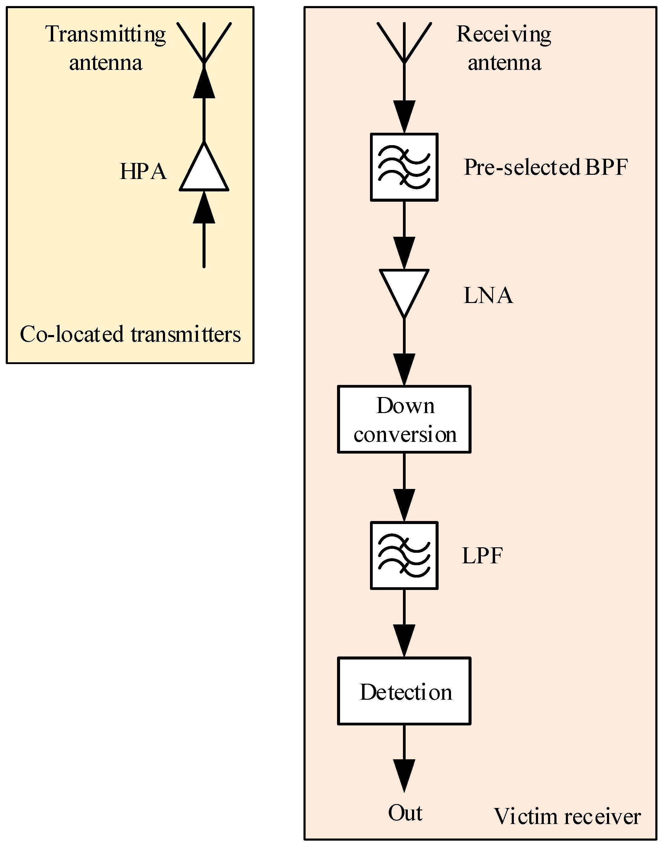
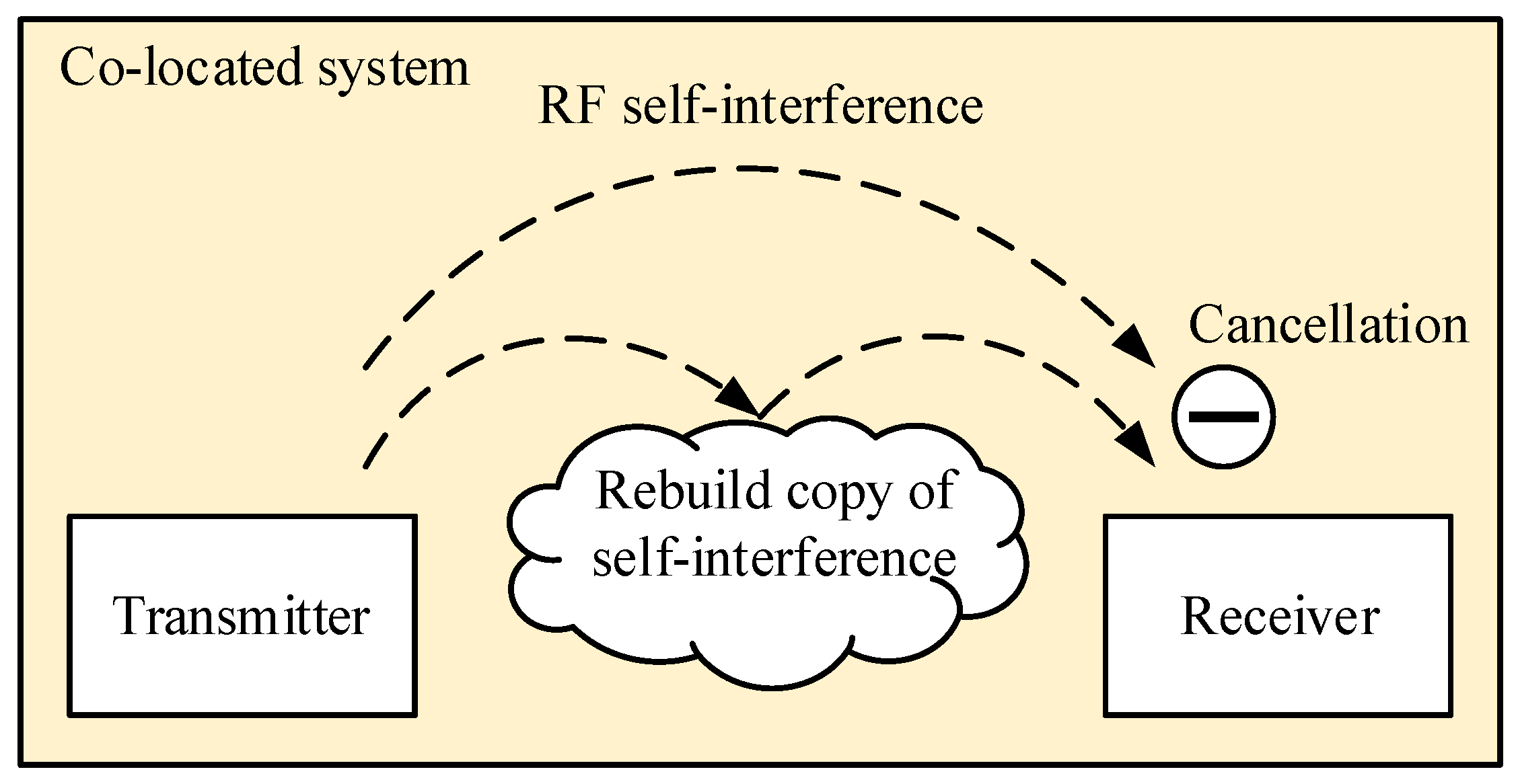
2. Phenomenon and Effects of Self-Interference
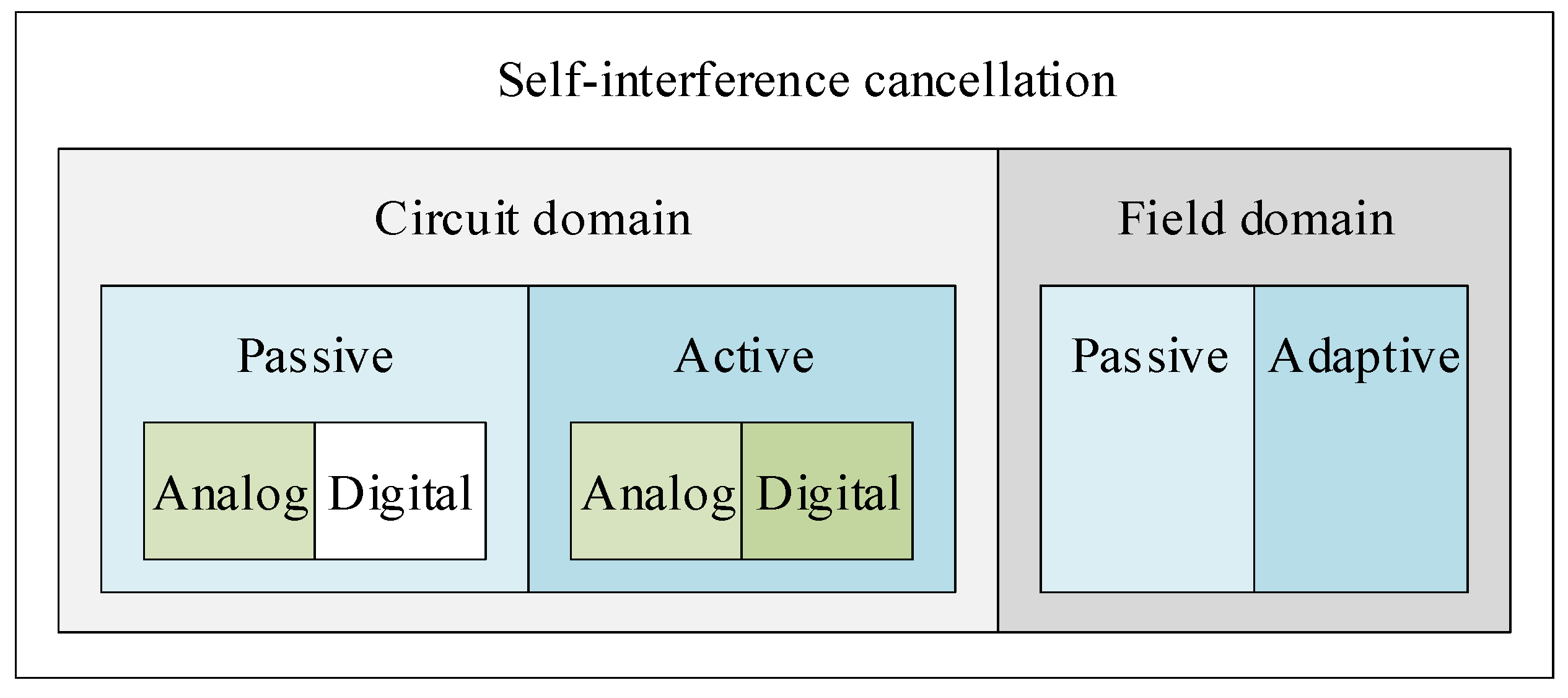
3. Classification of the SIC Techniques
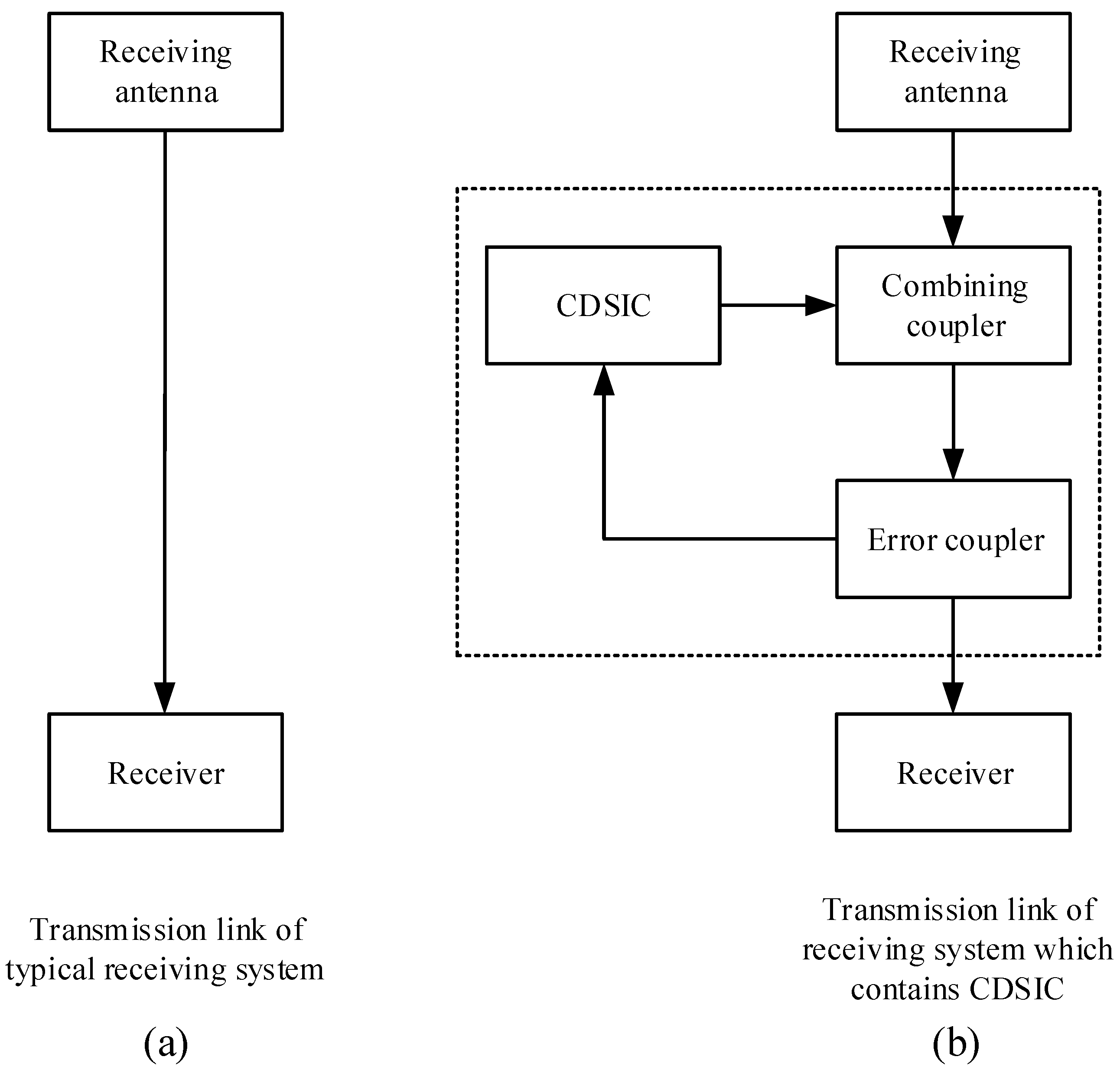
4. SIC via Analog and Digital Circuits
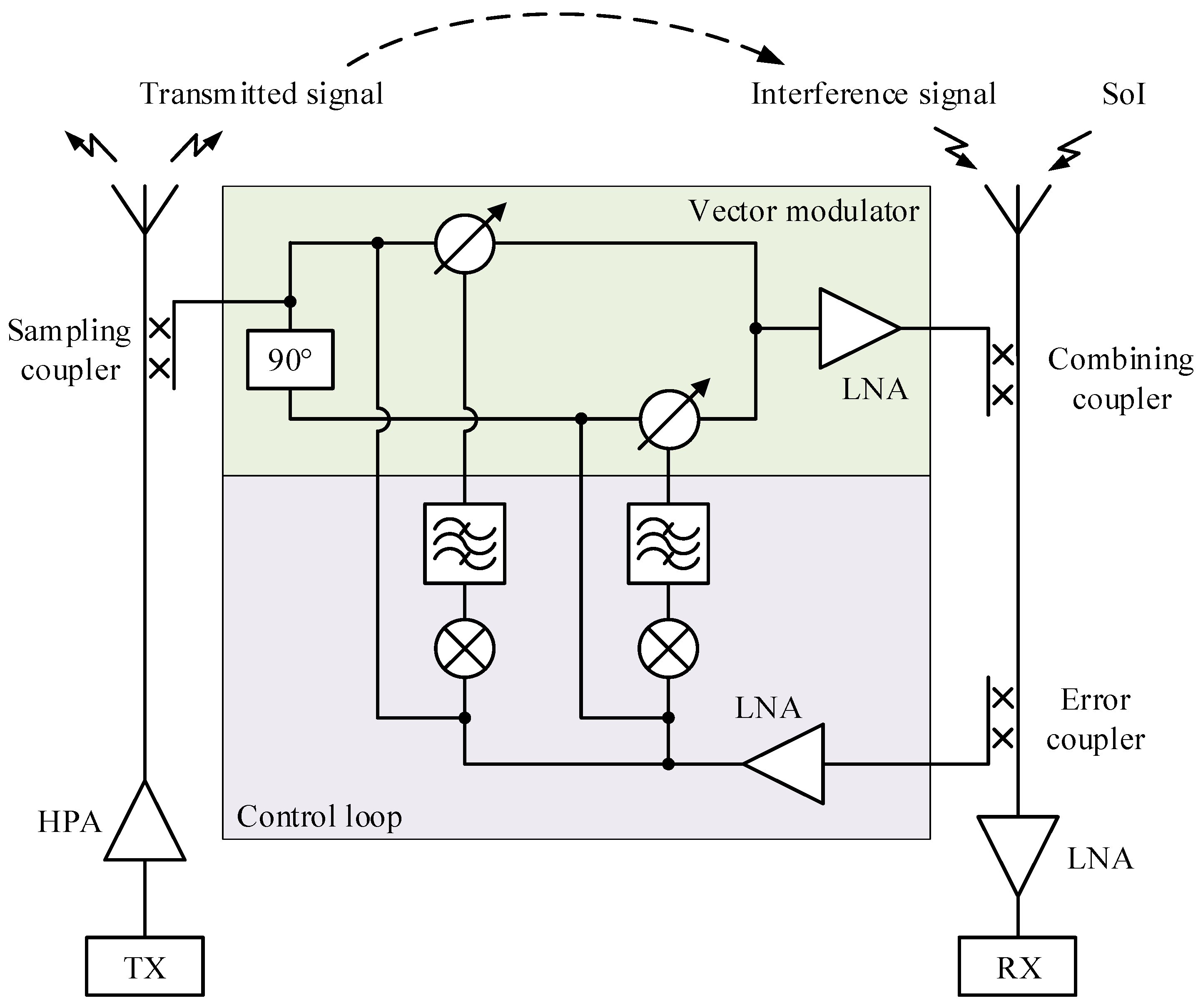
4.1. Analog SIC
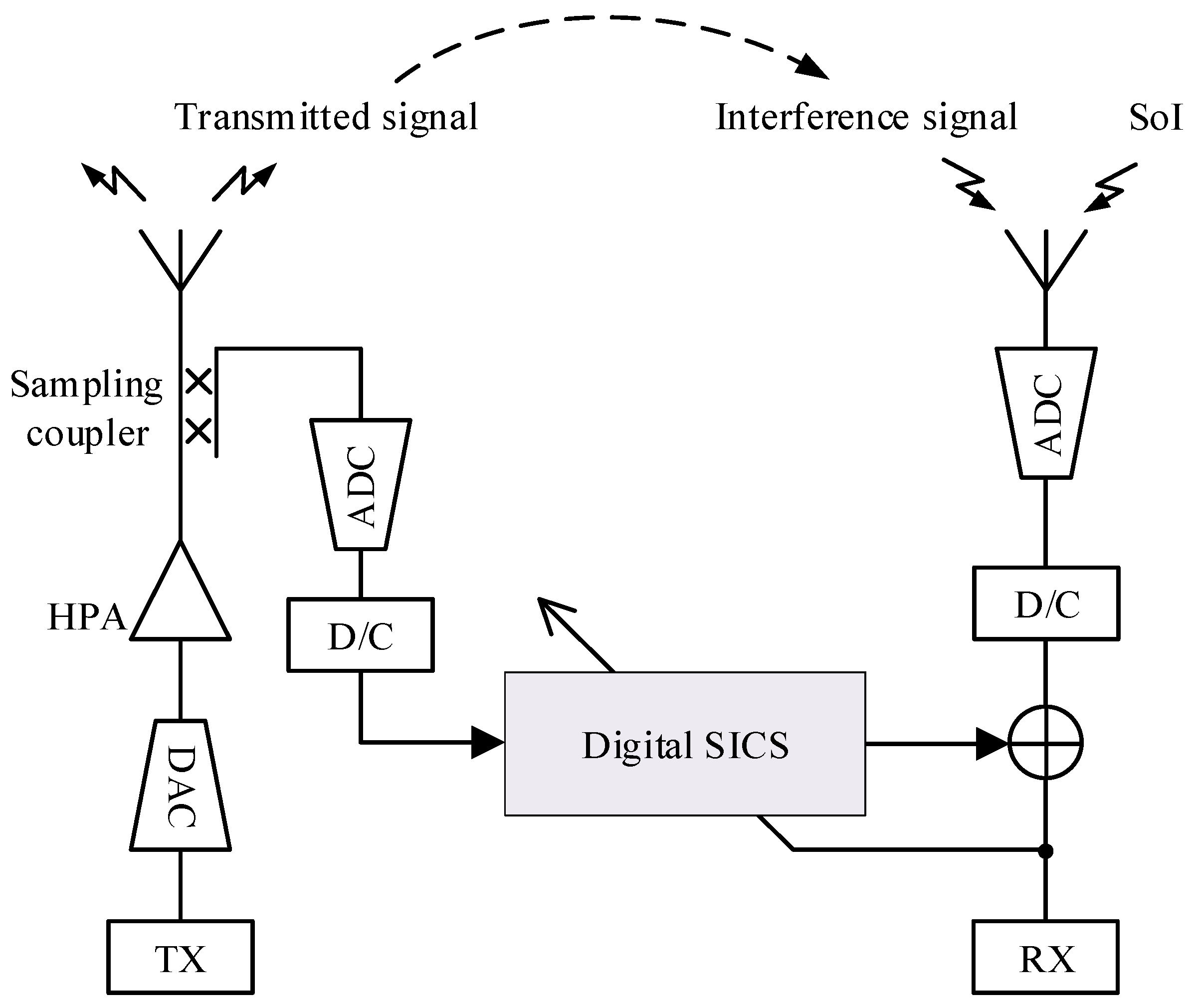
4.2. Digital SIC
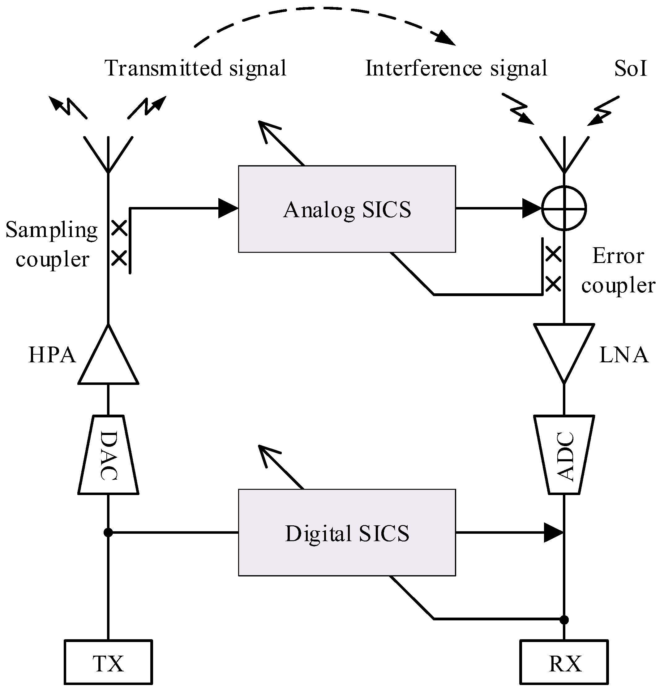
4.3. Analog–Digital Hybrid SIC
4.4. Passive SIC
4.5. Features of the Circuit-Domain SIC
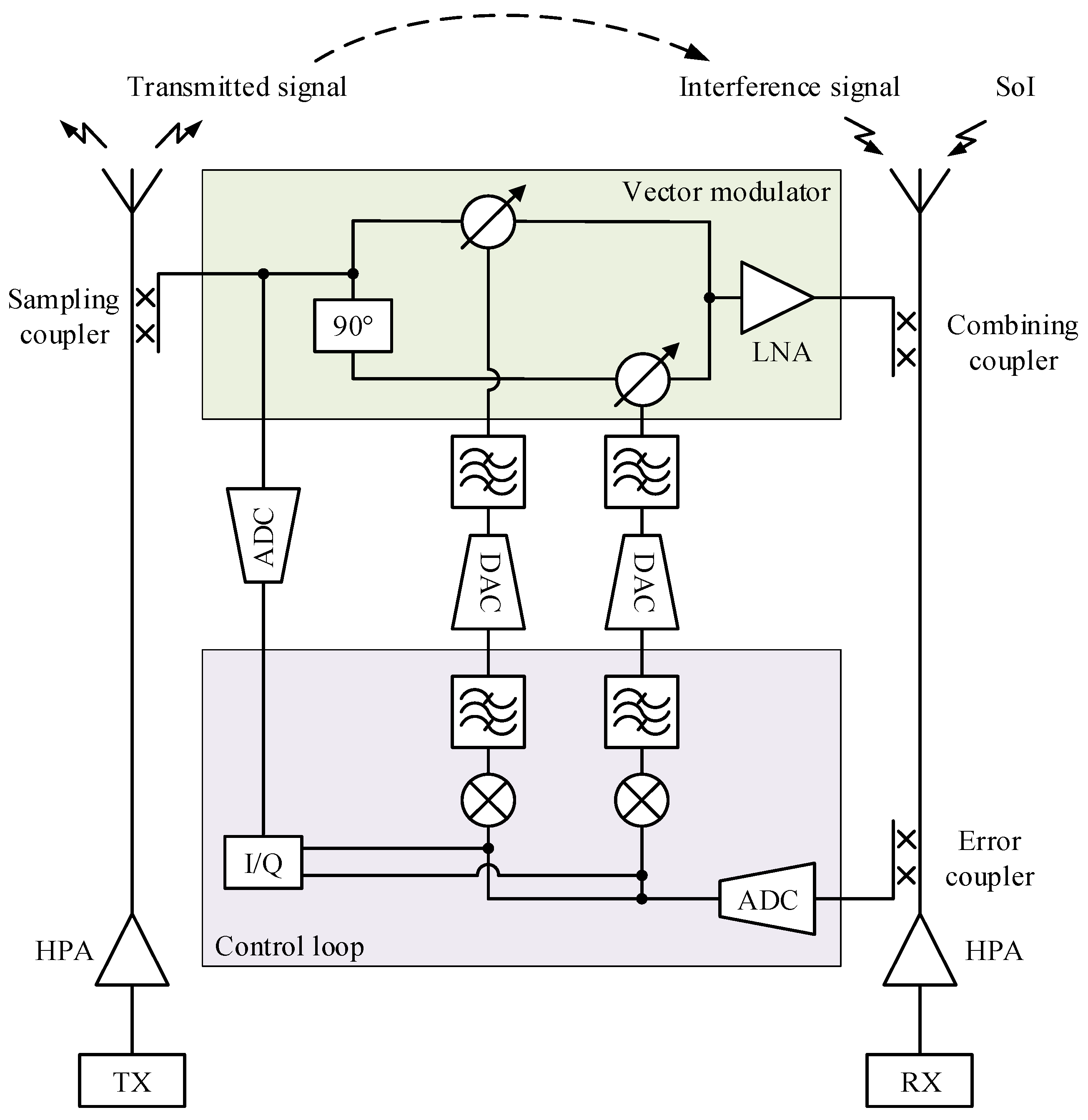
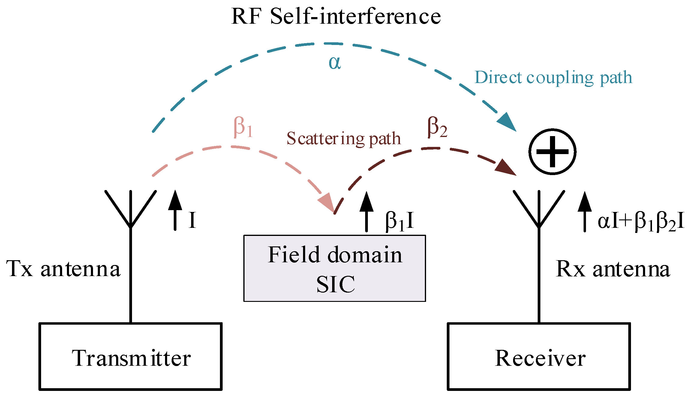
5. SIC in Fields Domain
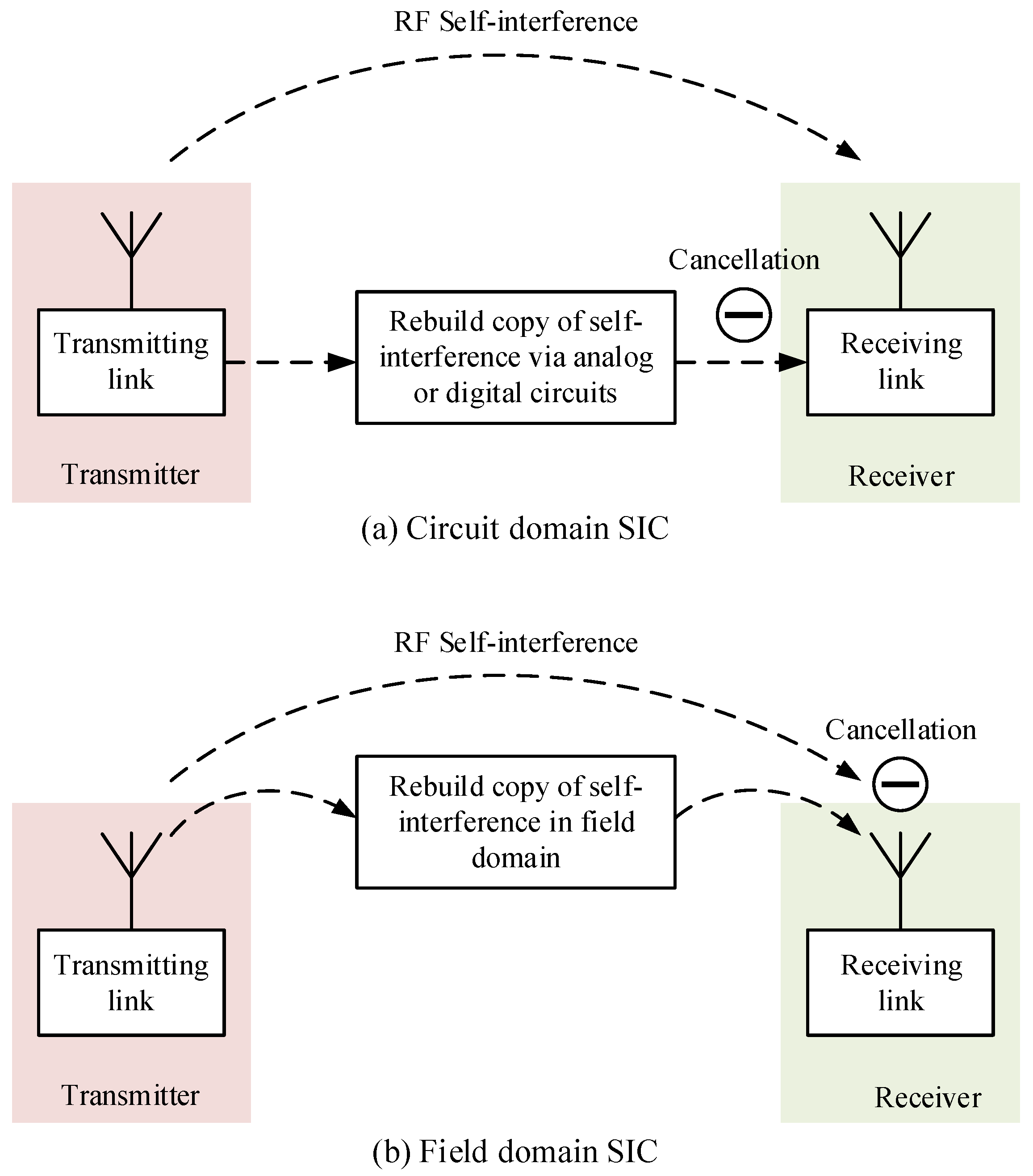
5.1. Operating Mechanism of the FDSIC
5.2. Features of the FDSIC
6. Comparison of the Circuit- and Field-Domain SIC
7. Conclusions
7.1. Concluding Remarks
7.2. Future Outlooks
Author Contributions
Funding
Conflicts of Interest
Abbreviations
| ADC | analog-to-digital converter |
| AI | artificial intelligence |
| CDSIC | circuit-domain self-interference cancellation |
| DAC | digital-to-analog converter |
| FDSIC | field-domain self-interference cancellation |
| HPA | high power amplifier |
| ICR | interference cancellation ratio |
| IM | intermodulation |
| LNA | low noise amplifier |
| LPF | low pass filters |
| SIC | self-interference cancellation |
| SICS | self-interference cancellation system |
| SoI | signal of interest |
| RF | radio frequency |
References
- Xue, W.; Li, F.; Chen, X. Effects of Signal Bandwidth on Total Isotropic Sensitivity Measurements in Reverberation Chamber. IEEE Trans. Instrum. Meas. 2021, 70, 1005408. [Google Scholar] [CrossRef]
- Lu, J.; Zhang, Q.; Shi, W.; Zhang, L.; Shi, J. Robust Adaptive Filtering Alogrithm for Self-Interference Cancellation with Impulsive Noise. Electronics 2021, 10, 196. [Google Scholar] [CrossRef]
- Akhtar, M.W.; Hassan, S.A.; Jung, H. On the Symbol Error Probability of STBC-NOMA with Timing Offsets and Imperfect Successive Interference Cancellation. Electronics 2021, 10, 1386. [Google Scholar] [CrossRef]
- Ershadi, A.; Entesari, K. A 0.5-to-3.5-GHz full-duplex mixer-first receiver with Cartesian synthesized self-interference suppression interface in 65-nm CMOS. IEEE Trans. Microw. Theory Tech. 2020, 68, 1995–2010. [Google Scholar] [CrossRef]
- Shah, M.; Cheema, H.M.; Abbasi, Q.H. Substrate Integrated Waveguide Antenna System for 5G In-Band Full Duplex Applications. Electronics 2021, 10, 2456. [Google Scholar] [CrossRef]
- Nawaz, H.; Shoaib, N.; Niazi, A.U.; Chaudhry, S.M. A Compact, Bistatic Antenna System with Very High Interport Isolation for 2.4 GHz In-Band Full Duplex Applications. Int. J. Antennas Propag. 2021, 2021, 8855726. [Google Scholar] [CrossRef]
- Zhang, Z.; Long, K.; Vasilakos, A.V.; Hanzo, L. Full-duplex wireless communications: Challenges, solutions, and future research directions. Proc. IEEE 2016, 104, 1369–1409. [Google Scholar] [CrossRef] [Green Version]
- Kolodziej, K.E.; McMichael, J.G.; Perry, B.T. Multitap RF canceller for in-band full-duplex wireless communications. IEEE Trans. Wirel. Commun. 2016, 15, 4321–4334. [Google Scholar] [CrossRef]
- Chen, X.; Xue, W.; Shi, H.; Yi, J.; Sha, W.E.I. Orbital Angular Momentum Multiplexing in Highly Reverberant Environments. IEEE Microw. Wirel. Compon. Lett. 2021, 30, 112–115. [Google Scholar] [CrossRef] [Green Version]
- Qin, H.; He, F.; Meng, J.; Wang, Q. Analysis and optimal design of radio-frequency interference adaptive cancellation system with delay mismatch. IEEE Trans. Electromagn. Compat. 2019, 6, 2015–2023. [Google Scholar] [CrossRef]
- Cheng, C.; Luo, L. Mutual Coupling Reduction Using Improved Dual-Layer Mushroom and E-Shaped Stub. Int. J. Antennas Propag. 2021, 2021, 8862570. [Google Scholar] [CrossRef]
- Qiu, L.; Zhao, F.; Xiao, K.; Chai, S.-L.; Mao, J.-J. Transmit–receive isolation improvement of antenna arrays by using EBG structures. IEEE Antennas Wirel. Propag. Lett. 2012, 11, 93–96. [Google Scholar]
- Niroo-Jazi, M.; Denidni, T.A.; Chaharmir, M.; Sebak, A. A hybrid isolator to reduce electromagnetic interactions between Tx/Rx antennas. IEEE Antennas Wirel. Propag. Lett. 2014, 13, 75–78. [Google Scholar] [CrossRef]
- Venkatakrishnan, S.B.; Alwan, E.A.; Volakis, J.L. Wideband RF self-interference cancellation circuit for phased array simultaneous transmit and receive systems. IEEE Access 2018, 6, 3425–3432. [Google Scholar] [CrossRef]
- Everett, E.; Sahai, A.; Sabharwal, A. Passive self-interference suppression for full-duplex infrastructure nodes. IEEE Trans. Wirel. Commun. 2014, 13, 680–694. [Google Scholar] [CrossRef] [Green Version]
- Dinc, T.; Krishnaswamy, H. A T/R antenna pair with polarization based wideband reconfigurable self-interference cancellation for simultaneous transmit and receive. Proc. IEEE MTT-S Int. Microw. Symp. 2015, 1–4. [Google Scholar] [CrossRef]
- Knox, M.E. Single antenna full duplex communications using a common carrier. In Proceedings of the WAMICON 2012 IEEE Wireless & Microwave Technology Conference, Cocoa Beach, FL, USA, 15–17 April 2012; pp. 1–6. [Google Scholar]
- Yang, S.; Vincent, D.; Bray, J.R.; Roy, L. Study of a ferrite LTCC multifunctional circulator with integrated winding. IEEE Trans. Compon. Packag. Manuf. Technol. 2015, 5, 879–886. [Google Scholar] [CrossRef]
- Lin, X.-J.; Xie, Z.-M.; Zhang, P.-S. Integrated Filtering Microstrip Duplex Antenna Array with High Isolation. Int. J. Antennas Propag. 2017, 2017, 4127943. [Google Scholar] [CrossRef] [Green Version]
- Li, Z.; Du, Z.; Takahashi, M.; Saito, K.; Tto, K. Reducing mutual coupling of MIMO antennas with parasitic elements for mobile terminals. IEEE Trans. Antennas Propag. 2012, 60, 473–481. [Google Scholar] [CrossRef]
- Lee, Y.; Ga, D.; Choi, J. Design of a MIMO Antenna with Improved Isolation Using MNG Metamaterial. Int. J. Antennas Propag. 2012, 2012, 864306. [Google Scholar] [CrossRef] [Green Version]
- Yon, H.; Rahman, N.H.A.; Aris, M.A.; Jamaluddin, M.H.; Kong Cheh Lin, I.; Jumaat, H.; Mohd Redzwan, F.N.; Yamada, Y. Development of C-Shaped Parasitic MIMO Antennas for Mutual Coupling Reduction. Electronics 2021, 10, 2431. [Google Scholar] [CrossRef]
- Ju, H.; Kim, D.; Poor, H.V.; Hong, D. Bi-directional beamforming and its capacity scaling in pairwise two-way communications. IEEE Trans. Wirel. Commun. 2012, 11, 346–357. [Google Scholar] [CrossRef]
- Zhou, J.; Chuang, T.-H.; Dinc, T.; Krishnaswamy, H. Integrated wideband self-interference cancellation in the RF domain for FDD and full-duplex wireless. IEEE J. Solid-State Circuits 2015, 50, 3015–3031. [Google Scholar] [CrossRef]
- Ahmed, S.; Faulkner, M. Interference at colocated base stations: A review. In Proceedings of the IEEE 23rd International Symposium on Personal, Indoor and Mobile Radio Communications (PIMRC), Sydney, NSW, Australia, 9–12 September 2012; pp. 1716–1721. [Google Scholar]
- Klumperink, E.A.M.; Nauta, B. Software defined radio receivers exploiting noise cancelling: A tutorial review. IEEE Commun. Mag. 2014, 111–117. [Google Scholar] [CrossRef]
- Venkatakrishnan, S.B.; Hovsepian, A.; Johnson, A.D.; Nakatani, T.; Alwan, E.A.; Volakis, J.L. Techniques for achieving high isolation in RF domain for simultaneous transmit and receive. IEEE Open J. Antennas Propag. 2020, 1, 358–367. [Google Scholar] [CrossRef]
- Gavan, J.J.; Shulman, M.B. Effects of Desensitization on Mobile Radio System Performance, Part I: Quantitative Analysis. IEEE Trans. Veh. Technol. 1984, VT-33, 285–290. [Google Scholar] [CrossRef]
- Huang, X.; Guo, Y.J. Radio frequency self-interference cancellation with analog least mean-square loop. IEEE Trans. Microw. Theory Tech. 2017, 65, 3336–3350. [Google Scholar] [CrossRef]
- Li, W.; Zhao, Z.; Tang, J.; He, F.; Li, Y.; Xiao, H. Performance analysis and optimal design of the adaptive interference cancellation system. IEEE Trans. Electromagn. Compat. 2013, 55, 1068–1075. [Google Scholar] [CrossRef]
- Zhang, Y.; Wang, Q.; Qin, H.; Meng, J. Adaptive self-interference cancellation system for microwave LFMCW radar with optimal delay matching. In Proceedings of the 2019 Joint International Symposium on Electromagnetic Compatibility, Sapporo and Asia-Pacific International Symposium on Electromagnetic Compatibility (EMC Sapporo/APEMC), Sapporo, Japan, 3–7 June 2019. [Google Scholar]
- Raghavan, A.; Gebara, E.; Tentzeris, E.M.; Laskar, J. Analysis and design of an interference canceller for collocated radios. IEEE Trans. Microw. Theory Tech. 2005, 53, 3498–3508. [Google Scholar] [CrossRef] [Green Version]
- Choi, Y.-S.; Shirani-Mehr, H. Simultaneous transmission and reception: Algorithm, design and system level performance. IEEE Trans. Wirel. Commun. 2013, 12, 5992–6010. [Google Scholar] [CrossRef] [Green Version]
- Bharadia, D.; McMilin, E.; Katti, S. Full duplex radios. In Proceedings of the ACM SIGCOMM 2013 Conference on SIGCOMM, Hong Kong, China, 12–16 August 2013; pp. 375–386. [Google Scholar]
- Kolodziej, K.E.; Yegnanarayanan, S.; Perry, B.T. Fiber bragg grating delay lines for wideband self-interference cancellation. IEEE Trans. Microw. Theory Tech. 2019, 67, 4005–4014. [Google Scholar] [CrossRef]
- Le, A.T.; Tran, L.C.; Huang, X.; Gou, Y.J.; Vardaxoglou, J.C. Frequency-domain characterization and performance bounds of ALMS loop for RF self-interference cancellation. IEEE Trans. Commun. 2019, 67, 682–692. [Google Scholar] [CrossRef]
- Zhao, K.; Wang, Q.; He, F.; Cui, Z.; Meng, J.; Zhang, L. Analysis of interference cancellation ratio requirement for co-site interference mitigation between AM and FM systems. In Proceedings of the 2019 Joint International Symposium on Electromagnetic Compatibility, Sapporo and Asia-Pacific International Symposium on Electromagnetic Compatibility (EMC Sapporo/APEMC), Sapporo, Japan, 3–7 June 2019. [Google Scholar]
- Ma, M.; Huang, X.; Gou, Y.J. An interference self-cancellation technique for SC-FDMA systems. IEEE Commun. Lett. 2010, 14, 512–514. [Google Scholar] [CrossRef]
- He, Z.; Shao, S.; Shen, Y.; Qing, C.; Tang, Y. Performance analysis of RF self-interference cancellation in full-duplex wireless communications. IEEE Wirel. Commun. Lett. 2014, 3, 405–408. [Google Scholar] [CrossRef]
- Choi, J.I.; Jain, M.; Srinivasan, K.; Levis, P.; Katti, S. Achieving single channel, full duplex wireless communications. In Proceedings of the Sixteenth Annual International Conference on Mobile Computing and Networking, Chicago, IL, USA, 20–24 September 2010; pp. 1–12. [Google Scholar]
- Duarte, M.; Sabharwal, A. Full-duplex wireless communications using off-the-shelf Radios: Feasibility and first results. Proc. Asilomar Conf. Signals Syst. Comput. 2010, 1558–1562. [Google Scholar] [CrossRef]
- Shen, L.; Henson, B.; Zakharov, Y.; Mitchell, P. Digital Self-Interference Cancellation for Full-Duplex Underwater Acoustic Systems. IEEE Trans. Circuits Syst.-II Express Briefs 2020, 67, 192–196. [Google Scholar] [CrossRef] [Green Version]
- Ahmed, E.; Eltawil, A.M. All-digital self-interference cancellation technique for full-duplex systems. IEEE Trans. Wirel. Commun. 2015, 14, 3519–3532. [Google Scholar] [CrossRef] [Green Version]
- Masmoudi, A.; Le-Ngoc, T. Channel estimation and self-interference cancelation in full-duplex communication systems. IEEE Trans. Veh. Technol. 2017, 66, 321–334. [Google Scholar] [CrossRef]
- Laughlin, L.; Beach, M.A.; Morris, K.A.; Haine, J.L. Optimum single antenna full duplex using hybrid junctions. IEEE J. Sel. Areas Commun. 2014, 32, 1653–1661. [Google Scholar] [CrossRef] [Green Version]
- Ge, S.; Xing, J.; Liu, Y.; Liu, H.; Meng, J. Dual-stage co-site RF interference canceller for wideband direct-conversion receivers using reduced observation chain. IEEE Trans. Electromagn. Compat. 2020, 62, 923–932. [Google Scholar] [CrossRef]
- Liu, J.; Quan, H.; Li, Z.; Sun, H.; Yuan, D. Digital nonlinear self-interference cancellation based on LMS-volterra algorithm. In Proceedings of the 2016 3rd International Conference on Information Science and Control Engineering, Beijing, China, 8–10 July 2016. [Google Scholar]
- Liu, Y.; Roblin, P.; Quan, X.; Pan, W.; Shao, S.; Tang, Y. A full-duplex transceiver with two-stage analog cancellations for multipatch self-interference. IEEE Trans. Microw. Theory Tech. 2017, 65, 5263–5273. [Google Scholar] [CrossRef]
- Duarte, M.; Dick, C.; Sabharwal, A. Experiment-driven characterization of full-duplex wireless systems. IEEE Trans. Wirel. Commun. 2012, 11, 4296–4307. [Google Scholar] [CrossRef] [Green Version]
- Liu, Y.; Quan, X.; Pan, W.; Tang, Y. Digitally assisted analog interference cancellation for in-band full-duplux radios. IEEE Commun. Lett. 2017, 21, 1079–1082. [Google Scholar] [CrossRef]
- Ge, S.; Meng, J.; Xing, J.; Liu, Y.; Gou, C. A digital-domain controlled nonlinear RF interference cancellation scheme for co-site wideband radios. IEEE Trans. Electromagn. Compat. 2018, 61, 1647–1654. [Google Scholar] [CrossRef]
- Xing, J.; Ge, S.; Liu, Y.; Cui, Z.; Meng, J. Comprehensive analysis of quantization effects on digital-controlled adaptive self-interference cancellation system. IEEE Access 2020, 8, 75772–75784. [Google Scholar] [CrossRef]
- Makimura, H.; Nishimoto, K.; Yanagi, T.; Fukasawa, T.; Miyashita, H. Novel decoupling concept for strongly coupled frequency-dependent antenna arrays. IEEE Trans. Antennas Propag. 2017, 65, 5147–5154. [Google Scholar] [CrossRef]
- Zhang, Y.; Zhang, S.; Li, J.; Pedersen, G.F. A transmission-line-based decoupling method for MIMO antenna arrays. IEEE Trans. Antennas Propag. 2019, 67, 3117–3131. [Google Scholar] [CrossRef] [Green Version]
- Bhatti, R.A.; Yi, S.; Park, S.-O. Compact antenna array with port decoupling for LTE-standardized mobile phones. IEEE Antennas Wirel. Propag. Lett. 2009, 8, 1430–1433. [Google Scholar] [CrossRef]
- Chaudhary, G.; Jeong, J.; Jeong, Y. Differential fed antenna with high self-interference cancellation for in-band full-duplex communication system. IEEE Access 2019, 7, 45340–45348. [Google Scholar] [CrossRef]
- Zhang, J.; Yan, S.; Hu, X.; Vandenbosch, G.A.E. Mutual coupling suppression for on-body multiantenna systems. IEEE Trans. Electromagn. Compat. 2020, 22, 1045–1054. [Google Scholar] [CrossRef]
- Zhang, J.; Akinsolu, M.O.; Liu, B.; Vandenbosch, G.A.E. Automatic AI-driven design of mutual coupling reducing topologies for frequency reconfigurable antenna arrays. IEEE Trans. Antennas Propag. 2021, 69, 1831–1836. [Google Scholar] [CrossRef]
- Zhang, L.; Zhang, S.; Song, Z.; Liu, Y.; Ye, L.; Liu, Q.H. Adaptive decoupling using tunable metamaterials. IEEE Trans. Microw. Theory Tech. 2016, 64, 2730–2739. [Google Scholar] [CrossRef]
- Tang, J.; Zhao, Z.; Li, W.; Meng, J.; Li, Y.; He, F.; Xiao, H. Research on noise figure of a receiving system using adaptive interference cancellation. In Proceedings of the Asia-Pacific International Symposium on Electromagnetic Compatibility (APEMC2016), Shenzhen, China, 17–21 May 2016. [Google Scholar]
- Park, H.; Park, J.; Kim, S.; Cho, K.; Lho, D.; Jeong, S.; Park, S.; Park, G.; Sim, B.; Kim, S.; et al. Deep reinforcement learning-based optimal decoupling capacitor design method for silicon interposer-based 2.5-D/3-D ICs. IEEE Trans. Compon. Packag. Manuf. Technol. 2020, 10, 467–478. [Google Scholar] [CrossRef]
- Wang, Q.; He, F.; Meng, J. Performance comparison of real and complex valued neural networks for digital self-interference cancellation. In Proceedings of the IEEE 19th International Conference on Communication Technology (ICCT2019), Xi’an, China, 16–19 October 2019. [Google Scholar]


| Ref | Category | Complexity | ICR | Bandwidth |
|---|---|---|---|---|
| [29] | CDSIC-analog | High | 30–40 dB | narrow |
| [30] | CDSIC-analog | High | 60–80 dB | narrow |
| [32] | CDSIC-analog | High | ca. 30 dB | narrow |
| [35] | CDSIC-analog | High | ca. 30 dB | wide |
| [43] | CDSIC-digital | High | 25–60 dB | narrow |
| [46] | CDSIC-hybrid | High | 30–40 dB | wide |
| [53] | CDSIC-passive | Low | 12 dB | narrow |
| [56] | CDSIC-passive | Low | 60 dB | narrow |
| [58] | FDSIC-passive | Low | ca. 8 dB | narrow |
| [59] | FDSIC-active | High | 40 dB | narrow |
| Transmitting Power Loss | Attenuation of the SoI | Effect on the Noise Figure | Radiation Pattern | ||
|---|---|---|---|---|---|
| Circuit domain | Analog | Yes | Yes | Yes | No effect |
| Digital | Yes | Yes | Yes | No effect | |
| Field domain | - | No loss | No attenuation | No effect | Distortion |
Publisher’s Note: MDPI stays neutral with regard to jurisdictional claims in published maps and institutional affiliations. |
© 2022 by the authors. Licensee MDPI, Basel, Switzerland. This article is an open access article distributed under the terms and conditions of the Creative Commons Attribution (CC BY) license (https://creativecommons.org/licenses/by/4.0/).
Share and Cite
Zhang, J.; He, F.; Li, W.; Li, Y.; Wang, Q.; Ge, S.; Xing, J.; Liu, H.; Li, Y.; Meng, J. Self-Interference Cancellation: A Comprehensive Review from Circuits and Fields Perspectives. Electronics 2022, 11, 172. https://doi.org/10.3390/electronics11020172
Zhang J, He F, Li W, Li Y, Wang Q, Ge S, Xing J, Liu H, Li Y, Meng J. Self-Interference Cancellation: A Comprehensive Review from Circuits and Fields Perspectives. Electronics. 2022; 11(2):172. https://doi.org/10.3390/electronics11020172
Chicago/Turabian StyleZhang, Jiahao, Fangmin He, Wei Li, Yi Li, Qing Wang, Songhu Ge, Jinling Xing, Hongbo Liu, Yaxing Li, and Jin Meng. 2022. "Self-Interference Cancellation: A Comprehensive Review from Circuits and Fields Perspectives" Electronics 11, no. 2: 172. https://doi.org/10.3390/electronics11020172