
Prototype Verification of Self-Interference Suppression for Constant-Amplitude Full-Duplex Phased Array with Finite Phase Shift

Nanjing Research Institute of Electronics Technology, Nanjing 210096, China
*
Author to whom correspondence should be addressed.
Electronics 2022, 11(3), 295; https://doi.org/10.3390/electronics11030295
Submission received: 10 November 2021
/
Revised: 10 December 2021
/
Accepted: 12 December 2021
/
Published: 18 January 2022
(This article belongs to the Special Issue EMC Analysis in Wireless Communication)
Abstract
:In view of the strong self-interference problem when the practical phased array system is simultaneously applied for transmission and reception, under the constraints including limited quantization number, constant envelope amplitude, scanning mode, wideband signal mode, etc., this work studies it and proposes the amplitude-phase joint adjustment method and the phase-only method for beamforming optimization. Through digital simulation design, electromagnetic simulation evaluation and principle test verification, under the actual array system conditions, including 6-bit phase quantization or phase step size of 5.625° and amplitude 0.5 dB quantization step, when the transmitting beam is pointing (0°, 0°), the research has achieved a performance of 11.9~14.4 dB for self-interference suppression; at the same time, the optimized beam shape is maintained well, and the ratio of the main lobe to the side lobes does not change significantly, but the beam gain has a loss of about 2~3 dB. In addition, we studied the interference suppression performance and beam feature retention performance of the optimized beamforming weights in the case of array scanning and broadband signals, and analyzed the influence of the changes in the mutual coupling characteristics between elements caused by scanning and frequency changes on the cancellation performance. This provides a reference for the application research of the simultaneous transmitting and receiving self-interference suppression technology in the actual array system state.
1. Introduction
Nowadays radio systems, including radar, communication and multifarious electronic warfare support measures, mainly use a half-duplex (HD) mode with transmitting and receiving functions. For the sake of effectively utilizing the time, frequency and space resources, with the development of a radio hardware system, especially adaptive signal processing, the innovative FD method is proposed to compensate the deficiencies of HD. While FD can bring many benefits, the serious problem in its practical realization is the strong self-interference (SI) between the transmitter and the receiver during their simultaneous operation, which can heavily barrage the receiver, and make it impossible to receive the signal of interest arriving from a remote transmission or return weak signal [1,2].
The goal of full-duplex technology is to transmit and receive simultaneously in the same frequency band at the same time. In this case, the RF system not only receives the signal of interest, but also receives the coupling or leakage signal that is transmitted, which becomes the essential problem for simultaneous transmit and receive in a radio system. Self-interference signal strength on the receiving ends therefore must be reduced sufficiently to satisfy that the radio system’s own transmission does not interfere with its normal reception of the signal of interest. Especially for phased array systems with multiple transceiver units, the self-interference components and magnitude will be significantly higher than conventional RF systems.
For achieving sufficient isolation between transmission and reception, there is usually a need to combine different technologies, including spatial isolation suppression, analog and digital cancellation. In the application of a single channel FD radio system, these technologies can be integrated to satisfy the need for SI suppression. While for phased array, especially digital phased array, which has hundreds of antenna cells, the mutual coupling paths among different elements are profuse. To apply the FD method in phased array, the complex channel’s characteristic of the coupling paths must be analyzed and modeled before SI cancellation using relevant technologies [3,4,5,6].
In [7,8], the ALSTAR configuration of a phased array for simultaneous transmission and reception was proposed and simulated, and preliminary experiments with a one-dimensional linear array of eight elements were carried out. However, their work mainly considers the situation that the amplitude and phase of the array can be adjusted. In [9], Liu et al. studied full-duplex millimeter wave communication based on beamforming mainly focused on the controllable amplitude and phase of the array weights. In [10], Xiao et al. propose several candidate phase-only beamforming vector solutions used for phased array. However, their work gives simulation results for millimeter wave communication. In [11,12], Cummings et al. simulated transmit/receive aperture partition optimization via genetic algorithm for the ALSTAR architecture, and the amplitude and phase of the element weights are controllable.
Through a comprehensive analysis of relevant literature [7,8,9,10,11,12,13,14,15,16,17,18,19,20,21,22,23,24,25,26], we can see that, as an important key technology to realize the elimination of simultaneous coupling interference suppression in phased array system, it is a necessary way to realize the unsaturation of the receiving channel of large array system while taking into account the realization of the system by making full use of the multi-unit multi-freedom characteristics in the array system airspace/transmission domain to suppress self-interference. On the basis of the phased array digital domain adaptive system identification and cancellation filtering principle and experimental research [24], as the first level of the interference suppression multi-level method, the work here is mainly for the actual phased array system aperture-level simultaneous transmit and receive realization of self-interference suppression in transmission domain [8,23,25], the principle model and corresponding optimization methods under the practical limiting factors such as limited quantization number, constant envelope amplitude, scanning mode, wideband signal mode, etc. [27,28].
Take practical finite bit quantization as an example for the actual phased array system, the phase control of each element is carried out through a phase shifter with a certain number of digits, such as 6~8 bits. Therefore, the actual suppression of coupling interference between array elements must consider two factors. One is that only the phase is controllable due to the power efficiency of the amplifier; the other is the limiting factor of the discretization of the actual phase shift value caused by the finite number of phase shifters. If the conventional phase-only optimization method is used to obtain the optimized phase-only control value, the optimized value needs to be approximated to the closest discrete value for the actual array system application, which may cause a certain optimization deviation. For this reason, we use the genetic optimization algorithm to directly encode and evolutionally optimize the phase shift value of the finite-digit phase shifter, and then the relatively optimal phase shift value can be directly obtained [22].
Similarly, for the transmission constant envelope, scanning mode and wideband signal that will occur in the actual array system application, most of the previous related documents did not systematically involve this type of practical research. The work of this paper will conduct modeling analysis and principle verification research on these practical problems.
This paper is structured as follows. Section 2 introduces the array coupling self-interference cancellation model for single frequency signal and wideband signal, and for finite phase-shift constant-amplitude full-duplex phased array. The electromagnetic modeling simulation and experimental verification is given in Section 3. Section 4 summarizes the paper and prospects the future work.
2. Phased Array Coupling Self-Interference Suppression Model
2.1. Phased Array Coupling Self-Interference Suppression Model of Conventional Single Frequency Signal
For an array system, the transmitting and receiving sub-arrays are respectively configured with N transmitting elements and M receiving elements. Set the channel transmission characteristics of the n-th (n = 1, …, N) transmitting element to the m-th (m = 1, …, M) receiving element as , where is the amplitude attenuation coefficient and is the phase change amount [8,23,29,30].
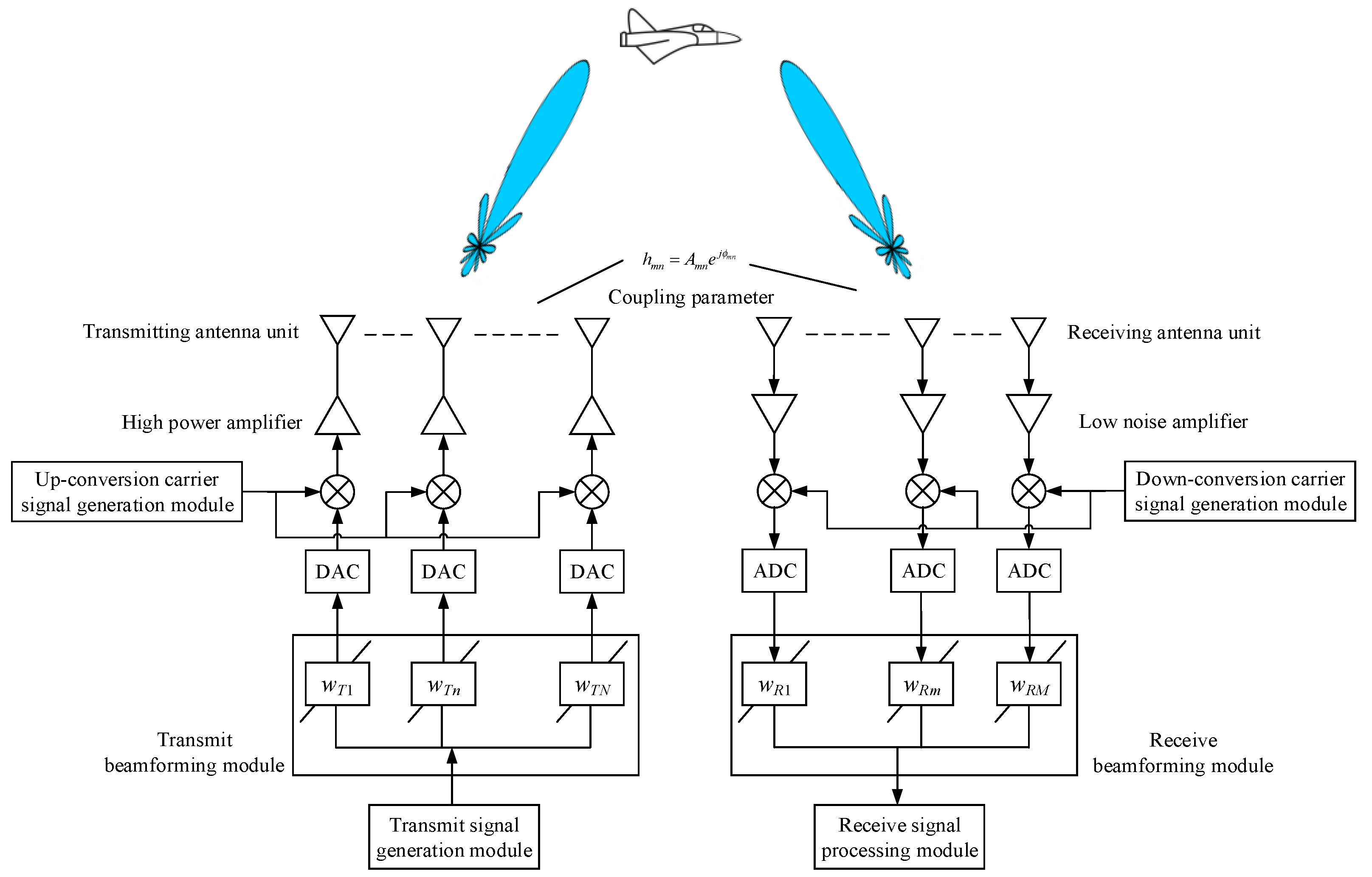
The phased array applies beamforming weight vectors to each of its antenna elements to generate a directional transmit Tx/receive Rx beam pattern [29,30]. Let denote the weighting value of the -th transmitting antenna unit, and corresponding to the transmitting weight vector of the transmitting phased array of N antennas. Let denote the weighting value of the m-th receiving antenna unit, and represents the receiving weight vector of the receiving phased array corresponding to M antennas. Figure 1 shows the basic full-duplex self-interference spatial beam optimization interference suppression principle of a phased array antenna array with N transmitting units and a phased antenna array with M receiving units.
According to the basic coupling characteristics relationship between the phased array antenna elements, the self-coupling interference signal received by the phased array of the single-input single-output system commonly used in radar systems can be simply expressed by the following equation [7,8,31,32]:
where represents the transmitted single frequency signal; is the self-interference coupling matrix between the transmitting and receiving antenna units at frequency ; is the self-interference coupling coefficient between the receiving antenna unit and the transmitting antenna unit ; denotes additive white Gaussian noise. Let , the self-interference power of the transmitting signal to the receiving antenna is , where the superscript represents the conjugate transpose.
As we can see from the above equation, the self-interference channel characteristics directly determines the complexity of coupled self-interference and the feasibility of its suppression methods. Because the practical array antenna has complex three-dimensional configuration, the simple near-field model is not strictly accurate for characterization of the coupling interference in array system [9,10]. For better modeling channel characteristics of coupling interference in this experimental array, we introduce electromagnetic model of the array based on Ansoft HFSS(High Frequency Structure Simulator). The HFSS apply FEM (Finite Element Method) to calculate the S-parameter matrix and full-wave electromagnetic field of arbitrary array antenna configuration.
The -th row and -th column of the matrix are represented as , which represents the coupling relationship between the -th and -th elements in the array. is the total number of elements in the array. Based on the -parameter matrix , we define the element the of the array in -th row and in the -th column of the interference channel characteristic matrix , as:
In the formula, is the unit number of the sub-array set for transmitting and/or receiving in the entire array, is the unit set corresponding to the transmitting sub-array, M is the number of units of the transmitting sub-array and N is the number of units of the receiving sub-array. is the set of units corresponding to the receiving sub-array. For the separated-aperture array-level simultaneous transceiver mode, there is ; for the partial array-level/partial unit-level simultaneous transceiver mode, there is . Especially for the full-aperture unit-level transceiver simultaneous mode, there is .
Firstly, taking the transmit beam optimization model as an example, the optimization of its weights has two purposes. One is to reduce the self-interference (SI) of the phased array transmitting unit to the receiving unit, and the other is to provide a high transmit beamforming gain level in a desired direction [7,8,23,25,29,30,33].
The power of the transmitted signal in the radio frequency (RF) domain at the receiving antenna unit is equal to . The self-interference power received by multiple receiving units of the receiving array can have different optimization models, such as minimizing the sum value and minimizing the maximum value. Here, the maximum value refers to the maximum interference power coupled to the receiving array unit when the transmitting array is transmitting. The purpose of minimizing the maximum value is to make the maximum interference power less than the saturation value of the receiving channel, so as to ensure the normal operation of the receiving channel. On the one hand, for analog arrays, reducing the self-interference (SI) of the receiving array antenna is to minimize the total RF domain SI power. There are two considerations for this choice: (1) Minimizing the total SI power reduces the RF domain SI power of each unit, thereby obtaining the SI reduction for any receiving analog beamformer . (2) Minimizing the total SI gives the analog beamformer more degrees of freedom to generate nulls, that is, instead of generating nulls at a specific antenna unit position, this method can reduce SI at multiple antenna positions through methods such as zero forcing [29]. On the other hand, for digital arrays [34], reducing the power of the receiving components of each unit is a prerequisite to ensure that the low-noise amplifier of the receiver components is not saturated. Therefore, setting the optimization target to the minimization of the maximum coupling interference power (MoMCIP) is a feasible optimization criterion to avoid saturation of the receiving element.
Now we consider the optimization of minimizing the deterministic transmit signal coupled to the sum of the components of all receiving antenna arrays. Therefore, after combined with the saturation power of the transmitting component and set as the limit of , the transmit beam optimization problem is expressed as
where ; represents the direction of the transmit beam; represents the spacing between units; represents the wavelength corresponding to the operating frequency .
Solution:
The Singular Value Decomposition (SVD) decomposition of the matrix of the self-interference channel is as follows:
where , are unitary matrices; is a diagonal matrix that contains the singular values of in descending order. Based on the concept of matrix null space, the row of (column of ) in the SVD of the self-interference channel represents the basis set of orthogonal receiving (transmitting) beamforming vectors. , is the zero space of , and its column vectors form an orthogonal basis. Thus, according to the concept of orthogonal space, in order to suppress the coupling of the transmitted signal to the interference signal at the receiving antenna unit, the transmit beamforming/precoding can be expressed as , where is the transmit beamforming/coding matrix.
According to the analysis of the fundamental phased array principle, the condition for the conventional beam to point in the direction of is that the weight is taken as . In order to suppress the array coupling self-interference, the null space of the self-interference channel is set to , is the column vector of and the optimized beamforming weight vector is expressed as:
where satisfies the following equation:
In the formula, represents the inner product of vector and vector represents the inner product of vector and vector , and the subscript .
For the weight optimization of receiving beamforming, the calculation model and its optimization solution are analyzed as follows. Let be denote as , where denotes represents the self-interference channel vector between the receiving antenna unit and the n-th transmitting antenna unit. The signal power of the n-th transmitting antenna unit received at the receiving antenna units is equal to . Considering the spatial coupling, the sum of the components of a specific unit at different transmitting positions coupled to the receiving antenna array is minimized. Therefore, the problem of receiving beam optimization is expressed as
It is equivalent to
where ; represents the direction of the receive beam. The solution is the same as the beamforming optimization method at the transmitter, but the difference is that on the basis of the optimized transmit beam, SVD is used to decompose the self-interference channel and the corresponding null space is constructed. Then the received beamforming/coding matrix is obtained by projecting onto , which is substituted into the relation . That is to say, a receiving beamforming filter is obtained to suppress the interference of different transmitting units coupled to the receiving array.
2.2. Self-Interference Suppression Model of Finite Phase-Shift Constant-Amplitude Full-Duplex Phased Array
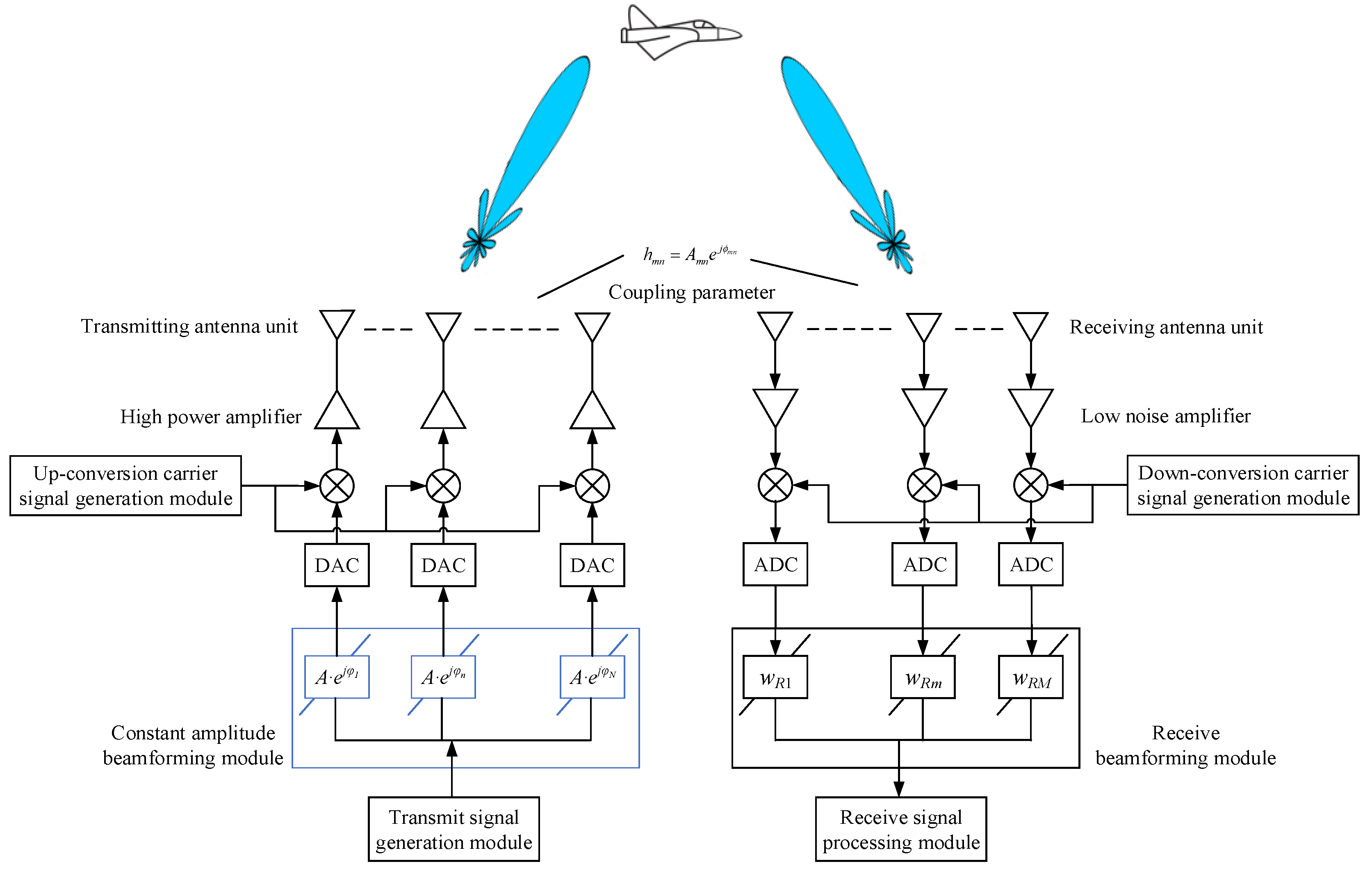
For a phased array system using saturated power amplification and transmission, it is assumed that the transmitting array and the receiving array are composed of N transmitting units and M receiving units respectively. The phased array applies beamforming weight vectors to each antenna element to generate a directional beam pattern. Take the actual phased array system with a constant transmission weight amplitude, only the phase shifter can be adjusted as an example let denote the weighted value of the transmitting antenna unit , and denote the constant amplitude of the weighted value. Therefore, Figure 2 shows the beam optimization principle diagram of a phased array antenna array with constant amplitude transmitting units and a phased antenna array with receiving units.
According to the above model description and related parameter definitions, a constant amplitude phased array beamforming optimization method based on genetic evolution algorithm for full-duplex applications is proposed, which can effectively suppress the coupling self-interference of the array while ensuring the beam characteristics. The implementation steps are as follows:
(a) Obtain the self-interference coupling matrix between the transceiver arrays
According to the distribution characteristics of the array system to realize the simultaneous full-duplex transmission and reception, the self-interference coupling characteristics between the transmitting array and the receiving array are calculated through electromagnetic coupling test or simulation to obtain the self-interference coupling matrix between the transmitting and receiving antenna units; and is the self-interference coupling coefficient between the receiving antenna unit and the transmitting antenna unit .
(b) Establish a coupling interference suppression optimization model with constant amplitude beamforming weights
First, the characteristic modeling of the coupling interference from the transmitting array to the receiving array is characterized as:
where is the coupling self-interference characteristic between the N transmitting units of the transmitting array and the m-th receiving unit, namely ; is the weight corresponding to N transmitting units.
Secondly, suppose the direction of the transmitting beam is the azimuth angle θ and the elevation angle γ then the corresponding spatial steering vector is:
where is the vector describing the abscissa position of all transmitting antennas, and is the vector describing the ordinate position of all transmitting antennas.
From the above, the corresponding transmit beam gain is . For the optimization of the weights, in order to ensure the beam pointing azimuth angle θ and elevation angle γ, while minimizing the coupling self-interference of the array, and maintaining the sidelobe characteristics of the formed transmitting beam, the optimization model of the constant amplitude weight is characterized as:
where is the array transmit gain of the transmitting array when the beam is directed to the direction under the weight ; is the scaling factor that minimizes the total optimization objective cost function of the array transmission gain; is the coupling self-interference feature between the transmitting units of the transmitting array and the nth receiving unit; is the weight of the corresponding transmitting units; is the scaling factor that minimizes the total optimization objective cost function of the coupling self-interference of the transmitting array to the receiving array; is the peak sidelobe ratio of the transmitting array under the weight ; is the scaling weight of the peak sidelobe comparison optimization objective.
(c) Using genetic algorithm to optimize the phase weight for suppressing coupling interference
Based on the above parameter description and constant amplitude beamforming weights, the coupling interference suppression optimization model is optimized and solved by genetic algorithm. The steps are as follows:
(1) Gene and chromosome coding
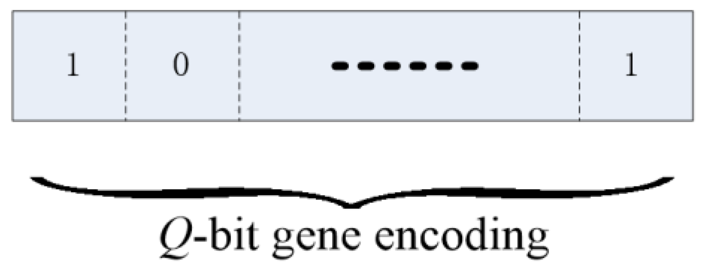
In the application of constant amplitude phased array, only the phase shifter is adjustable, so we assign a constant value to the amplitude of the weighted value of the transmitting unit, and encode the phase in the adjustable range of 360°. Considering the limited quantization limit of phase shifting of the phased array, the optional phase value of each weight can only be a limited quantized phase value pool; for genetic algorithm crossover, mutation and other operations, the value of each emission weight. The phase position in the quantized phase value pool corresponding to the phase is binary coded. Let the number of transmitting units be N, the amplitude be A and the weight value be . Let the number of finite-bit quantization bits of the phased array phase shift be Q, and the pool of quantized phase values be . Let the coding of the phase of the weight of the n-th transmitting unit to be shown in Figure 3:
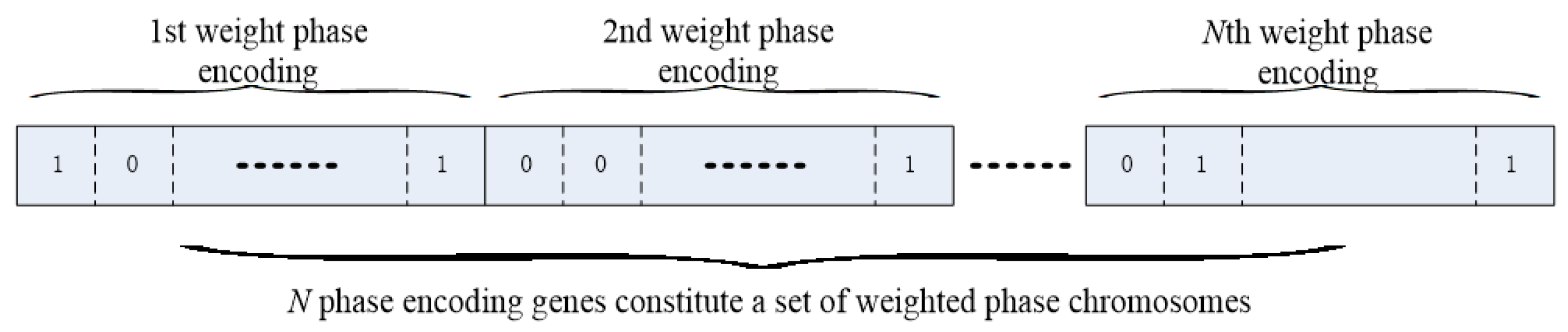
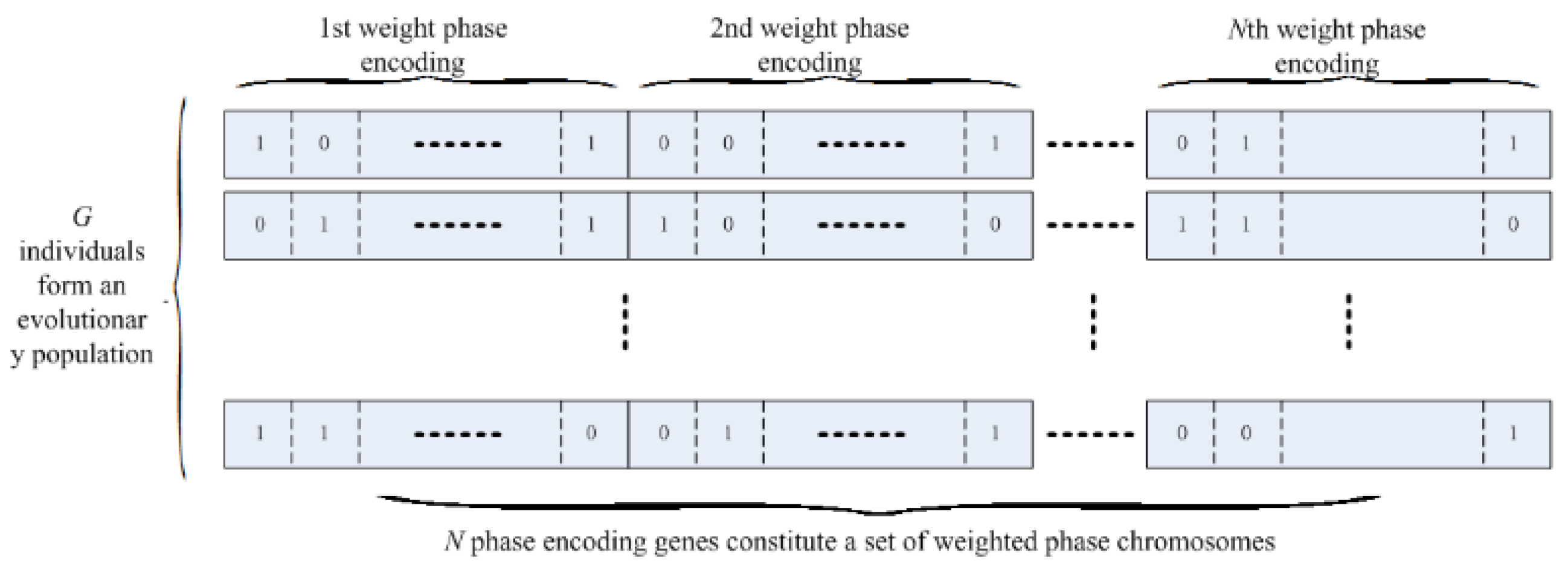
The phase genes of the weights of the N transmitting units constitute a set of weighted phase chromosomes, expressed as in Figure 4:
(2) Population initialization
Assume that each individual processed by the algorithm corresponds to a phase chromosome composed of N phase genes with weights of transmitting units. If there are G individuals in the population, the population is initialized to perform phase chromosomes corresponding to the G individuals and their phase genes with random Q-bit binary encoding, as shown in Figure 5.
(3) Genetic expression
We perform genetic and chromosomal coding of individuals, and after population initialization, through the binary coding of the weight phase of each individual to the phase in the quantized phase value pool, to achieve the conversion of gene coding to weight phase, which is similar to the genetic expression of biological characteristics.
(4) Genetic operations
The genetic operation of this method is mainly aimed at the optimization of the weights of the discrete phases in the self-interference cancellation problem to refine the crossover and mutation mutations, so as to solve the specific problems.
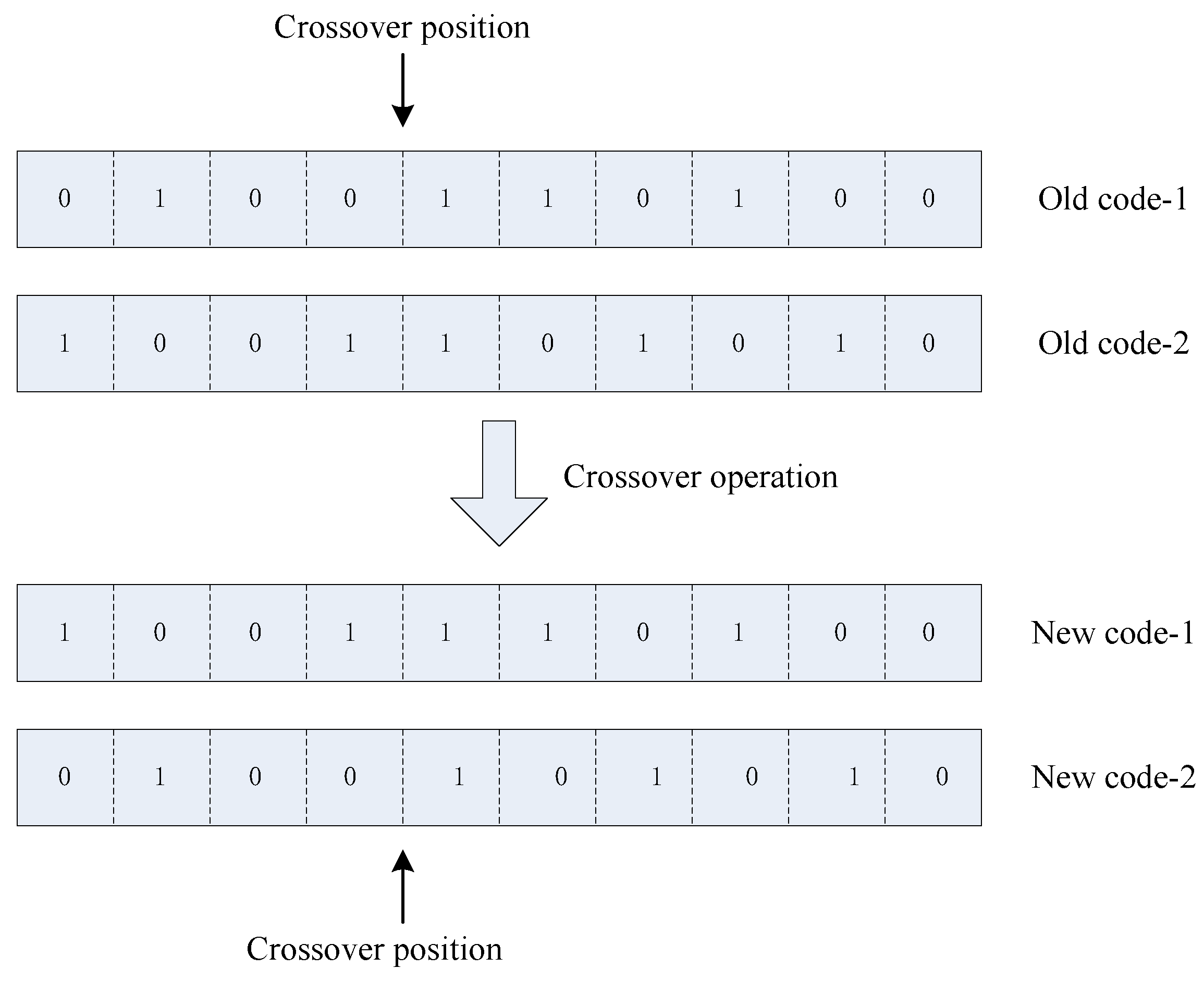
The crossover is performed on the weight phase gene encoding of any two individuals in the evolutionary group. The specific process is to select a cross point in the corresponding Q-bit gene phase encoding of each pair of N emission units in their corresponding Q-bit gene phase coding, and to encode the genes of two individuals in the unit weight with the selected intersection, as shown in the following illustration:
The crossover is carried out for the weight phase encoding of any two individuals in the evolutionary group. The specific processing process is to first select a crossover position in the corresponding Q-bit gene phase encoding of each pair of weight-encoded individuals with the set crossover probability, and then replace the genetic codes of the weights of the two individuals with each other at the selected crossover position, as shown in Figure 6:
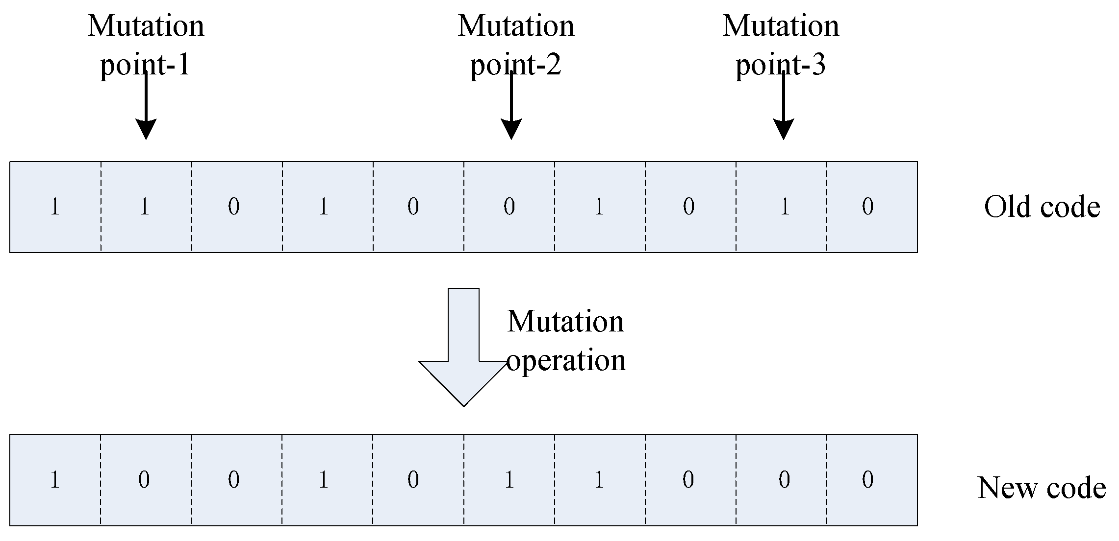
The mutation operation is performed on the weight phase encoding of the individuals in the evolutionary group. The process is to sequentially select the weights of the N transmission units of each individual in the corresponding Q-bit gene phase encoding and select m (m < Q) mutation sites, and perform binary inverse mutation on the gene code of the unit weight at the mutation site as shown in Figure 7:
(5) Fitness assessment
This is a measure of the performance of the evolutionary individual, combined with the actual needs of the problem to be solved, that is, under the constraints of a given beam direction, by controlling only the phase of each weight of the array unit as much as possible to suppress the coupling interference of the transmitting array to the receiving array. It involves the self-interference power of the unit, while ensuring that the formed beam gain loss is minimized and the sidelobe characteristics of the formed transmitting beam are maintained. Therefore, the objective cost function of the individual evolutionary fitness evaluation adopted is:
In this formula, the definition of each parameter is the same as Formula (11).
(6) Elite selection strategy
Population evolution adopts an elite selection strategy. In genetic selection, individuals with the best fitness in each evolutionary generation are preferentially retained, and the corresponding radiation array weight is to ensure that they are not spoiled by genetic operations such as crossover and mutation. The analysis of the mathematical theory based on Markov chain shows that the genetic algorithm adopting the strategy of retaining the optimal individual converges to the optimal solution with probability 1 [18].
(7) Termination of evolution
Set evolutionary generation and fitness evaluation to meet any condition for evolution iteration termination.
Set the maximum evolutionary algebra and fitness evaluation criteria . When the evolutionary algebra exceeds or any condition is met, the evolution is terminated and the optimized transmission array weight is .
3. Electromagnetic Modeling Simulation and Experimental Verification
3.1. Analysis of Self-Interference Characteristics of STAR Array Using Electromagnetic Modeling and Simulation
Based on the self-interference cancellation model and optimization solution method proposed in Section 2, we first construct an electromagnetic model and a digital model for the practical array system, conduct design simulation verification through digital methods and use it for subsequent principle experiment verification and evaluation. In this work, we take the 30(T) × 10(R) array antenna as the example, and study the interference characteristics of two modes, i.e., the separate and the same aperture for transmission and reception.
(1) Separate transmit and receive mode with respective apertures
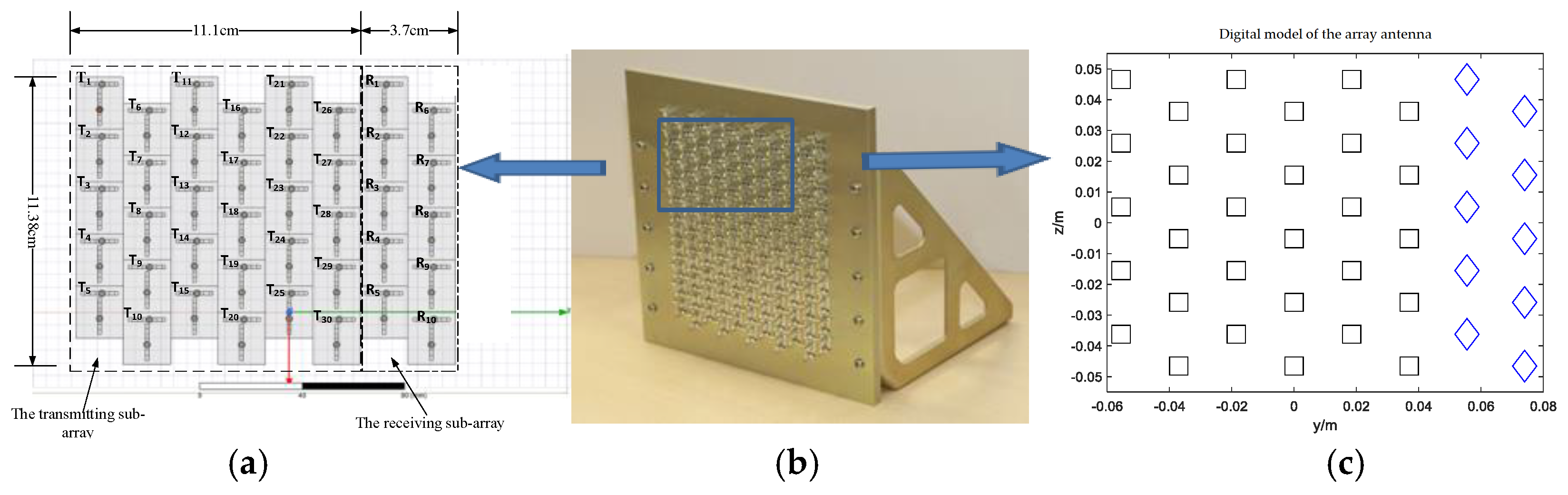
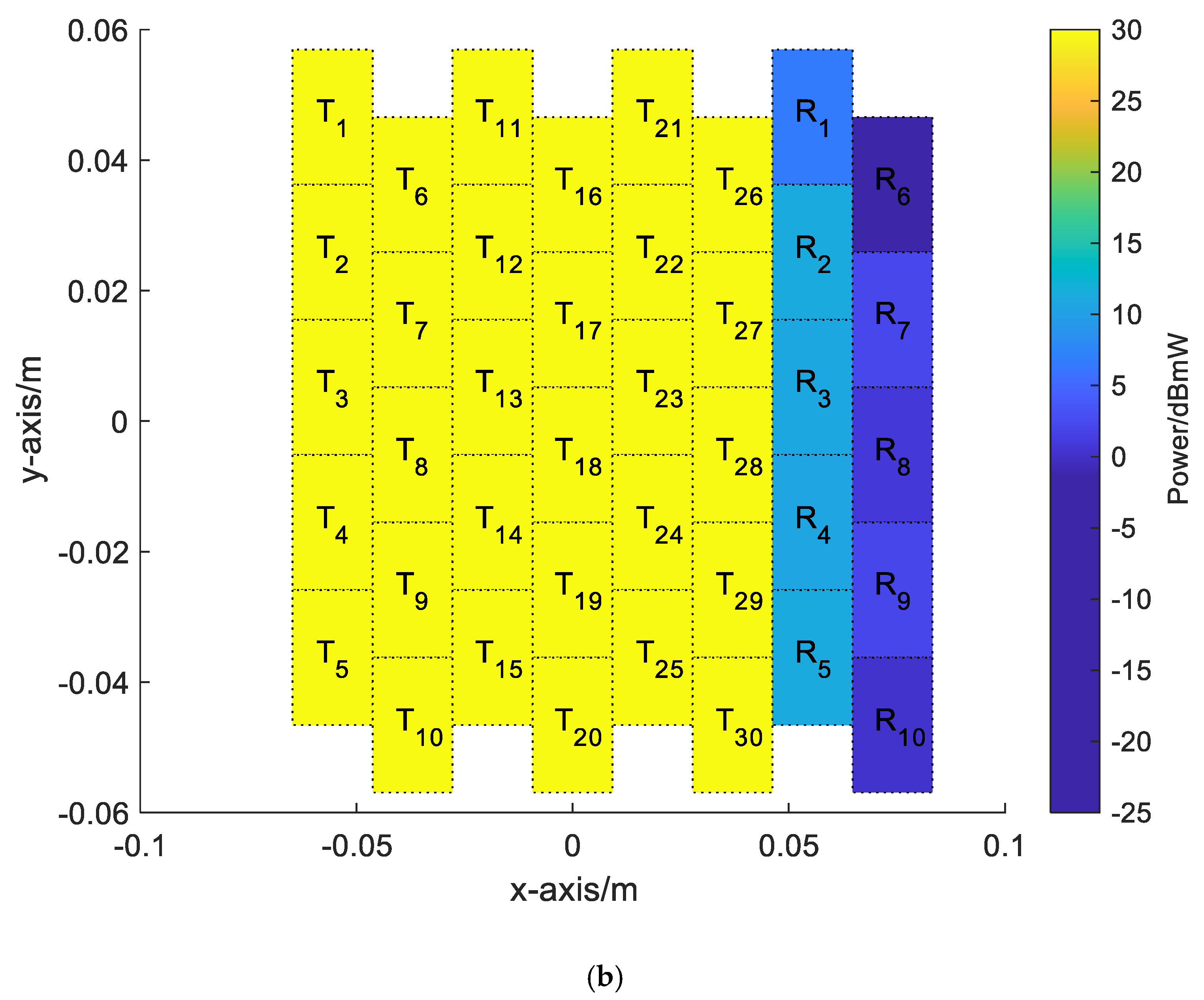
When the separate sub-aperture transmission and reception work simultaneously, the transmission sub-array can be transmitted according to certain beam-shaping weights, and the receiving sub-array can be simultaneously received according to certain receiving beam-shaping weights. The arrangement of the phased array antenna in this mode is shown in Figure 8, and the power of each transmitting component is set to 30 dBm, which can be controlled by the joint weights of amplitude and/or phase.
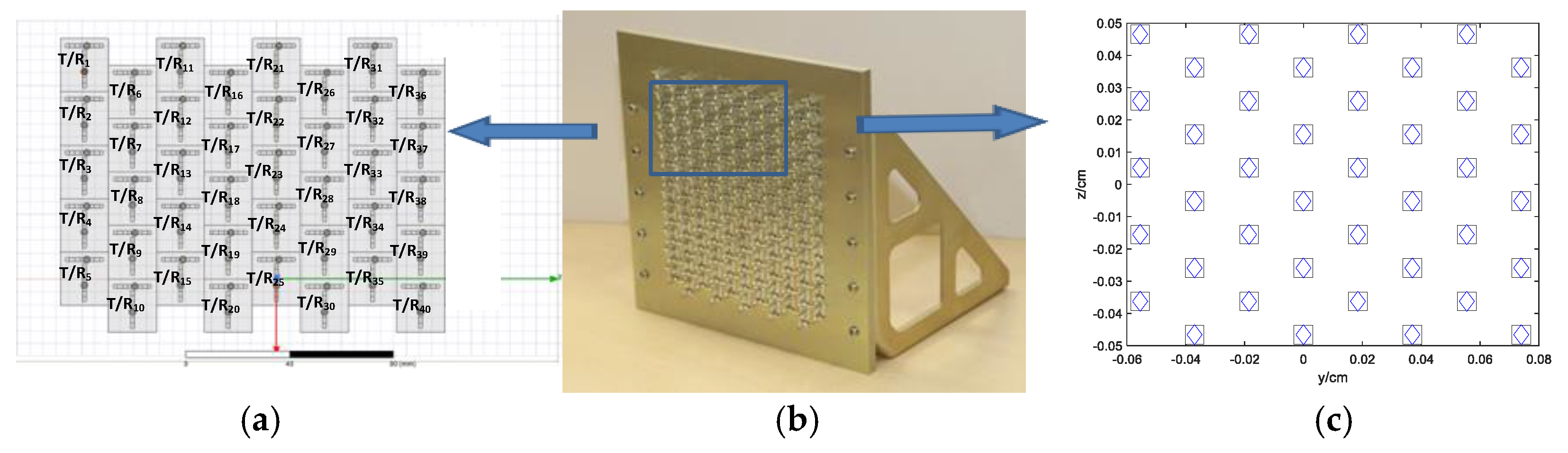
In the research process, combined with the actual physical array antenna development, we design and construct the corresponding electromagnetic model and digital model. Among them, the electromagnetic model is used to electromagnetically analyze the self-interference coupling characteristics between the transmitting and receiving antenna elements. The simulation environment used is Ansoft HFSS. The FEM is used to electromagnetically analyze the coupling characteristics between any two array elements. The parameter of the array is obtained by electromagnetic calculation. Then by choosing the same layout as the specific test array antenna, that is, a transmitting sub-array with 30 units in five rows and six columns and a receiving sub-array with 10 units in five rows and two columns, the parameter of the array is converted to a coupling matrix , as shown in Equation (2). The specific electromagnetic model of the array is shown in Figure 8a. Digital model is that for the practical prototype array antenna, that is, the transmitting sub-array of five rows and six columns, and the receiving sub-array of five rows and two columns, by constructing a digital design simulation model with the same characteristics as the array unit layout and operating frequency. It is used for design simulation to evaluate the beam characteristics and interference suppression performance of the different optimized weights. The simulation environment used by the digital model is Matlab, and the specific digital model legend is shown in Figure 8c. The practical testing array antenna is shown in Figure 8b.
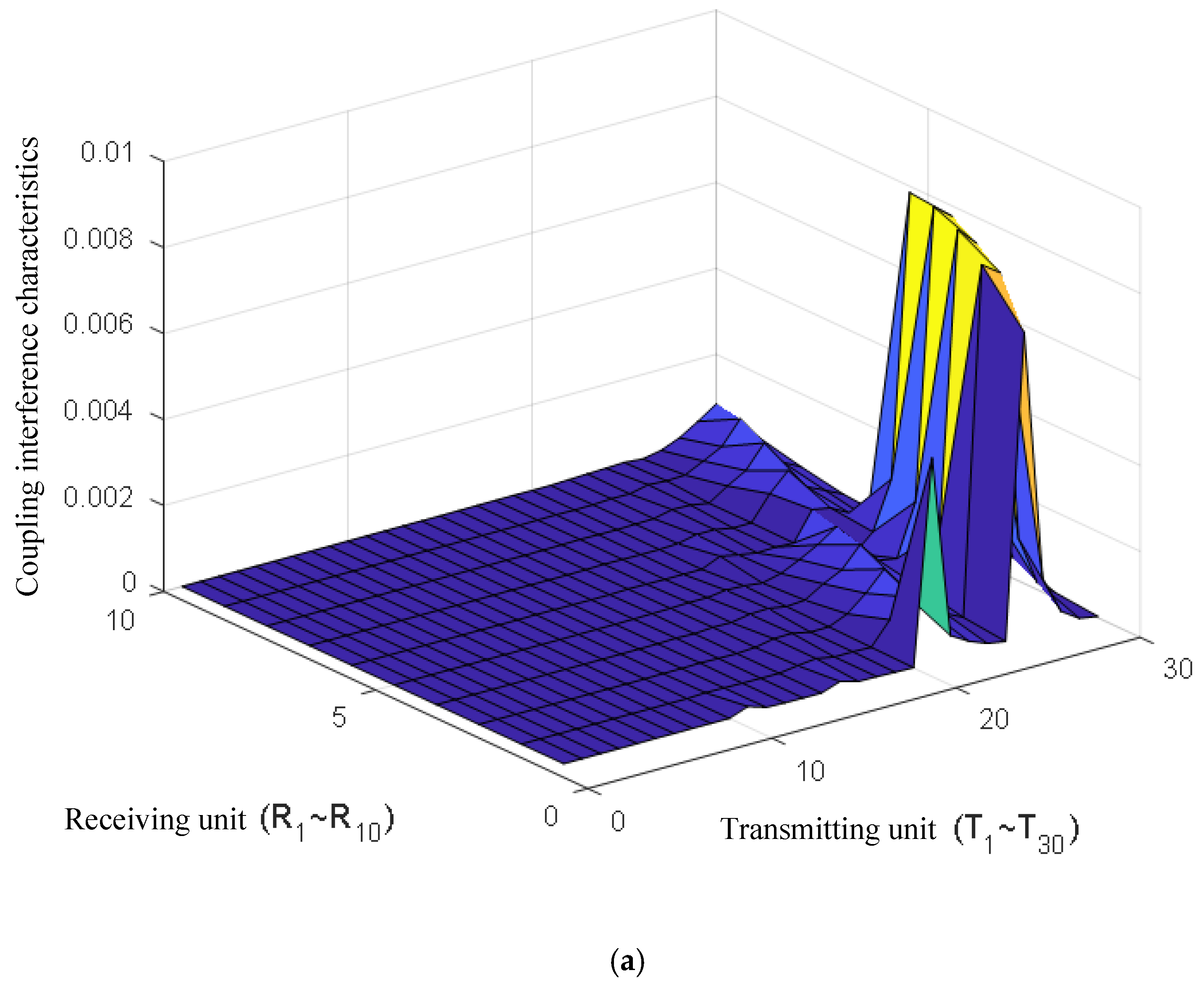
The saturation level of the receiving channel is about −10 dBm; the signal bandwidth is 200 MHz; the receiver noise figure is 3.5 dB; and the corresponding receiver noise floor is about −87.5 dBm. In order to achieve conventional reception operation of the phased array system, the low noise amplifier on the receiving channel of each array element is firstly not saturated, that is, the power of the transmitting signal coupled to each receiving component must be below the saturation level of −10 dBm. By analyzing the self-interference coupling coefficients characteristics of the 30(T) × 10(R) array antenna as shown in Figure 9a, the simulation coupling power at the receiving array elements can be obtained as shown in Figure 9b. It can be seen that for the 30 dBm output power of the transmitting unit, the self-interference power received by the receiving array element is greater than the saturation power of the component by −10 dBm, which exceeds the saturation power of 8.7~21 dBm. As a result, all the receiving components are saturated and cannot receive the desired signal. However, the interference power received by different array elements is greatly different. Therefore, from the SIC demand, the self-interference signal power must be suppressed below the saturation power level of the element to ensure that the component can work normally.
(2) Simultaneous transmit and receive mode with the same aperture
When transmitting and receiving at the same time with the same aperture, all elements of the array work in full-duplex mode. At the time of transmission, each element of the array is transmitted by a given transmit beam-shaping weight to detect the potential target on a given spatial direction; meanwhile, the desired target echo signal is received according to a certain receiving beam-shaping weight.
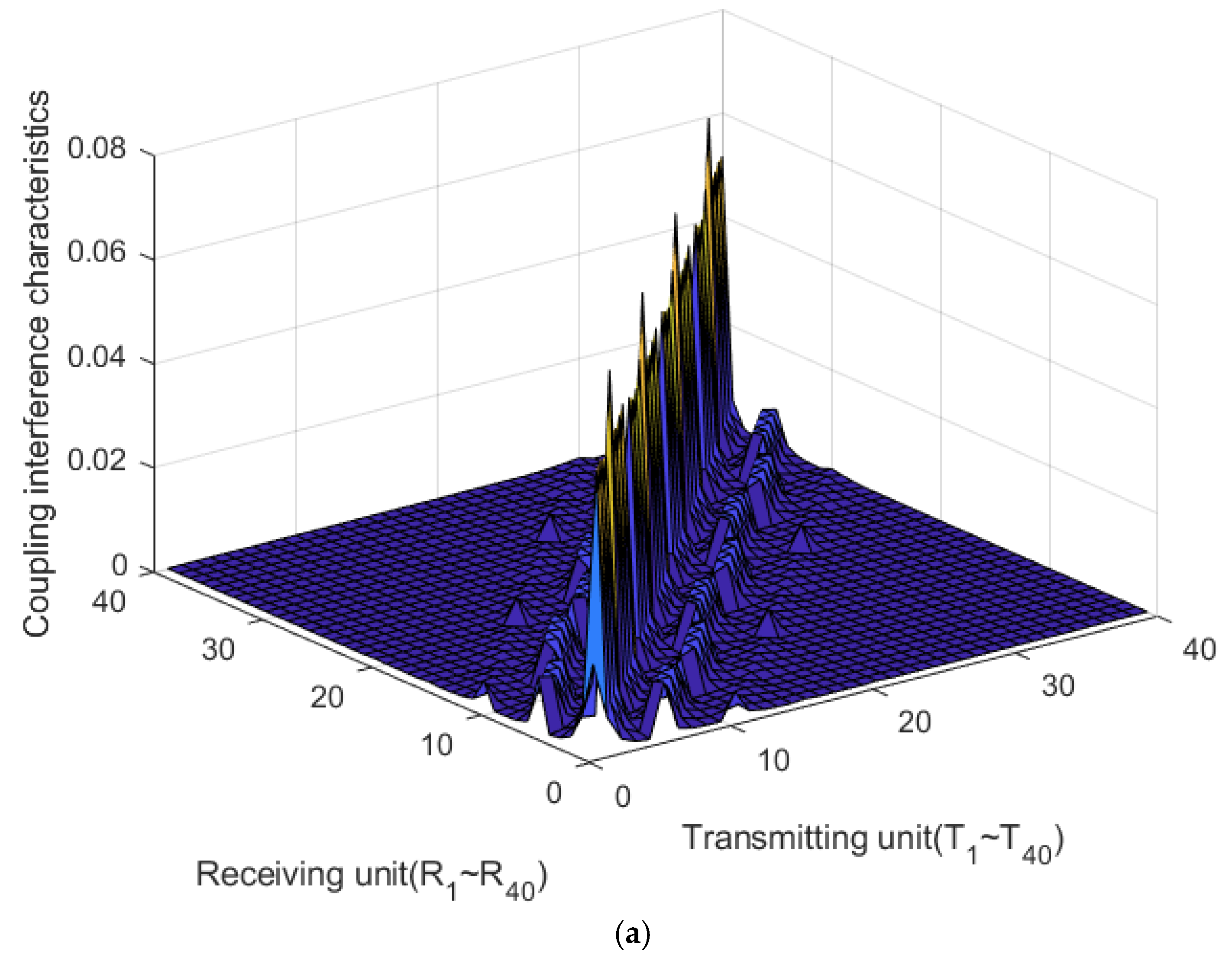
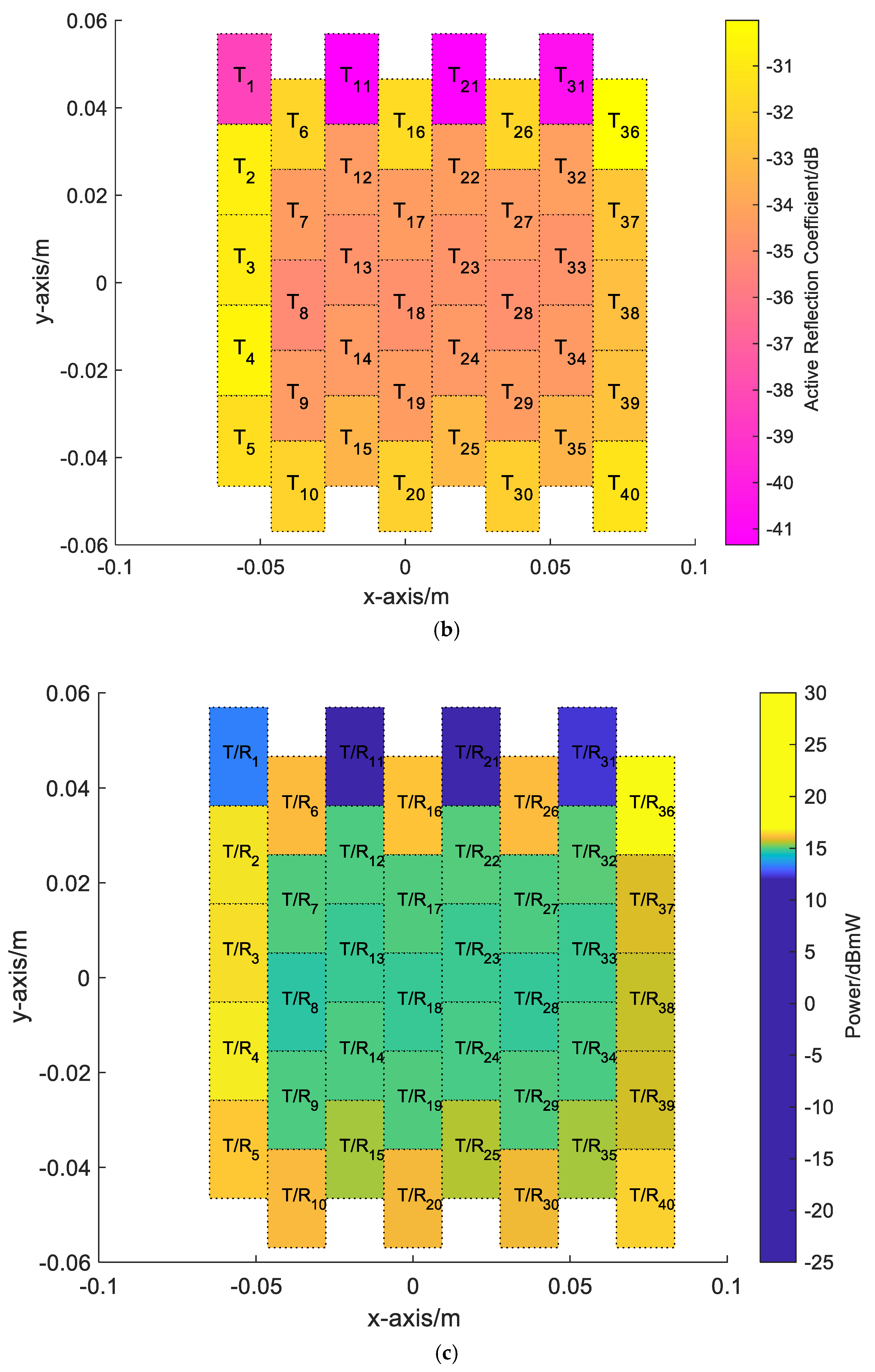
The phased array antenna arrangement in this mode is shown in Figure 10. By analyzing the coupling characteristics of the illustrative array antenna arrangement model shown in Figure 11a, the active reflection coefficients of the array antenna in the same aperture mode can be obtained as shown in Figure 11b. The peak power of each channel is set to 30 dBm, which can be controlled by the joint weight of amplitude and phase. Similarly, the saturation level of the receive component, signal bandwidth, receiver performance and other parameters are the same as the separate-aperture simultaneous transmit and receive mode. From the Figure 11c, it can be derived that for the 30 dBm transmit power at each element, the coupling self-interference power is nearly greater than the receiving saturation power of −10 dBm, and thus all elements will be saturated and unable to receive the desired signal. Furthermore, we can also see that, the coupling interference intensity for the different elements on the array are relatively average, there is no significant difference, and the difficulty in achieving simultaneous transmit and receive for this mode is greater than that in the separate sub-aperture simultaneous transmit and receive mode.
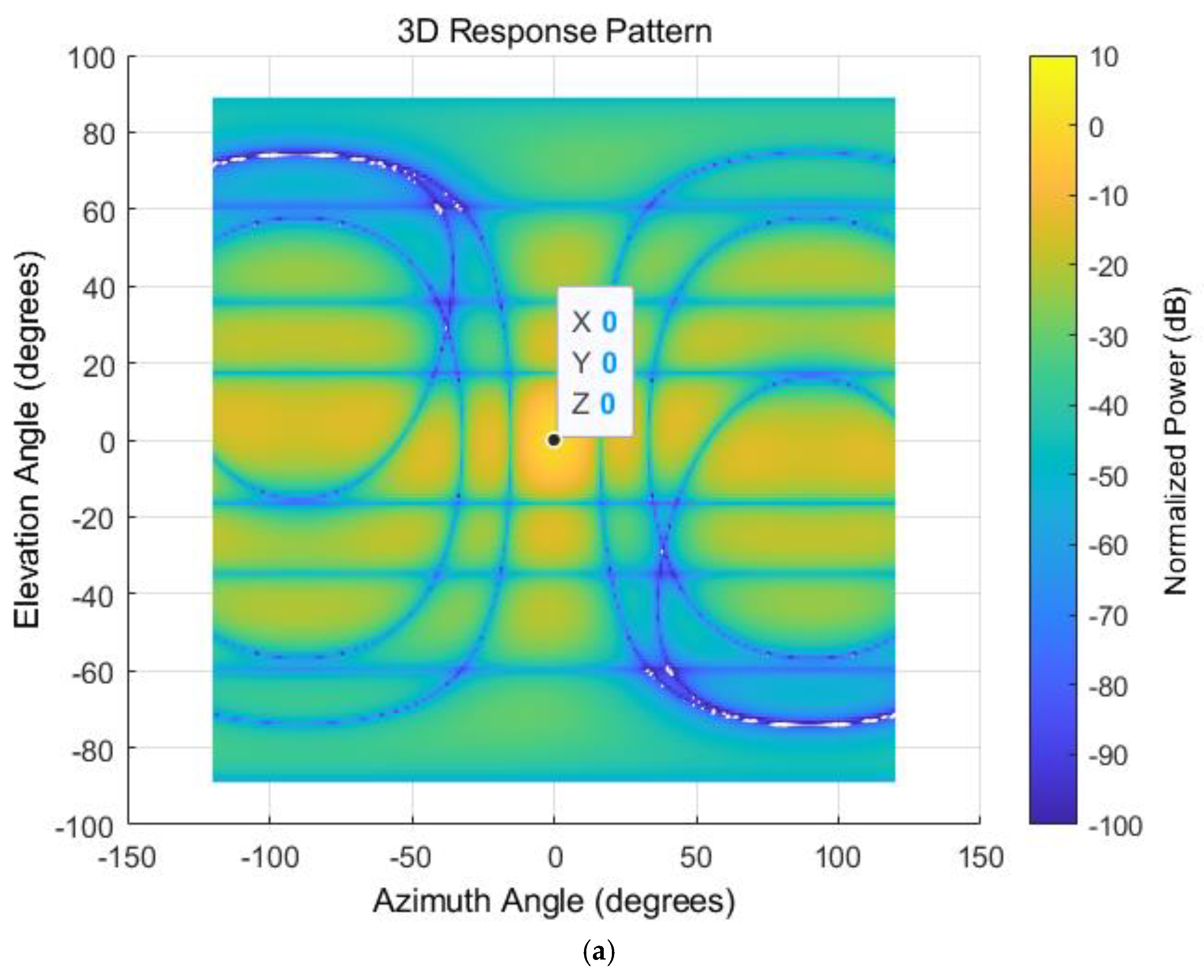
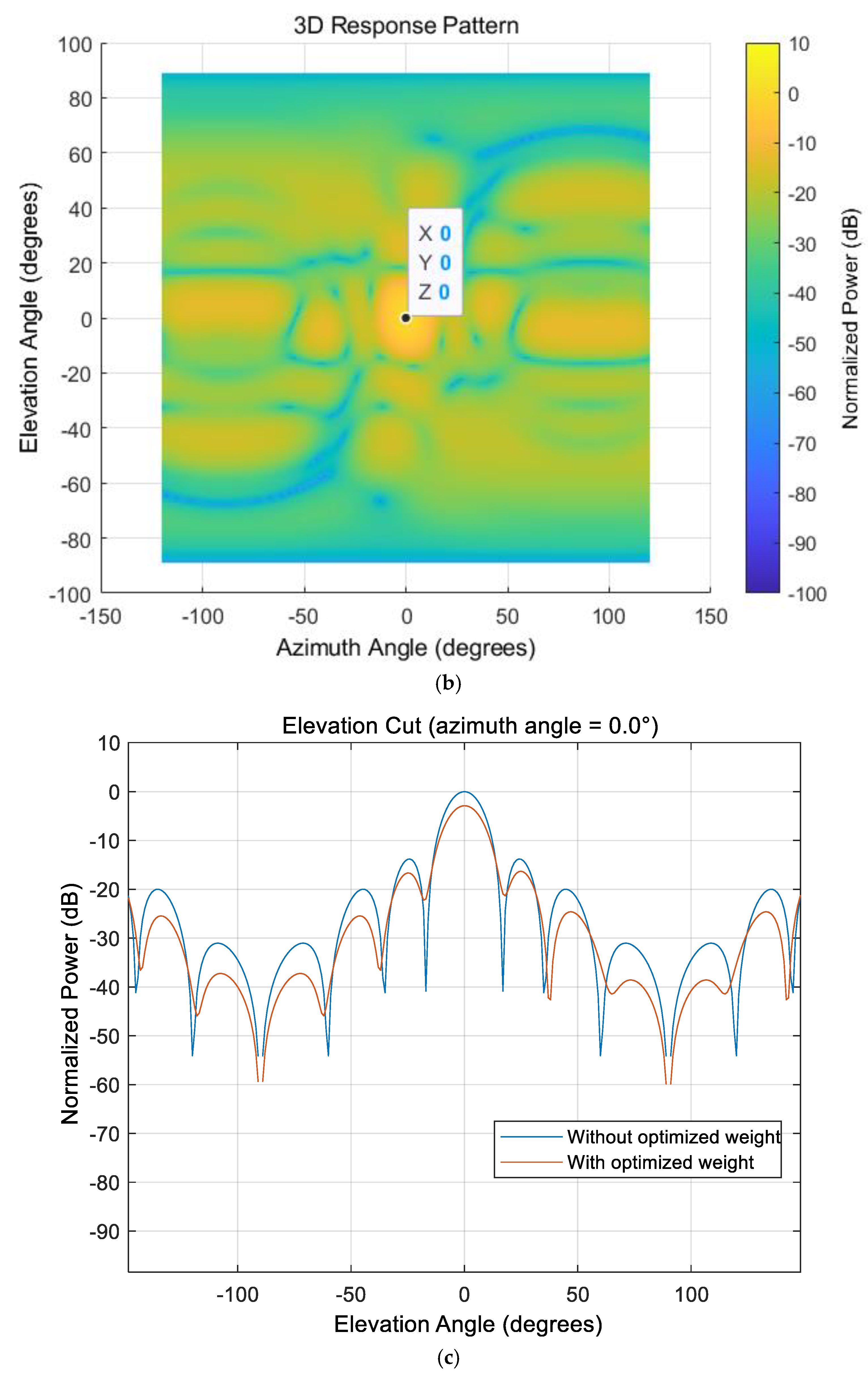
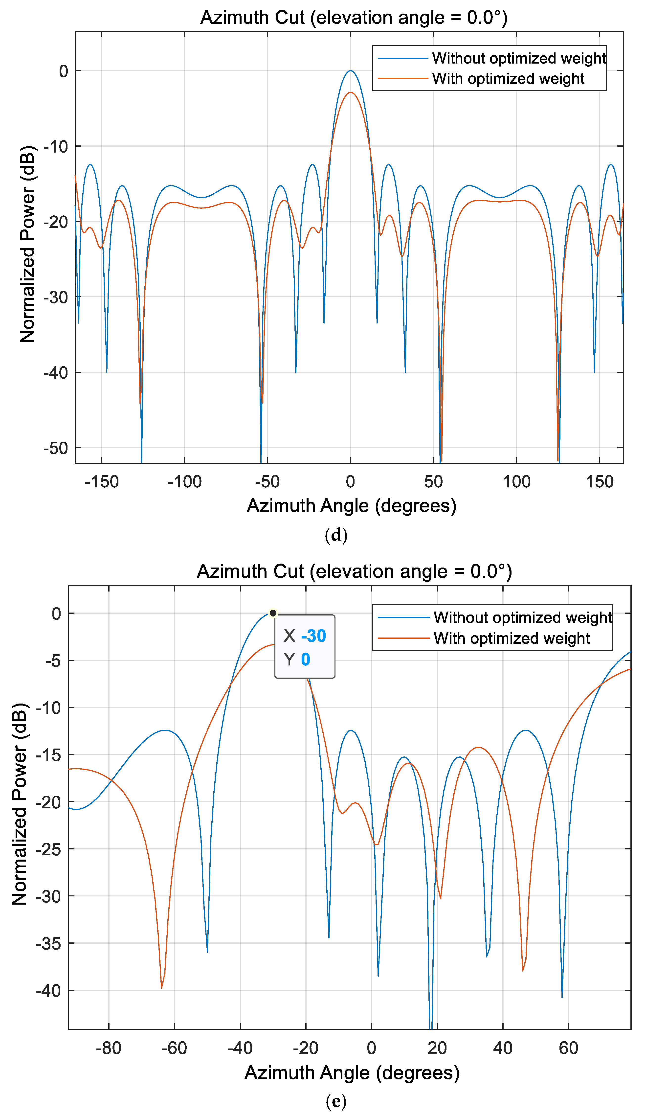
Furthermore, the results of beam characteristics with and without optimized weights are compared in Figure 12, from which we can see that, the optimized weight maintains the beam shape characteristics while keeping the beam pointing unchanged, and the main-sidelobe ratio does not change significantly.
In summary, it can be seen that when the phased array system is transmitting and receiving at the same time, the self-interferences power generated in both modes is significantly higher than the saturation power level of the receiving channel, which seriously affect the normal receiving function of the components of the phased array system. For the cancellation demand, the self-interference must first be suppressed to below the receiving saturation power to ensure that the component can work normally. Secondly, after the received signal normally passes through the receiving channel, the interference needs to be further suppressed to or below the receiver noise floor level before the signal processing. Lower than the noise level can ensure the normal operation of the system without affecting the processing functions of the system.
3.2. Experimental Verification of Self-Interference Suppression of Simultaneous Transmission and Reception of the Array
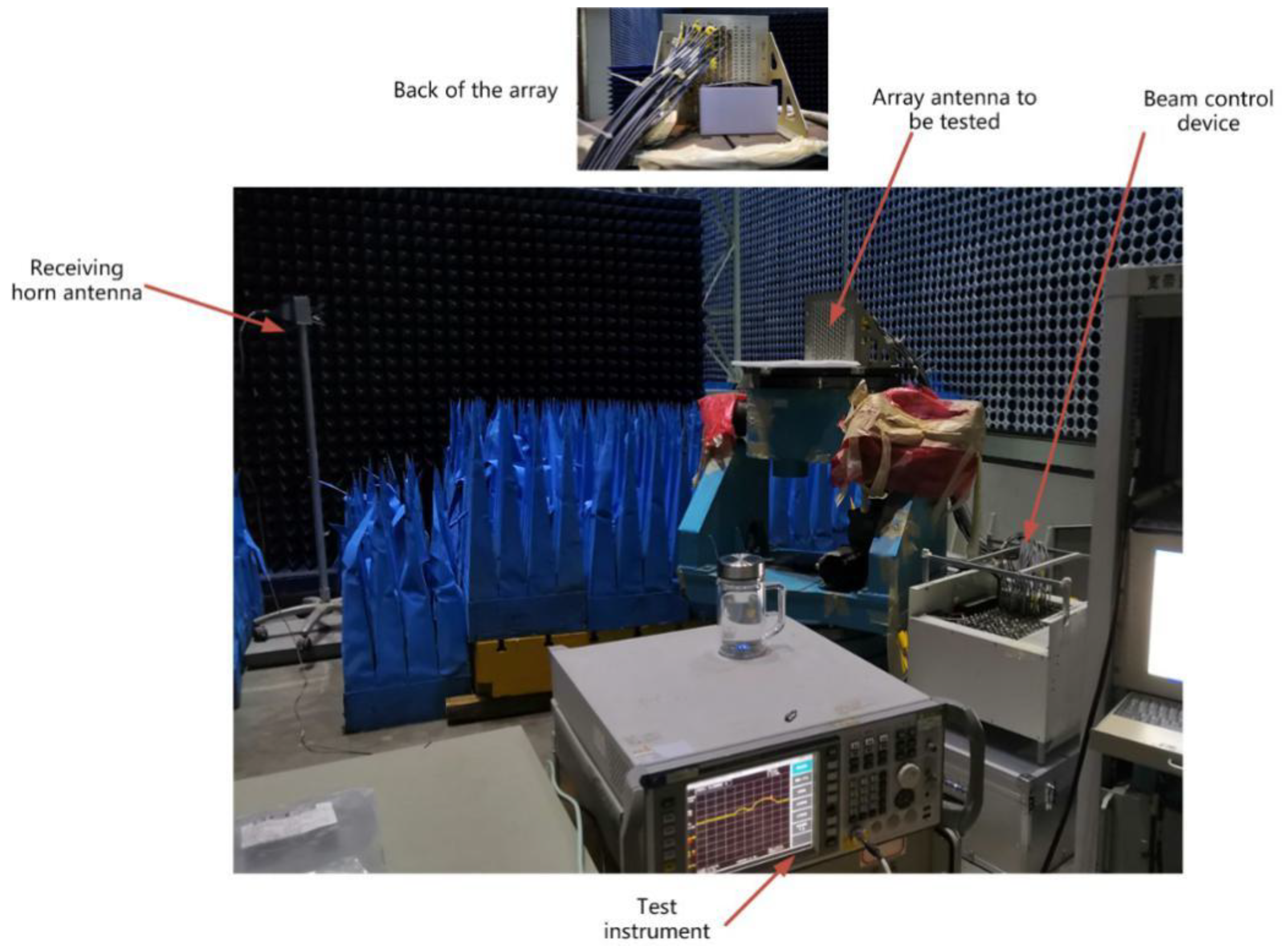
On the basis of simulation, we conducted experimental verification through the actual array antenna. In view of the actual array situation, we choose 30 units to transmit and 10 units to receive, as shown in Figure 8, while taking into account the limitations of the actual array system with 6-bit finite phase quantization, that is, the phase quantization step size of 5.625°. Then the scenario and results are shown in Figure 13, Figure 14 and Figure 15:
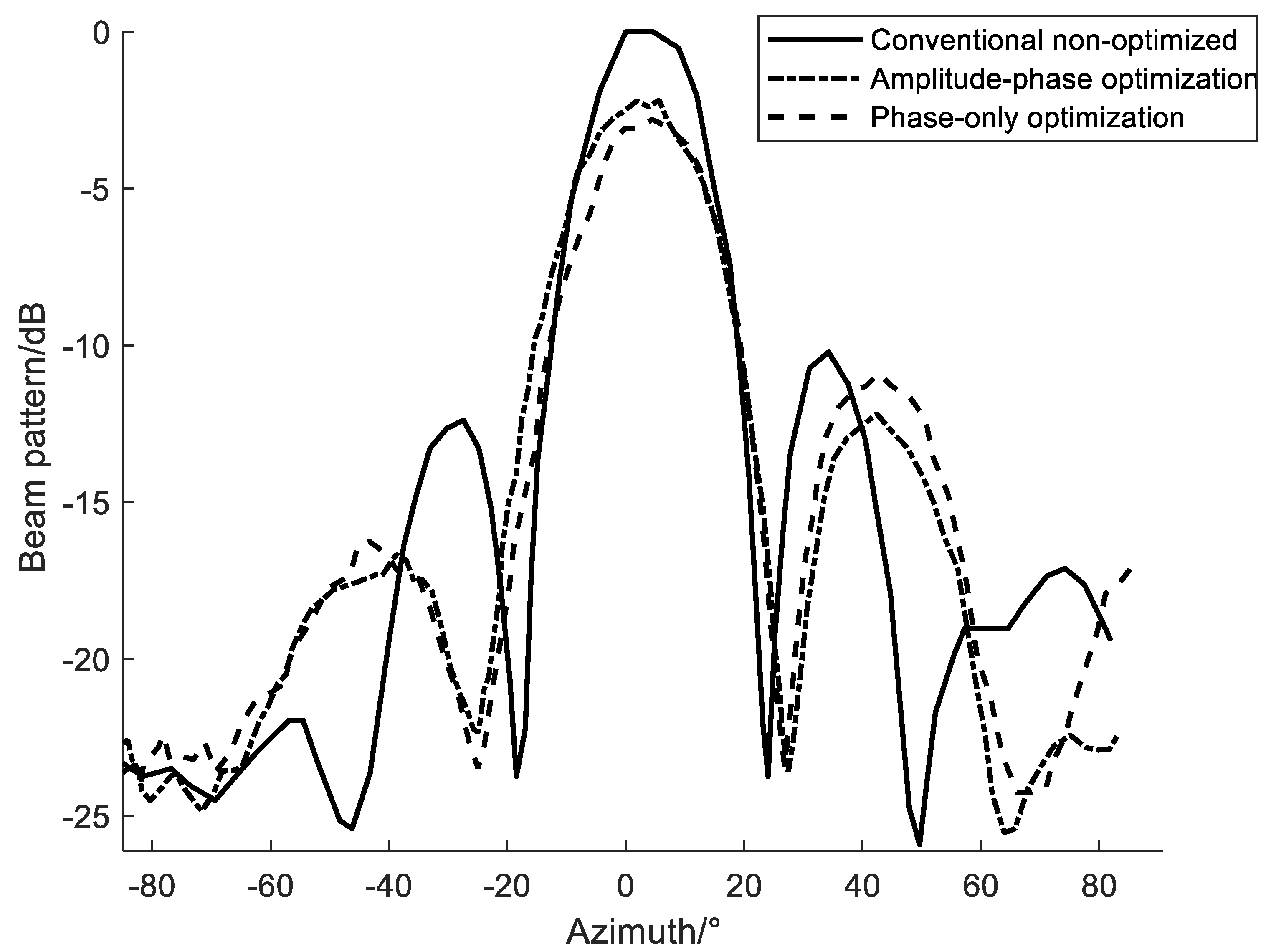
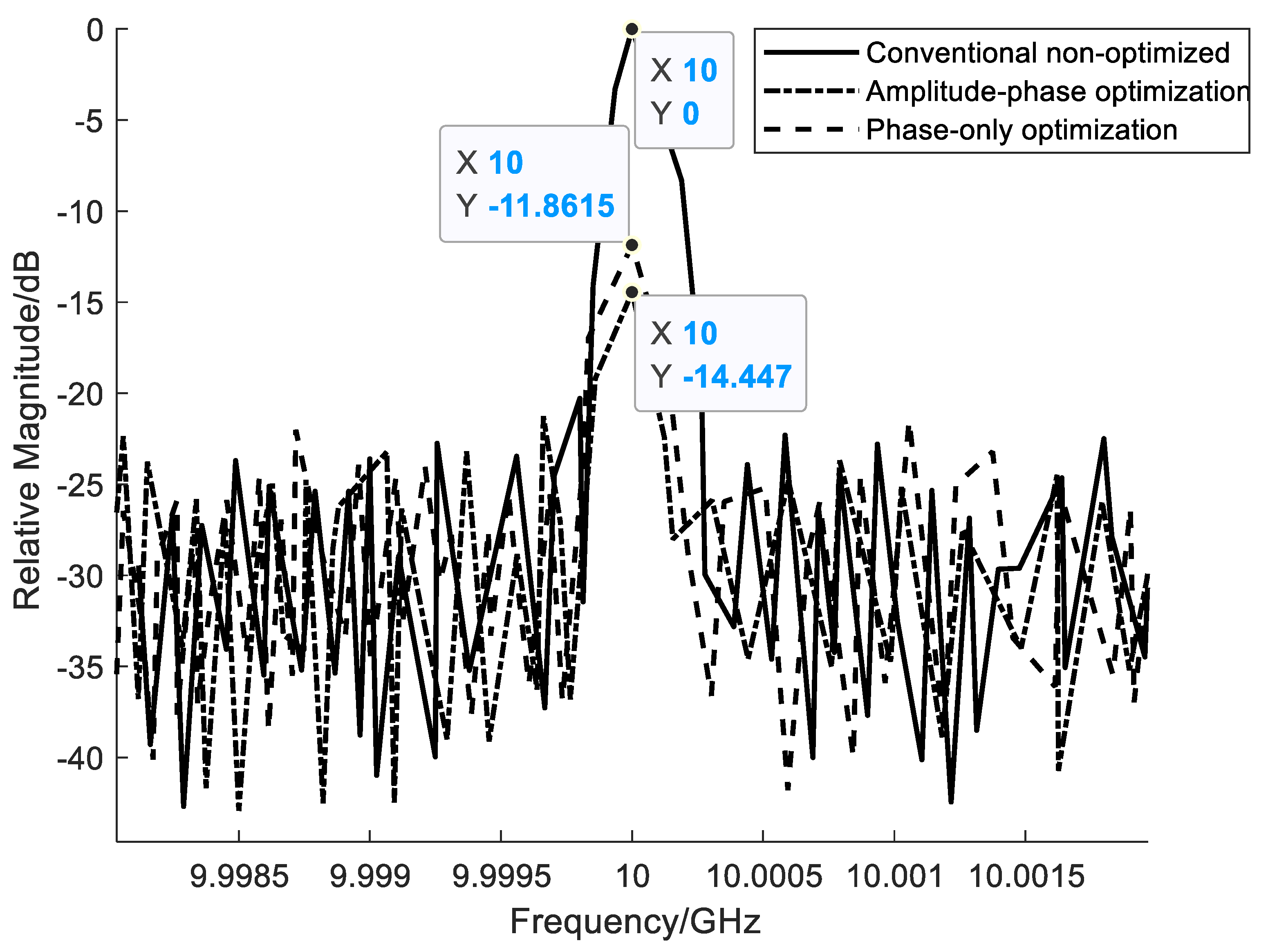
Based on the test results shown in Figure 14 and Figure 15, it can be seen that the self-interference suppression method using only phase control weights with limited number of digits and conventional amplitude-phase joint control weights can better eliminate the coupled self-interference in the array system, around 11.9 dB~14.4 dB; and at the same time it maintains a certain beam shape and beam directivity, but the optimized beam gain has a certain loss, about 2~3 dB. Simultaneously, we can also see that the optimization result of only the phase control weight is slightly worse than the optimization result of the amplitude-phase joint control weight, including interference suppression and beam shape maintenance. The results of these experiments are basically consistent with the trend of the simulation results as shown in Figure 9, indicating the rationality of the established interference suppression model and its solution method.
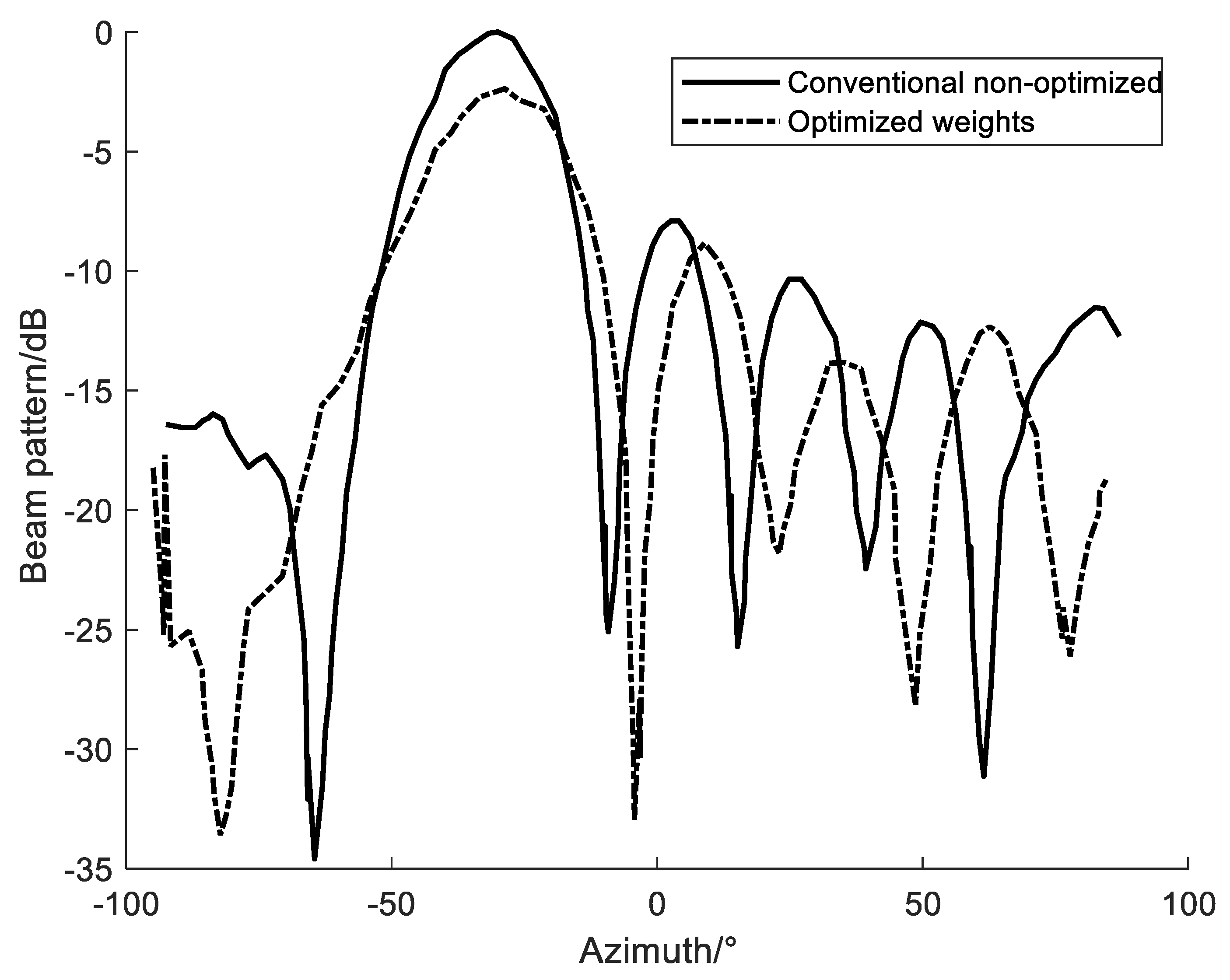
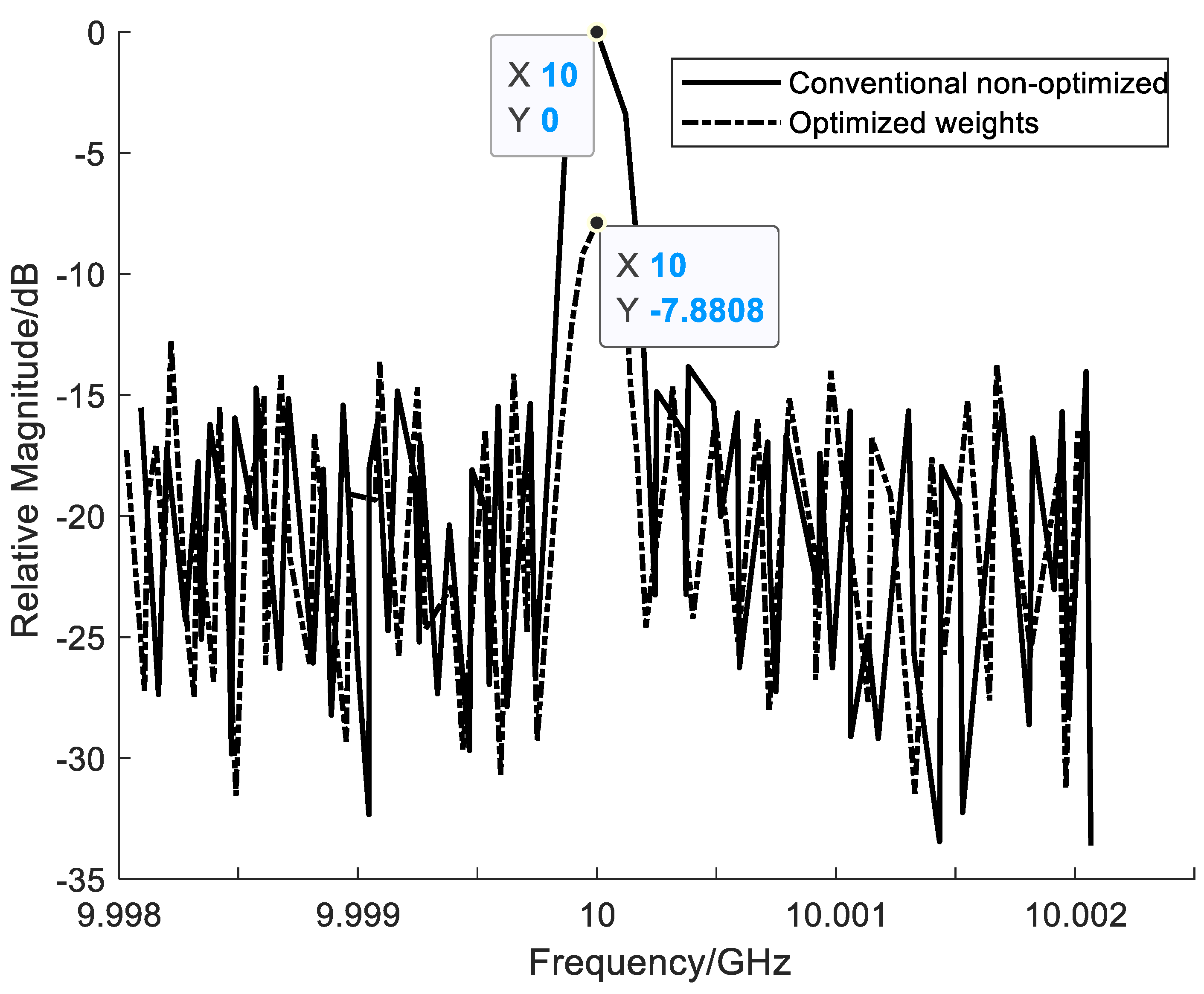
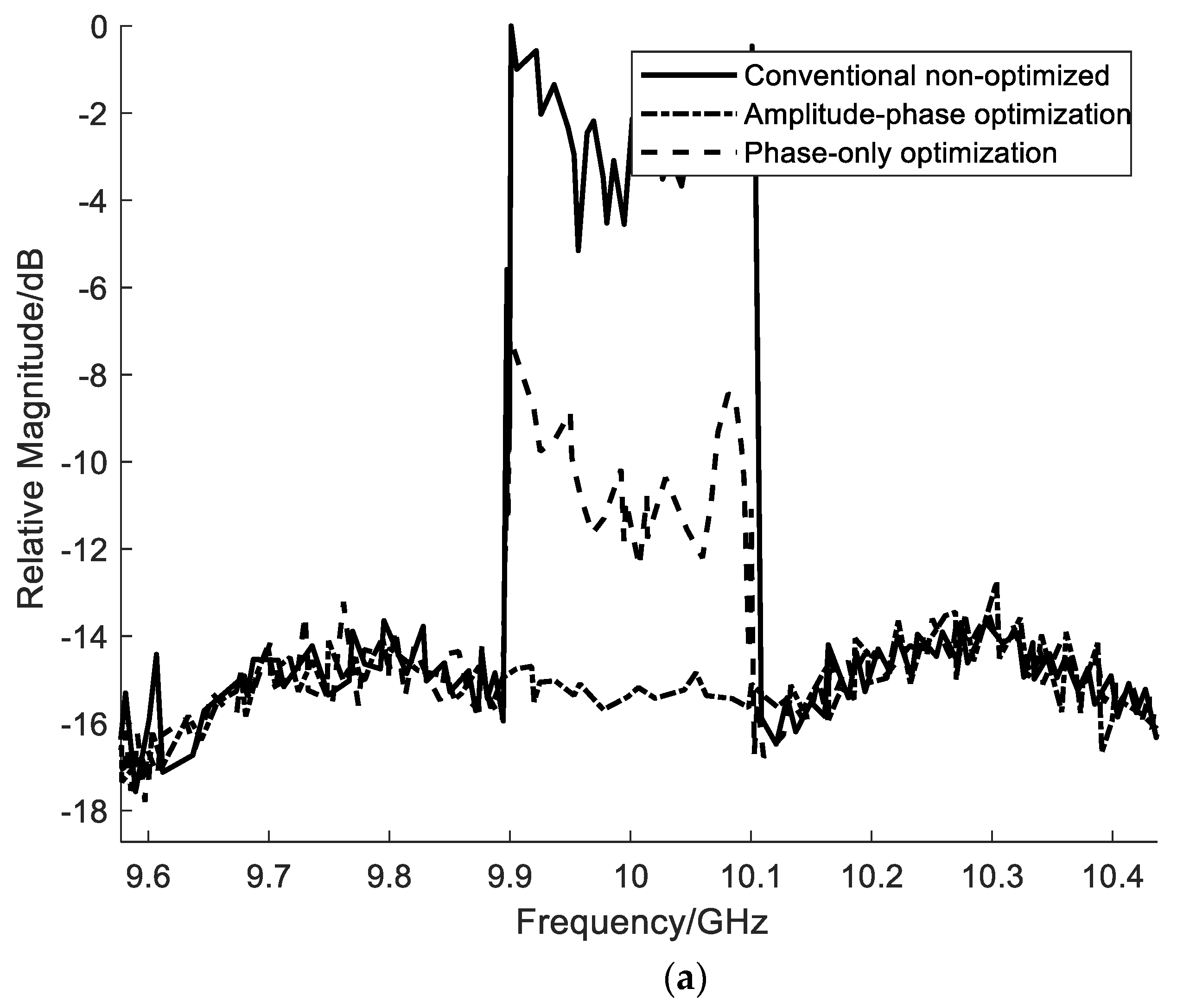
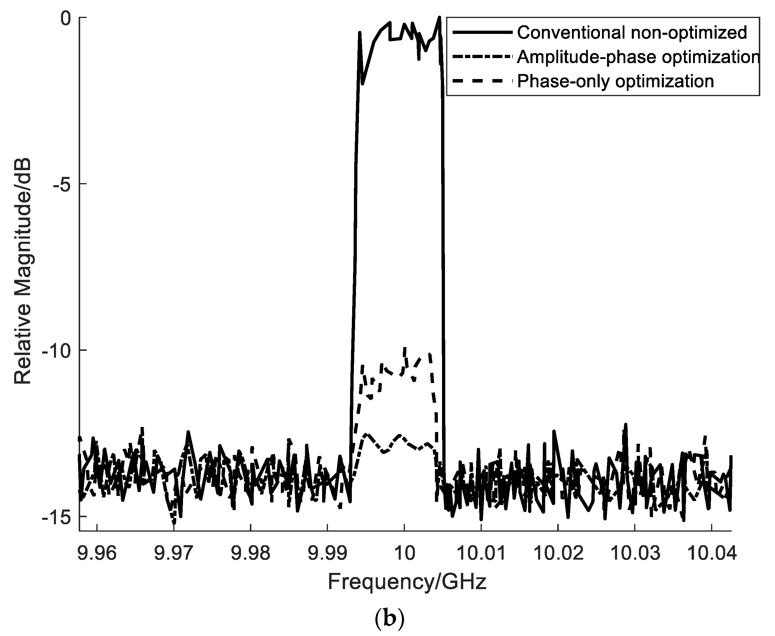
In addition, we also studied the performance of interference suppression and beam shape retention in the case of phased array scanning. As shown in Figure 16 and Figure 17, when the azimuth scan angle is −30 degrees and the elevation scan angle is 0 degrees, the weights optimized by the amplitude-phase joint optimization can also suppress the coupling self-interference to a certain extent. In our experiments, the interference suppression of the transmitting beam is about 7.88 dB, which is slightly worse than the situation when the beam is pointing in the (0°,0°) direction. The reason for this situation should be that with the beam scanning, the coupling characteristics between array units have changed, and the coupling matrix derived from the S21 parameters obtained by the electromagnetic calculation between the array units based only on static array cannot strictly and accurately represent the coupling characteristics in the case of array scanning [21]. It is also noted from the results of beam characteristics that it maintains relatively consistent beam pointing and beam shape, and the relative gain loss (2.44 dB) does not change significantly. However, the absolute gain loss increases as the scanning angle changes, which should be the basic phenomenon of array scanning. In addition, we applied this method to the self-interference suppression of wideband signals, and it also achieved comparable suppression performance for 200 MHz and 10 MHz wideband signals, as shown in Figure 18. It can be seen from the results of the cancellation experiment that the weights calculated by the method in the article can achieve the self-interference suppression of the wideband signal in the transmission domain. However, as the bandwidth increases, due to the increase in signal frequency difference and large changes in coupling characteristics [3], the interference suppression performance at the edge of the wideband signal decreases. Take 200 MHz wideband signal as an example, the joint amplitude and phase optimization method and the phase-only method are used. The interference suppression performance can reach about 13.83 dB and 8.73 dB, respectively, which effectively suppresses the wideband self-interference signals.
4. Conclusions
To sum up, aiming at the practical application of FD technology in phased array, we propose the principle model and corresponding optimization methods for some practical limiting factors such as limited quantization number, constant envelope amplitude, scanning mode and wideband signal mode. The feasibility of the optimization methods has been verified by simulation and principle experiments. For the future work, we need to consider the further optimization of the algorithm and the fine step of the weight quantization in the actual physical implementation.
Author Contributions
Conceptualization, J.Z. (Jie Zhang); methodology, J.Z. (Jie Zhang); software, J.Z. (Jie Zhang); validation, J.Z. (Jie Zhang) and J.Z. (Jiudong Zheng); writing—original draft preparation, J.Z. (Jie Zhang); writing—review and editing, J.Z. (Jie Zhang); visualization, J.Z. (Jie Zhang). All authors have read and agreed to the published version of the manuscript.
Funding
This research received no external funding.
Institutional Review Board Statement
Not applicable.
Informed Consent Statement
Not applicable.
Data Availability Statement
Not applicable.
Conflicts of Interest
The authors declare no conflict of interest.
References
- Bharadia, D.; McMilin, E.; Katti, S. Full Duplex Radios. In Proceedings of the ACM SIGCOMM, Hong Kong, China, 12–16 August 2013. [Google Scholar]
- Choi, J.I.; Jain, M.; Srinivasan, K.; Levis, P.; Katti, S. Achieving Single Channel, Full Duplex Wireless Communications. In Proceedings of the Sixteenth Annual International Conference on Mobile Computing and Networking, Chicago, IL, USA, 20–24 September 2010. [Google Scholar]
- Li, M.; Chen, X.; Zhang, A.; Kishk, A.A.; Fan, W. Reducing Correlation in Compact Arrays by Adjusting Near-Field Phase Distribution for MIMO Applications. IEEE Trans. Veh. Technol. 2021, 70, 7885–7896. [Google Scholar] [CrossRef]
- Da, Y.; Zhang, Z.; Chen, X.; Kishk, A. Mutual Coupling Reduction with Dielectric Superstrate for Base Station Arrays. IEEE Antennas Wirel. Propag. Lett. 2021, 20, 843–847. [Google Scholar] [CrossRef]
- Li, M.; Chen, X.; Zhang, A.; Fan, W.; Kishk, A.A. Split Ring Resonator Loaded Baffles for Decoupling of Dual-polarized Base Station Array. IEEE Antennas Wirel. Propag. Lett. 2020, 19, 1828–1832. [Google Scholar] [CrossRef]
- Zhang, J.; Li, S.; Chang, W.; Jiang, T.; Li, B.; Liang, Z. Study on Full-Duplex Channel Characteristic for Simultaneous Transmit and Receive Used in Phased Array. In Proceedings of the 2019 IEEE International Symposium on Antennas and Propagation and USNC-URSI Radio Science Meeting, Atlanta, GA, USA, 7–12 July 2019. [Google Scholar]
- Everett, E. SoftNull Many-Antenna Full-Duplex Wireless via Digital Beamforming. IEEE Trans. Wirel. Commun. 2016, 15, 8077–8092. [Google Scholar] [CrossRef]
- Doane, J.P. Simultaneous Transmit and Receive with Digital Phased Arrays. In Proceedings of the IEEE International Symposium on Phased Array Systems and Technology (PAST), Waltham, MA, USA, 18–21 October 2016; pp. 1–6. [Google Scholar]
- Liu, X.; Xiao, Z.; Bai, L.; Choi, J.; Xia, P.; Xia, X.G. Beamforming Based Full-Duplex for Millimeter-Wave Communication. Sensors 2016, 16, 1130. [Google Scholar] [CrossRef] [PubMed]
- Xiao, Z.; Xia, P.; Xia, X. Full-duplex Millimeter-wave Communication. IEEE Wirel. Commun. 2017, 24, 136–143. [Google Scholar] [CrossRef] [Green Version]
- Cummings, I.T.; Schulz, T.J.; Doane, J.P.; Havens, T.C. An Information-theoretic Approach to Partitioning Simultaneous Transmit and Receive Digital Phased Arrays. In Proceedings of the 2018 IEEE Radar Conference, Oklahoma City, OK, USA, 23–27 April 2018. [Google Scholar]
- Cummings, I.T.; Schulz, T.J.; Havens, T.C.; Doane, J.P. Optimizing the Information-theoretic Partitioning of Simultaneous Transmit and Receive Phased Arrays. In Proceedings of the 2018 IEEE International Symposium on Antennas and Propagation, Boston, MA, USA, 8–13 July 2018. [Google Scholar]
- Fenn, A.J. Evaluation of Adaptive Phased Array Antenna, Far-field Nulling Performance in the Near-field Region. IEEE Trans. Antennas Propag. 1990, 38, 173–185. [Google Scholar] [CrossRef]
- Yaghjian, A.D. An Overview of Near-field Antenna Measurements. IEEE Trans. Antennas Propag. 1986, 34, 30–45. [Google Scholar] [CrossRef] [Green Version]
- Sayers, A.; Dorsey, W.; O’Haver, K.; Valenzi, J. Planar Near-field Measurement of Digital Phased Arrays Using Near-field Scan Plane Reconstruction. IEEE Trans. Antennas Propag. 2012, 60, 2711–2718. [Google Scholar] [CrossRef]
- Liao, Y.P.; Han, H.; Guo, Q. Design of Robust Near-field Multi-beam Forming Based on Improved LCMV Algorithm. J. Inf. Hiding Multimed. Signal Process. 2015, 6, 783–791. [Google Scholar]
- Lin, J.R.; Peng, Q.C.; Shao, H.Z. Near-field Robust Adaptive Beamforming Based on Worst-case Performance Optimization. Int. J. Comput. Electr. Eng. 2006, 1, 712–718. [Google Scholar]
- Yan, P.; Zhang, C. Artificial Neural Network and Simulated Evolutionary Computation; Tsinghua University Press: Beijing, China, 2000; pp. 396–415. [Google Scholar]
- Bharadia, D.; Katti, S. Full duplex MIMO radios. In Proceedings of the 11th USENIX Conference on Networked Systems Design and Implementation (NSDI’14), Seattle, WA, USA, 2–4 April 2014; USENIX Association: Berkeley, CA, USA, 2014; pp. 359–372. [Google Scholar]
- Zhang, Z.; Long, K.; Vasilakos, A.V.; Hanzo, L. Full-Duplex Wireless Communications: Challenges, Solutions, and Future Research Directions. Proc. IEEE 2016, 104, 1369–1409. [Google Scholar] [CrossRef] [Green Version]
- Riihonen, T.; Werner, S.; Wichman, R. Mitigation of loopback self-interference in full-duplex MIMO relays. IEEE Trans. Signal Process. 2011, 59, 5983–5993. [Google Scholar] [CrossRef]
- Haupt, R.L.; Werner, D.H. Genetic Algorithms in Electromagnetics; Wiley-Interscience: Hoboken, NJ, USA, 2007. [Google Scholar]
- Cummings, I.T.; Doane, J.P.; Schulz, T.J.; Havens, T.C. Aperture-Level Simultaneous Transmit and Receive with Digital Phased Arrays. IEEE Trans. Signal Process. 2020, 68, 1243–1258. [Google Scholar] [CrossRef]
- Zhang, J.; Zheng, J.; Chang, W. Research on The Effect of Phased Array Beam Scanning on Self-interference Cancellation. In Proceedings of the 2020 IEEE Radar Conference (RadarConf20), Florence, Italy, 21–25 September 2020. [Google Scholar]
- Gerber, D.L. Adaptive Transmit Beamforming for Simultaneous Transmit and Receive. Master’s Thesis, Massachusetts Institute of Technology, Cambridge, MA, USA, 2011. [Google Scholar]
- Shah, M.; Cheema, H.M.; Abbasi, Q.H. Substrate Integrated Waveguide Antenna System for 5G In-Band Full Duplex Applications. Electronics 2021, 10, 2456. [Google Scholar] [CrossRef]
- Liu, B.; Chen, X.; Tang, J.; Zhang, A.; Kishk, A. Co- and cross-polarization decoupling structure with polarization rotation property between linearly polarized dipole antennas with application to decoupling of circularly polarized antennas. IEEE Trans. Antennas Propag. 2021, in press. [Google Scholar] [CrossRef]
- Wang, Y.; Chen, X.; Liu, X.; Yi, J.; Chen, J.; Zhang, A.; Kishk, A.A. Improvement of diversity and capacity of MIMO system using scatterer array. IEEE Trans. Antennas Propag. 2021, in press. [Google Scholar] [CrossRef]
- Aryafar, E.; Keshavarz-Haddad, A. PAFD: Phased Array Full-Duplex. In Proceedings of the IEEE INFOCOM 2018—IEEE Conference on Computer Communications, Honolulu, HI, USA, 16–19 April 2018. [Google Scholar]
- Kolodziej, K.E.; Doane, J.P.; Perry, B.T.; Herd, J.S. Adaptive Beamforming for Multi-Function In-Band Full-Duplex Applications. IEEE Wirel. Commun. 2021, 28, 28–35. [Google Scholar] [CrossRef]
- Golub, G.H.; van Loan, C.F. Matrix Computations, 3rd ed.; Johns-Hopkins University Press: Baltimore, MD, USA, 1996. [Google Scholar]
- Available online: https://people.math.osu.edu/costin.10/5102/Rayleigh%20quotient.pdf (accessed on 20 August 2021).
- Kolodziej, K.E.; McMichael, J.G.; Perry, B.T. Multitap RF Canceller for In-Band Full-Duplex Wireless Communications. IEEE Trans. Wirel. Commun. 2016, 15, 4321–4334. [Google Scholar] [CrossRef]
- Herd, J.S.; Conway, M.D. The Evolution to Modern Phased Array Architectures. Proc. IEEE 2016, 104, 519–529. [Google Scholar] [CrossRef]
Figure 1.
Schematic diagram of phased array antenna narrow-band signal space-domain transmit and receive beam optimization principle.
Figure 1.
Schematic diagram of phased array antenna narrow-band signal space-domain transmit and receive beam optimization principle.

Figure 2.
Schematic diagram of beam optimization of phased array antenna with constant transmit weight amplitude.
Figure 2.
Schematic diagram of beam optimization of phased array antenna with constant transmit weight amplitude.

Figure 3.
Schematic diagram of phase encoding for each weight.

Figure 4.
Schematic diagram of phase encoding for a set of weights corresponding to N transmitting units.
Figure 4.
Schematic diagram of phase encoding for a set of weights corresponding to N transmitting units.

Figure 5.
Schematic diagram of phase encoding of evolutionary population composed of G individuals.

Figure 6.
Crossover-operation diagram of weight gene coding.

Figure 7.
Schematic diagram of mutation operation of weight gene encoding.

Figure 8.
Illustrative model and physical array antenna used for interference characteristics analysis. (a) HFSS EM model of the used array antenna (T: Transmitting element, R: Receiving element). (b) Practical testing array antenna. (c) Digital model of the array antenna ( ![Electronics 11 00295 i001]() : Transmitting element,
: Transmitting element, ![Electronics 11 00295 i002]() : Receiving element).
: Receiving element).
 : Transmitting element,
  : Receiving element).
Figure 8.
Illustrative model and physical array antenna used for interference characteristics analysis. (a) HFSS EM model of the used array antenna (T: Transmitting element, R: Receiving element). (b) Practical testing array antenna. (c) Digital model of the array antenna ( ![Electronics 11 00295 i001]() : Transmitting element,
: Transmitting element, ![Electronics 11 00295 i002]() : Receiving element).
: Receiving element).
: Transmitting element, : Receiving element).
Figure 9.
Distribution characteristics of the coupling self-interference power for the illustrative array antenna operating simultaneously transmission and reception with the separate sub-apertures. (a) Coupling coefficients of the array antenna for the separate sub-aperture mode. (b) Distribution characteristics of the coupling self-interference power (the digital unit in the figure is dBm) for the separate sub-aperture mode.


Figure 10.
Illustrative model and physical array antenna used for interference characteristics analysis in the same aperture mode. (a) HFSS EM model of the used array antenna (T/R: Transmitting and Receiving element). (b) Practical testing array antenna. (c) Digital model of the array antenna ( ![Electronics 11 00295 i003]() : Transmitting and Receiving element).
: Transmitting and Receiving element).
 : Transmitting and Receiving element).
Figure 10.
Illustrative model and physical array antenna used for interference characteristics analysis in the same aperture mode. (a) HFSS EM model of the used array antenna (T/R: Transmitting and Receiving element). (b) Practical testing array antenna. (c) Digital model of the array antenna ( ![Electronics 11 00295 i003]() : Transmitting and Receiving element).
: Transmitting and Receiving element).
: Transmitting and Receiving element).
Figure 11.
Simulation example of coupling characteristics of the illustrative array antennas operating simultaneously transmission and reception with the same aperture. (a) Coupling coefficients of the array antenna. (b) Active reflection coefficients of the array antenna. (c) Distribution characteristics of the coupling self-interference in the same aperture mode (the digital unit in the figure is dBm).


Figure 12.
Comparison of the results of beam characteristics with and without optimized weights. (a) Conventional beam characteristics in the direction of (azimuth = 0°, elevation = 0°) without optimized weights. (b) Beam characteristics in the direction of (azimuth = 0°, elevation = 0°) with optimized weights. (c) Elevation cuts of beam features in the direction of (azimuth = 0°, elevation = 0°) under non-optimized weights and optimized weights. (d) Azimuth cuts of beam features in the direction of (azimuth = 0°, elevation = 0°) under non-optimized weights and optimized weights. (e) Azimuth cuts of beam features in the direction of (azimuth = −30°, elevation = 0°).


Figure 13.
The actual picture of the experimental scene.

Figure 14.
Comparison of principle experimental beam patterns in the direction of (0°, 0°) with or without interference suppression optimization weights, where amplitude-phase optimization weights are controlled by a finite number of digits for interference suppression (0.5 dB amplitude step and 5.625° phase step), and phase-only optimization weights are controlled by a limited number of bits for interference suppression (constant amplitude and 5.625° phase step).

Figure 15.
Comparison of interference suppression spectrum results of single frequency signal when the azimuth scan angle is 0 degrees and the elevation scan angle is 0 degrees, where amplitude-phase optimization weights are controlled by a finite number of digits for interference suppression (0.5 dB amplitude step and 5.625° phase step), and phase-only optimization weights are controlled by a limited number of bits for interference suppression (constant amplitude and 5.625° phase step).

Figure 16.
Comparison of beam patterns in the direction of (−30°, 0°) with or without interference suppression optimization weights, where conventional non-optimized weights and optimization weights are controlled by a finite number of digits for interference suppression (0.5 dB amplitude step and 5.625° phase step).

Figure 17.
Comparison of single-frequency signal interference suppression spectrum results when the azimuth scan angle is −30 degrees and the elevation scan angle is 0 degrees, where conventional non-optimized weights and optimization weights are controlled by a finite number of digits for interference suppression (0.5 dB amplitude step and 5.625° phase step).

Figure 18.
Comparison of interference suppression spectrum experiment results of wideband signal. (a) 200 MHz wideband signal. (b) 10 MHz wideband signal.
Figure 18.
Comparison of interference suppression spectrum experiment results of wideband signal. (a) 200 MHz wideband signal. (b) 10 MHz wideband signal.


Publisher’s Note: MDPI stays neutral with regard to jurisdictional claims in published maps and institutional affiliations. |
© 2022 by the authors. Licensee MDPI, Basel, Switzerland. This article is an open access article distributed under the terms and conditions of the Creative Commons Attribution (CC BY) license (https://creativecommons.org/licenses/by/4.0/).
Share and Cite
MDPI and ACS Style
Zhang, J.; Zheng, J. Prototype Verification of Self-Interference Suppression for Constant-Amplitude Full-Duplex Phased Array with Finite Phase Shift. Electronics 2022, 11, 295. https://doi.org/10.3390/electronics11030295
AMA Style
Zhang J, Zheng J. Prototype Verification of Self-Interference Suppression for Constant-Amplitude Full-Duplex Phased Array with Finite Phase Shift. Electronics. 2022; 11(3):295. https://doi.org/10.3390/electronics11030295
Chicago/Turabian StyleZhang, Jie, and Jiudong Zheng. 2022. "Prototype Verification of Self-Interference Suppression for Constant-Amplitude Full-Duplex Phased Array with Finite Phase Shift" Electronics 11, no. 3: 295. https://doi.org/10.3390/electronics11030295
Note that from the first issue of 2016, this journal uses article numbers instead of page numbers. See further details here.