The usual aim of any lens system is to focus a clear image of a target object. In a mobile phone camera, a system of five to eight tiny lenses is required to produce an image on a flat light sensor array. The human eye, however, combined with a spectacle lens if required, must produce an image that is curved to match the curved retina. Clearly there is no single type of lens or lens system that can accommodate the image focusing needs of even these two most familiar optical systems.
The requirement for ametropic eyes to rotate behind a spectacle lens complicates matters further. If a clear point image of any distant point object within the field of view is to be placed on the fovea then each of these images must be placed on the far point sphere; an imaginary spherical surface on which lie the far points of the unaccommodated eye for all directions of gaze.
For paraxial rays entering the eye when it is in the primary position, looking straight ahead through the optical centre of the lens, then it is a simple matter to create a clearly focused image on the far point sphere. However, in the real world patients need to be able to look through points on the lens away from the optical axis and the form of the lens becomes important if the wearer is not to be troubled by off-axis aberrations.
Early spectacle lenses were made in flat form with one surface plano, presumably for ease of manufacture. Nominally, a lens can be made in any form (figure 1). However, it was soon discovered by experiment that lenses of the same paraxial back vertex power, made in different forms, offered different image formation characteristics.
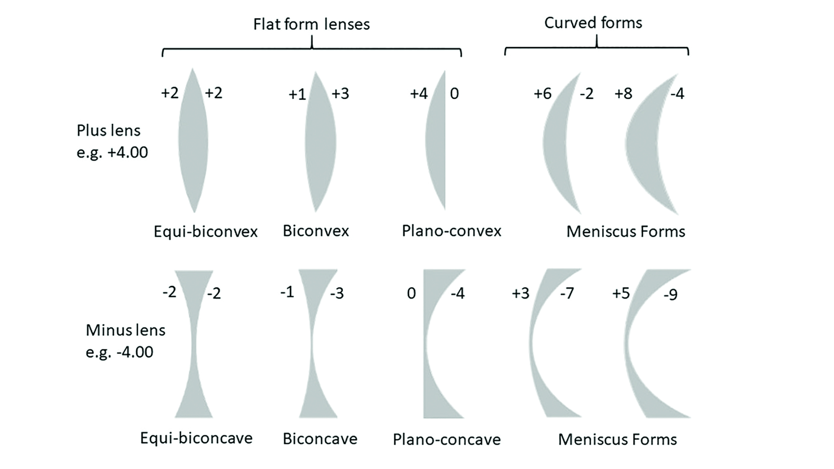 Figure 1: Nominal forms for lenses of +4.00DS and -4.00DS back vertex power
Aberrations
An aberration is any defect in an optical system such that the image produced is not a faithful reproduction of the object being viewed. In reality, almost all optical systems suffer from some form of aberration and lens designers trade off one aspect of image quality in order to gain another that they value more highly. For example, in a security camera a panoramic or fisheye lens has the advantage of an ultrawide field of view but at the expense of an image that is distorted around the edges.
Aberrations can be chromatic, where white light is dispersed into its constituent colours, or monochromatic, where the degradation of image quality occurs even with a single wavelength of light.
Chromatic aberration
Transverse chromatic aberration (TCA) is an issue for spectacle lens patients particularly in high prescriptions and large lens sizes. In multi-lens systems, such as telescopic low vision aids, TCA can be virtually eliminated by the use of achromatic doublets. These comprise of a positive lens and negative lens whose combined power totals that which is required, and are made of materials with differing Abbe values such that the dispersion caused by each lens is equal and opposite to the other such that they cancel each other out (and where F1/v1 = -F2/v2).
In spectacle lenses, as was covered in the previous article (see Optician 19.06.20), the only option is to use as high an Abbe value as possible if chromatic aberration is a problem.
Monochromatic Aberrations
The paraxial formulae, such as L + F = L’, used to calculate image formation by spherical refracting surfaces are only approximately correct. Gaussian paraxial theory assumes that for small angles (measured in radians) Sin A = A and the other terms can be ignored in the equation:
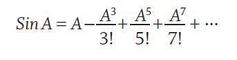
where, ! denotes a factorial, such that 5! = 5x4x3x2x1 = 120 and 7! = 5040 and so on.
With paraxial rays where A (in radians) is small or even 0, Sin A = A and so we can ignore the other parts of the expression. Here, any defect in the image produced is known as a first order aberration and refers simply to focusing error (for example as may be the case if the lens has the wrong power or is incorrectly positioned) or prismatic effect.
As the angle A between the incident ray and the optical axis increases the additional terms in the equation become increasingly significant. Because the 2nd term includes A3 (A cubed or A to the order of 3), it gives rise to so-called 3rd order aberrations. Terms involving A5 are called 5th order aberrations and so on.
The principle 3rd order monochromatic aberrations are known as Seidel aberrations after the German mathematician Ludwig von Seidel (1821-96).
The lack of 2nd or 4th order Seidel aberrations gives rise to confusion, especially as other systems developed since do include such terms. Most notable among these are the polynomial Zernike aberrations, which range from 1st to 10th order. These are of great importance in the development of aspheric lens surfaces and in the field of wavefront aberrometry, where they are used to measure the aberrations of the eye prior to customised laser refractive surgery or in the design of wavefront guided personalised aspheric lenses.
Experimental observation and trigonometric ray tracing through lenses using Snell’s Law (n sin i = n’ sin i’) enabled von Seidel to demonstrate that, as rays increasingly deviate from the paraxial, then the image is increasingly found to depart from the ideal.
There are five Seidel monochromatic aberrations:
- Spherical aberration
- Coma
- Distortion
- Curvature of field
- Oblique astigmatism
Spherical Aberration
Spherical aberration concerns paraxial rays (rays parallel to the optical axis) and causes rays that are refracted at the periphery of the lens to be focused closer to the lens because the prismatic effect exerted by the lens increases in proportion to the distance from the optical axis (figure 2). 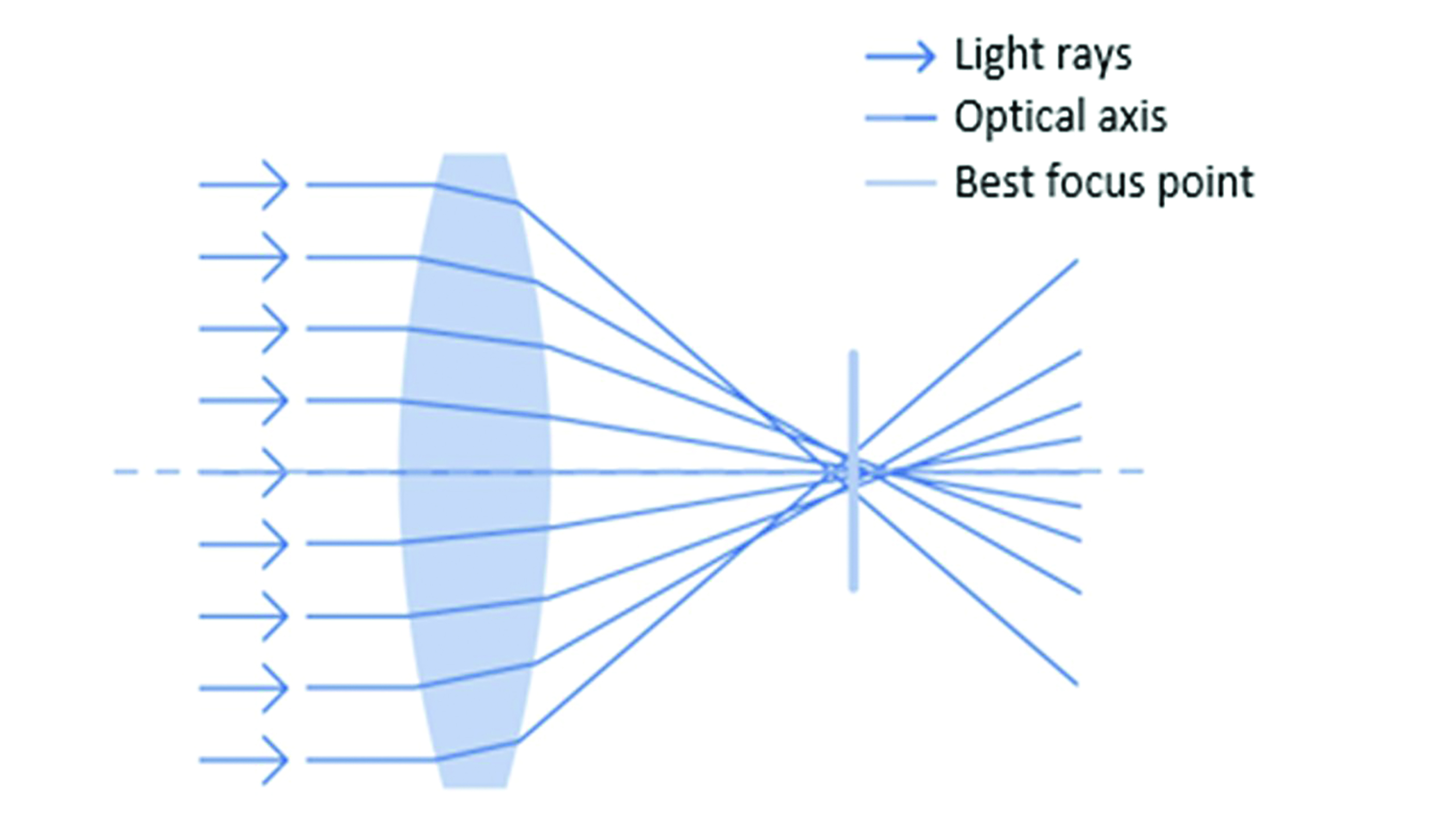 Figure 2: Spherical aberration
Coma
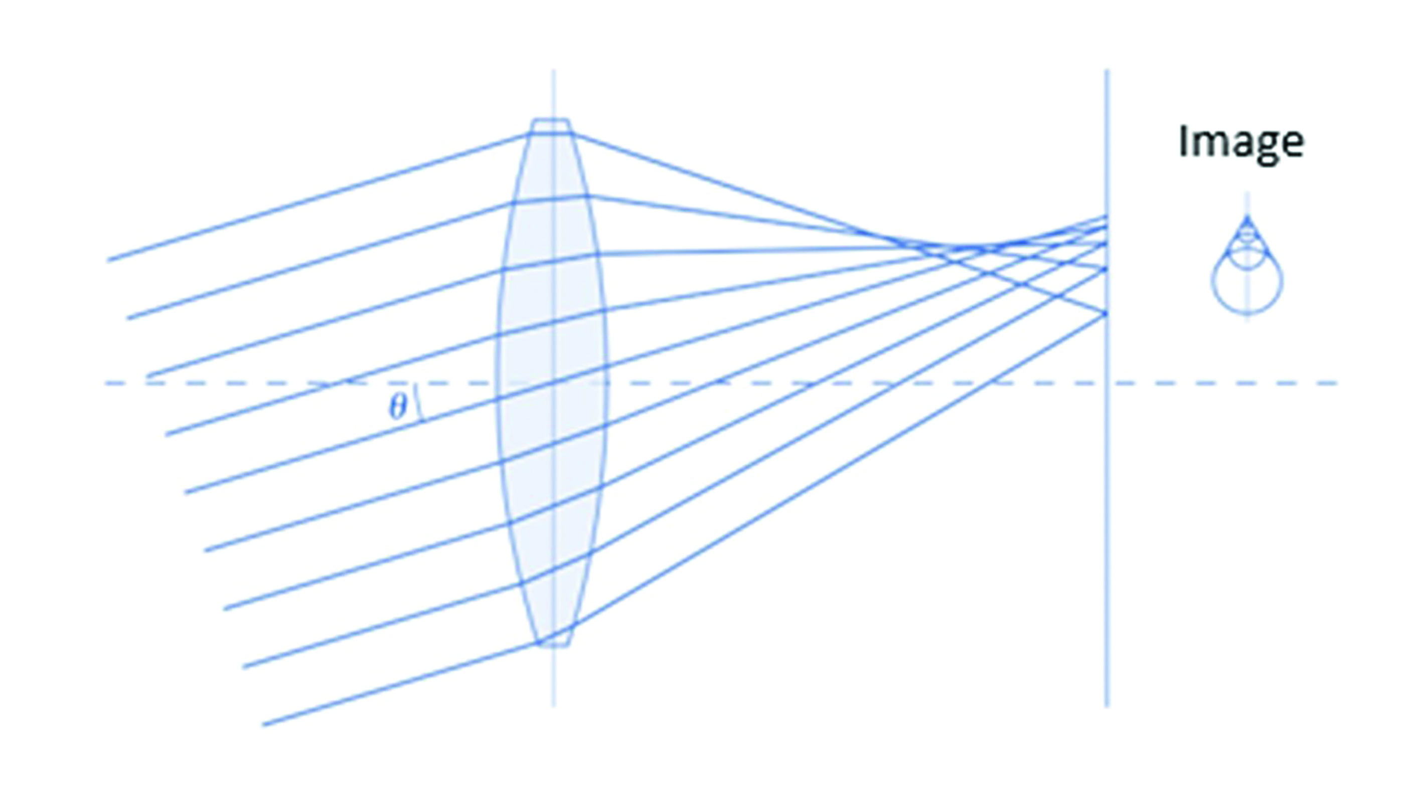
Coma can be considered as oblique spherical aberration (figure 3), and both are reduced significantly by the presence of a small aperture which increases depth of focus. Fortunately, under photopic (daylight) conditions, the eye’s pupil acts as an aperture stop to reduce any image degradation. However, patients may still suffer poor image quality when night driving, especially if their refraction is less than perfect, and both spherical and coma aberrations are thought to contribute to night myopia. Coma gains its name from the raindrop shaped image produced from a point object as it bears resemblance to a comet’s tail.
Distortion
Distortion is caused by peripheral areas of a lens causing greater magnification in plus powered lenses and minification in minus powered lenses. Positive lenses suffer from negative or pincushion distortion, whereas negative lenses suffer positive or barrel distortion (figure 4). Distortion is difficult to reduce with spherical surfaces and can only be corrected significantly with very steep lens forms. However, these are uneconomic and difficult to produce and often increase other aberrations to the detriment of final image quality.
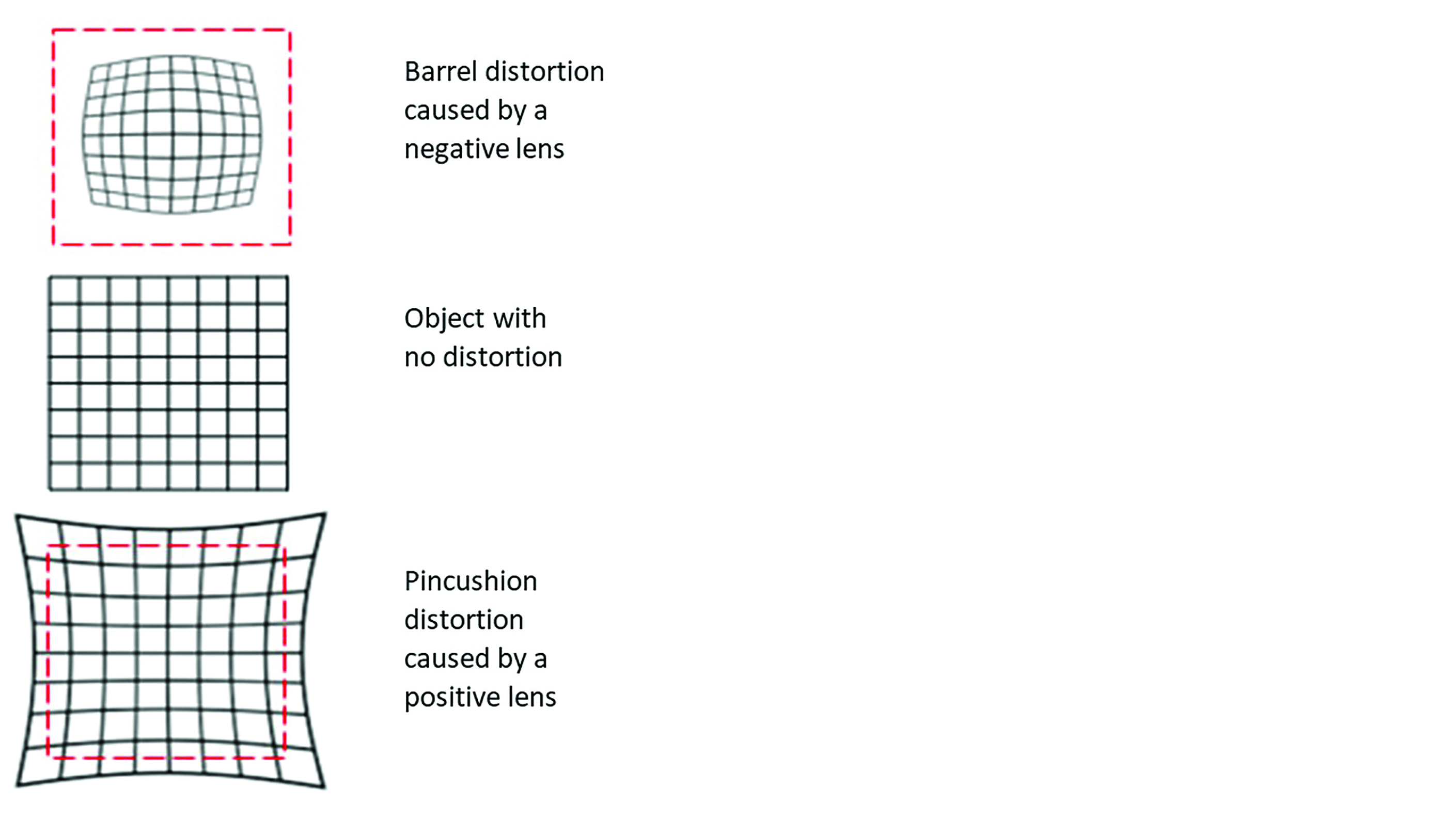 Figure 4: Distortion
Curvature of field (power error)
Curvature of field relates to the fact that with spectacle lenses incorporating spherical surfaces it is not possible to produce a perfect lens. And even when the major causes of poor image quality have been completely eliminated, it is not possible to produce a clear image on the far point sphere for all off-axis visual points. The so-called Petzval surface marks the position of the image points from all equidistant off-axis object positions. The difference between the far point sphere and the Petzval surface is known as image difference or image shell error and the aberration is known as curvature of field or power error (figure 5).
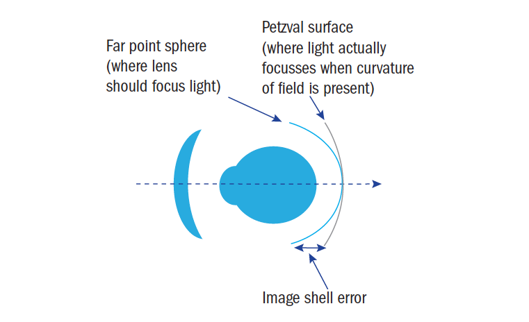 Figure 5: Curvature of field
In practice, if a plus lens is designed such that the Petzval surface is posterior to the far point sphere (or anterior in myopes) then for peripheral directions of gaze the patient can accommodate to place the image on the far point sphere and gain clear peripheral vision. For this reason, power error (curvature of field) is considered less of a problem than oblique astigmatic error.
Oblique astigmatism
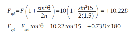
When a pencil of light strikes a spherical surface obliquely, it will have a different angle of incidence in the vertical meridian compared to the horizontal. Consider a +10.00DS trial lens, n=1.5, placed before the eye such that it is not tilted in any way, and the optical axis aligns with the visual axis when the eye is in the primary position (figure 6a). Incident light will strike the lens normally at the optical centre and the angle of incidence in both vertical and horizontal meridians would measure 0°. If the lens now has 15° of pantoscopic tilt applied (figure 6b) then the horizontal angle of incidence would still be 0°, but in the vertical meridian, θ = 15°.
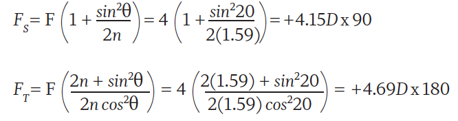
Applying face-form angle has a similar, though orthogonal, effect and can be calculated in the same way. Alternatively, the crossed cylinders may be calculated in the sagittal plane and tangential plane (which contains the optical axis) respectively. Let us consider a wraparound sunglass, power +4.00DS R&L where the face-form angle θ (figure 7) is 20° right and left, and n = 1.59.
In order to minimise the effects of oblique astigmatism in a given lens, the centre of rotation condition must be observed. At the point where the visual axis intersects the optical centre (back vertex) of the lens, it must coincide with the optical axis. 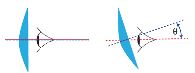
Figure 6a: Alignment of optical and visual axes Figure 6b: Pantoscopic angle of 15°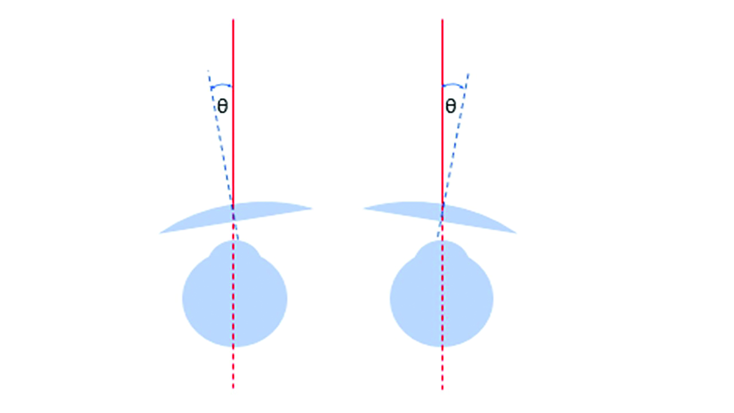
Figure 7: Face-form angle
The ideal face-form angle is therefore zero. However, in terms of pantoscopic tilt, in order to avoid the patient looking beneath the lower rim or the lenses rubbing on the eye lashes, a tilt of around 10˚ is typical. The pantoscopic angle should be measured along with heights to pupil centre and the optical centres positioned 1mm downwards for every 2˚ of tilt.
Having satisfied the centre of rotation condition to optimise lens performance, most lens forms still suffer from some degree of oblique astigmatism when the eye views an object away from the optical axis (figure 8). 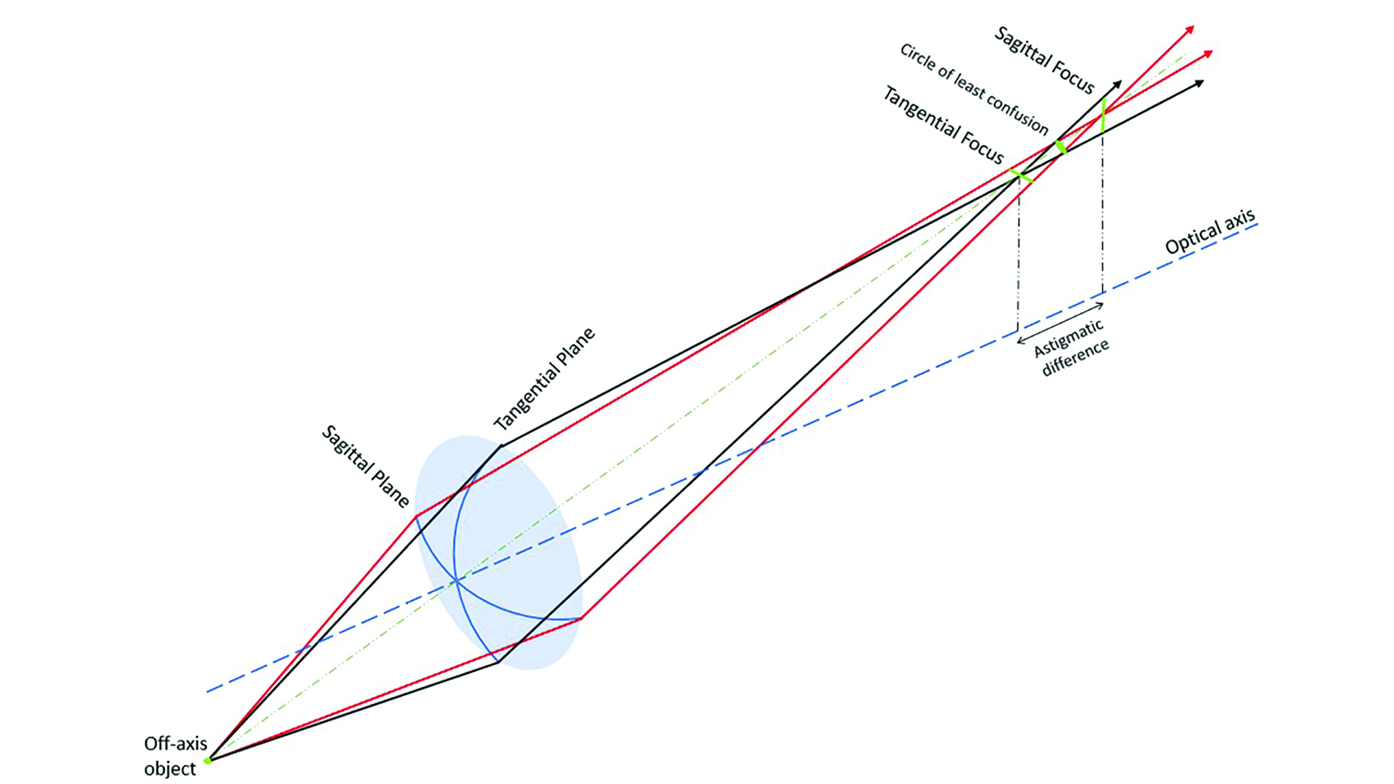
Figure 8: An astigmatic pencil formed by a spherical lens due to the oblique position of the object
How the patient will perceive the oblique astigmatism will depend upon the position of the tangential and sagittal line foci (and associated circle of least confusion) relative to the far point. For a series of point objects equidistant from the lens (with the same z coordinates, as in figure 9) and describing a circle centred upon the optical axis, the tangential and sagittal line foci will describe separate image shells, the so-called ‘teacup and saucer’. The closer the objects to the optical axis, the less the separation between tangential and sagittal image and the lower the amount of oblique astigmatism present.
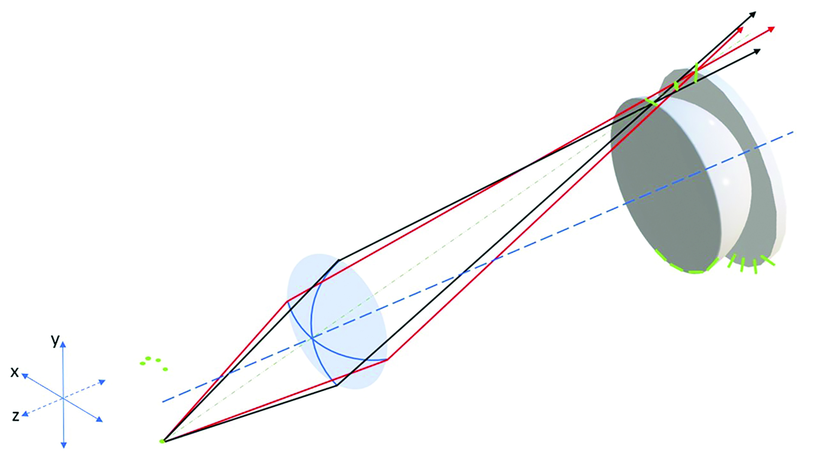
Figure 9: The ‘teacup and saucer’ that represent the tangential and sagittal image shells respectively
Lens designers can select base curves to completely eliminate oblique astigmatism such that oblique rays are focused to a point (figure 10). However, it is not possible to remove both oblique astigmatism completely and place the image on the far point sphere so with so-called point focal lenses, some curvature of field (power error) remains.
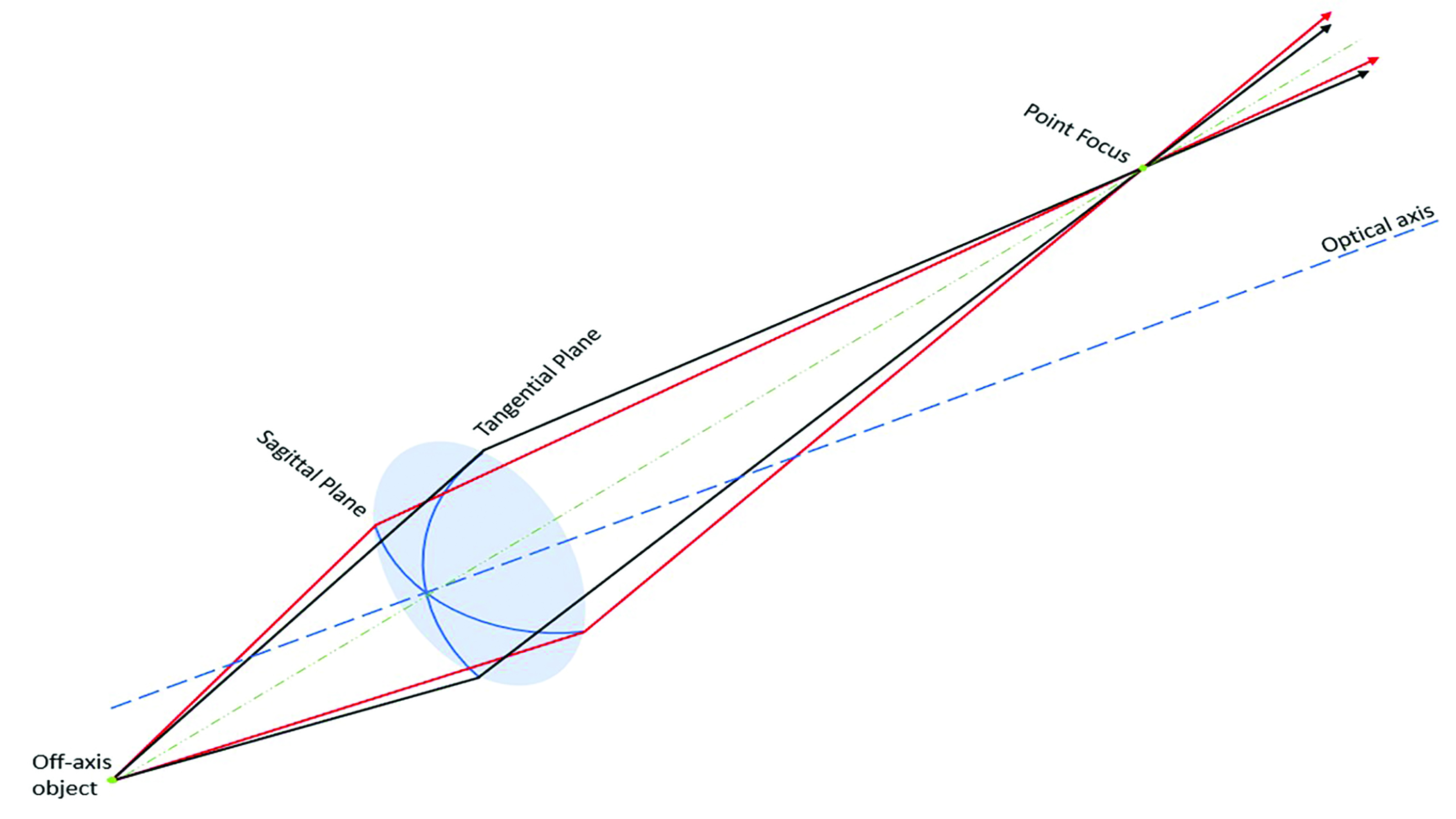 Figure 10: A lens that is free from oblique astigmatism
Field diagrams
Comparison of the imaging properties of lenses is best conducted via field diagrams which plot the direction of gaze (ocular rotation) against the focal power, both tangential and sagittal. Figure 11 shows the field diagram for a +4.00DS lens made in plano-convex form. It can be seen that at 30˚ eccentricity the sagittal power is around +4.25D and the tangential power +5.25D. In other words, during oblique gaze, the patient is experiencing +4.25/+1.00x180 when they have been prescribed +4.00DS. The field diagrams presented here have been redrawn from data from a variety of sources – readers may be more accustomed to a vertical format.  Figure 11: A field diagram plotting the ocular rotation (direction of gaze) against the tangential and sagittal power of a +4.00DS plano-convex lens
A Cautionary Note
It is worth bearing in mind that trial lenses are usually of flat form and that all flat form lenses suffer significant oblique astigmatism. It is therefore vital that the prescriber ensures that the trial frame is centred precisely, with each trial lens’s optical centre exactly coincident with the visual axis (pupil centre) and with a pantoscopic tilt of 0˚ if error in the measurement of refractive error is to be avoided.
Best Form Lenses
A best form lens is one that seeks to reduce or eliminate certain stated aberrations to provide the patient with the best vision possible. Students should note that best form is about image forming properties and not about a lens being thinner, flatter or lighter. The standard ‘good, better, best’ patter used in practice when dispensing is not what ‘best form’ refers to. It concerns vision, not cosmetic benefits, and is frequently described incorrectly.
Through experimentation and accurate ray tracing, it was discovered that making lenses in different forms would reduce or eliminate the key aberrations curvature of field and oblique astigmatism. Since both aberrations cannot be simultaneously eliminated, best form lenses seek to optimise one at the expense of the other. An early best form lens, satisfying the condition for best compromise with a single lens blank from which all lenses would be surfaced, was the periscopic form where plus lenses were made with a -1.25DS back surface and minus lenses a +1.25DS front surface.
Tscherning’s ellipses
Much of the work on best form lenses was published by Dr Marcus Tscherning in 1904, working theoretically using seven-digit log tables to plot the rays through lenses across the prescription range in order to eliminate oblique astigmatism. Others then graphed the results of his work to produce Tscherning’s ellipses (figure 12), plotting front surface power F1 against back vertex power Fv’ although different authors often plot back surface power instead because modern lenses usually have their base curve on the back surface. 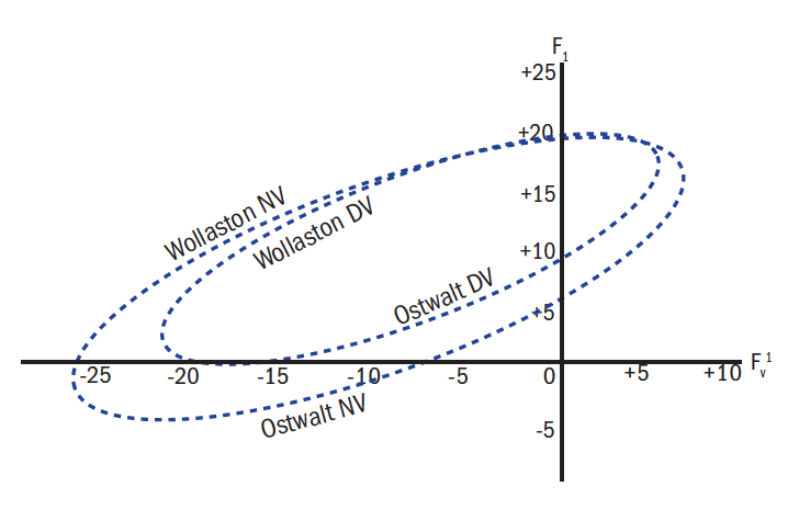 Figure 12: Tscherning’s ellipses
It is important to note that there is a different ellipse for every material (refractive index), every working distance and also every centre of rotation distance (CRD). However, ellipses are generally published for distance vision and a near working distance of a third of a metre and assume a CRD of 27mm. For any given back vertex power that lies within the extremes of the ellipse, there are two possible forms; a steeper Wollaston form and a shallower Ostwalt form. Although the Wollaston form has the advantage that, over much of the range of common prescriptions, the distance and near forms are the same and that it also suffers less distortion than the Ostwalt form, it has never been adopted commercially as the lenses are very thick and bulbous, have a large ‘plate’ thickness and can necessarily only be produced in small diameters.
Figure 12 shows an approximate ellipse for a standard glass material. It can be seen that for a back vertex power of -5.00DS there are two distance forms; the flatter Ostwalt form requires a front surface power of +5.00D and the steeper Wollaston form requires F1 = +17.50D.
Note that best form is only available across the power range from approximately -27.00D to +7.00D in this index. The range can be extended in the negative direction by increasing the refractive index with best form available in powers beyond -40.00 in 1.8 glass materials. Unfortunately for moderately high positive powers, best form lenses cannot be designed using spherical curves.
Different ellipses can also be plotted depending on the lens design parameters and which best form design philosophy is being employed, there being three major types, as follows:
Point focal lenses
Point focal lenses are the most curved of the best form designs and are designed to eliminate oblique astigmatism completely. As shown in figure 13, the sagittal and tangential image shells are coincident and oblique power is consistent with that prescribed up to around 10˚ ocular rotation. At 40˚, the lens is underpowered by 0.40D. This will not be a problem if the patient has sufficient accommodation to overcome this comfortably.
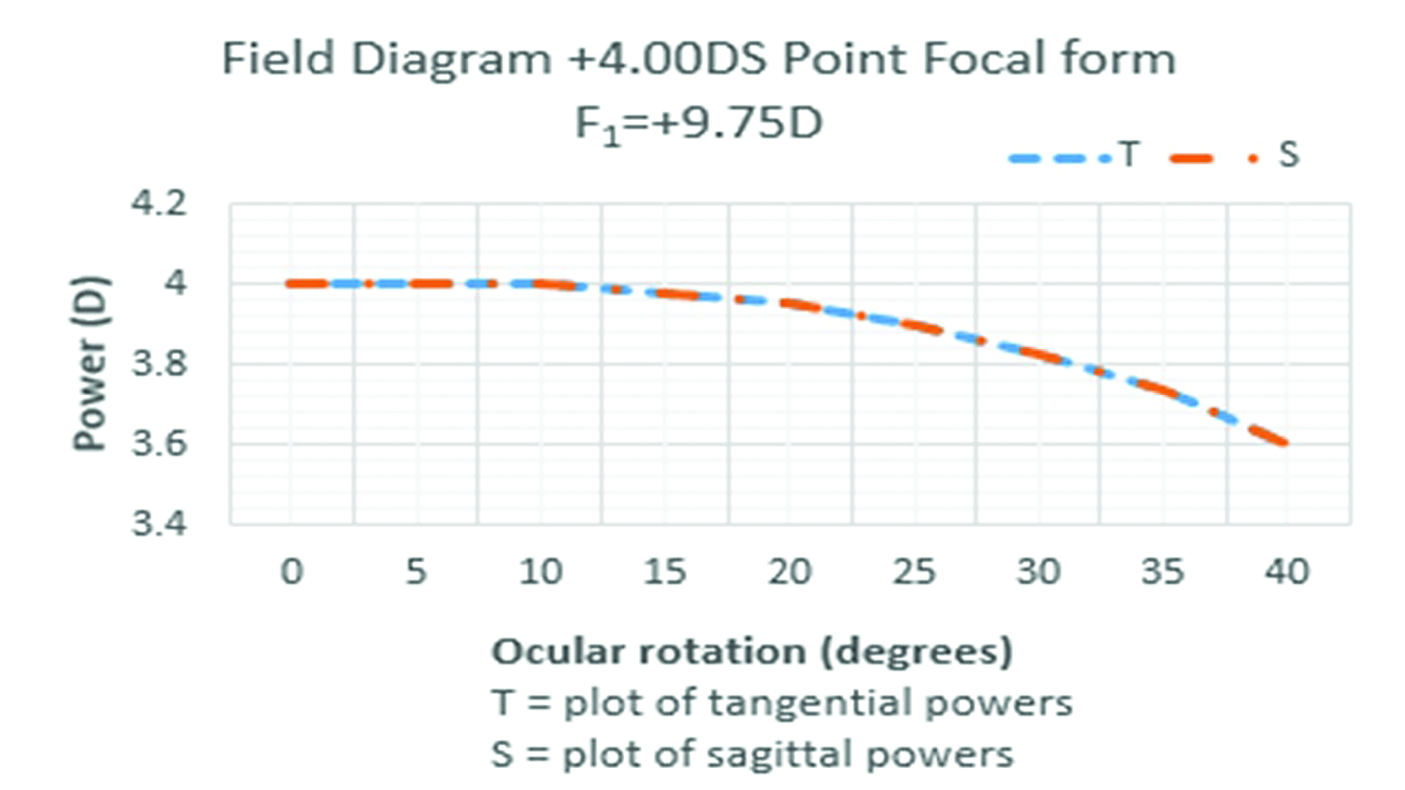 Figure 13: Field diagram for a +4.00DS point focal form lens
Percival form lenses
The flattest of the standard best form designs is the Percival form which seeks to place the circle of least confusion on the far point sphere such that the tangential and sagittal image shells are equidistant in front of and behind the far point sphere respectively. The mean oblique error is zero so that the mean oblique power experienced is as prescribed in all directions of gaze without any need to accommodate. At 30˚ eccentricity, the unwanted astigmatism is about equivalent, on our +4.00 lens, to having an unwanted paraxial cylinder of 0.25DC (figure 14).
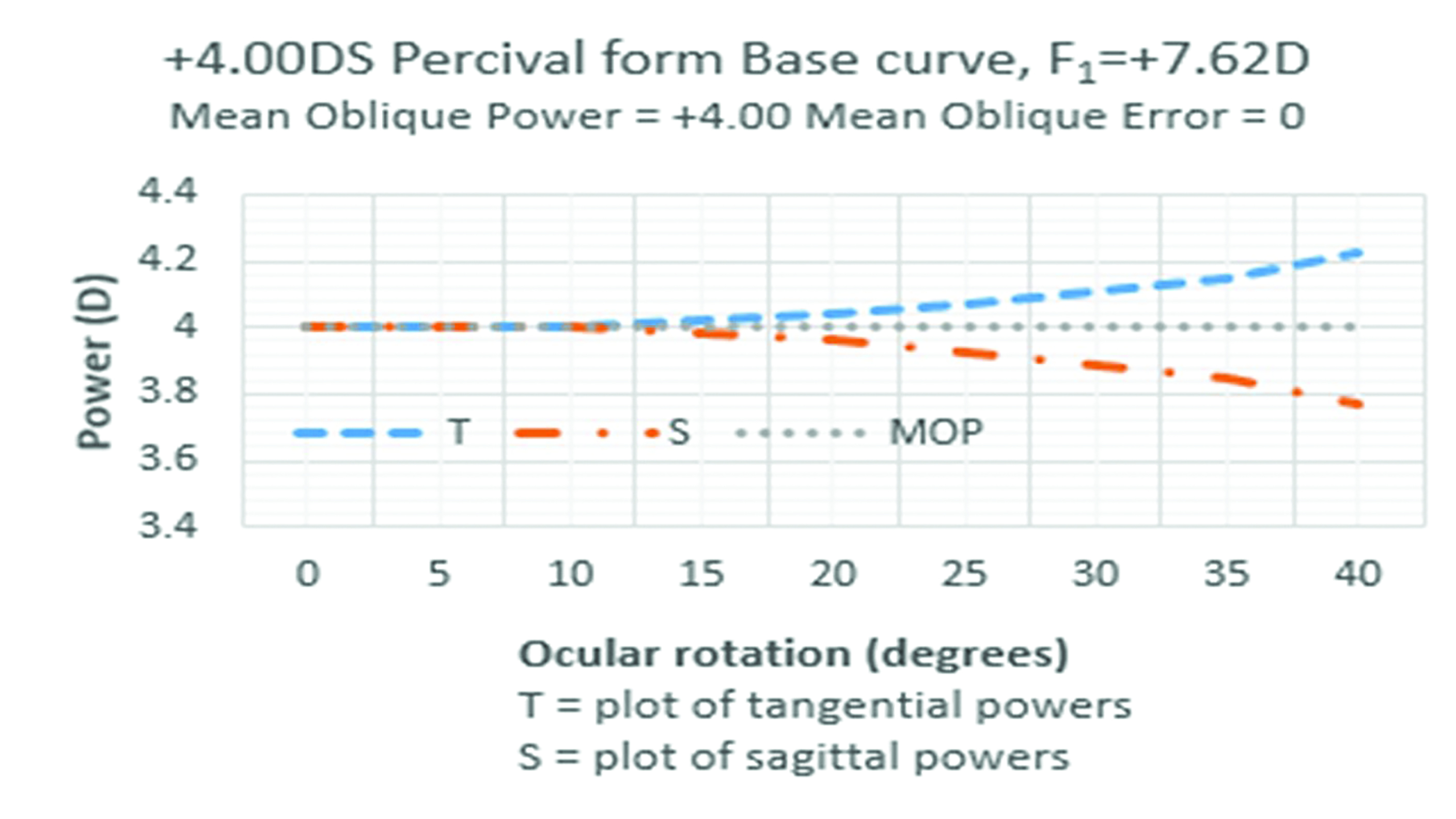 Figure 14: +4.00DS Percival form lens
Minimum tangential error
The third type of best form lens is the form stock lenses most closely approximate to in practice, is the minimum tangential error (MTE or Min T Error) design which lies between the point focal and Percival forms in terms of its curvature. As can be seen from figure 15, the tangential image shell fits exactly to the prescribed power and the only aberration is in the sagittal plane. Relating this to figure 9, this means that when viewing a large object like a cartwheel, the rim of the wheel would be clear and the radial objects (the spokes) would be slightly blurred when viewed obliquely. The patient could accommodate in this example to place the circle of least confusion on the retina when viewing oblique objects, but at 40˚ the 0.25DC residual astigmatism is very well tolerated.
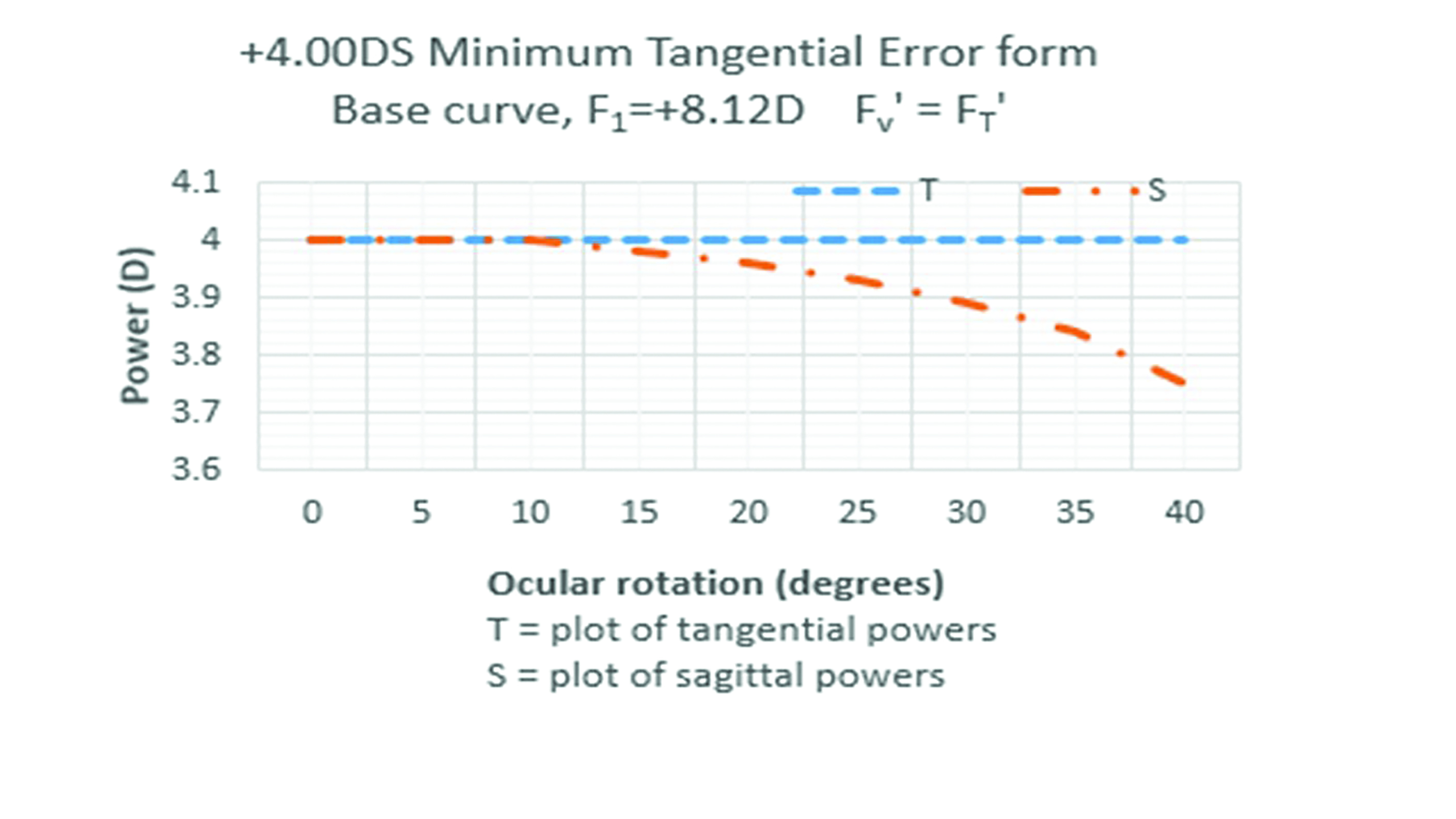 Figure 15: +4.00DS minimum tangential error form lens
The MTE lens is the appropriate choice as the standard lens form because it is the best compromise on a number of fronts. At non-standard centre of rotation distances, it will act either as a point focal lens (if fitted further away) or a Percival form if fitted closer. It is less bulbous and therefore available to wider diameters than point focal forms and is better cosmetically.
Compromises
The optimum performance of best form lenses requires the exact base curve to be selected for each power of lens and for this to be matched exactly to the eye’s centre of rotation distance which is almost always unknown and based on averages. Clearly toric lenses will only be ‘best form’ in one meridian or a compromise must be selected. Additionally, there is the issue of semi-finished lenses only being available in limited base curves, typically set at approximately 2.00D intervals. As patients’ prescriptions change such that they cross a boundary between base curves, they may well notice this change and not tolerate it. The base curve of the old lens can be determined using the lens measure and, if different a lens ordered to match. Some manufacturers change base curves at more frequent intervals to overcome this departure from the best optical form. An alternative is to use an aspheric lens, where base curves are changed much more frequently. Aspheric lenses along with lenticulars will be the subject of the next article.
Conclusion
Single vision lens technology has advanced considerably in recent decades. The change from the exclusive use of mineral (glass) lenses to organic (plastic) lenses is now almost complete. In terms of lens designs however, despite technology advancing at a rapid pace in the past 20 years, the majority of single vision lenses dispensed in the UK are to designs first introduced over a century ago. This is at least in part because mathematically-derived best form lenses offer tried and tested solutions to visual problems for minus and low to moderate plus prescriptions.
Nevertheless, the hard work of lens designers to eliminate problematic aberrations is, to a certain extent, undone by careless refraction and poor quality dispensing; in particular the failure to take into account properly the centre of rotation condition during refraction, frame fitting or when taking measurements.
In a previous life, the author worked as a management consultant to the optical industry and was involved with several companies, helping them improve dispensing standards. One customer satisfaction survey of patients revealed that over 30% of them ‘lacked confidence’ in their spectacles. Another group of practices had a ‘returns rate’ of over 12%. That meant that one in eight pairs of spectacles dispensed were returned and had to be either remade or refunded. This does not include the larger group of patients whose visual problems were solved by understanding how frame adjustments can make a very considerable difference to the optical performance of a lens.
Another reason perhaps that our industry sticks with century-old technology is that best form lenses are very forgiving of error. Modern aspheric and atoric lenses (the subject of the next article) are much less likely to be tolerated by the patient if any measurements are incorrect or the centre of rotation condition is not adhered to. Our standard minimum tangential error lenses on the other hand, if not fitted correctly, may act as a Percival or point focal lens instead. Nevertheless, the evidence suggests we could do more to help patients achieve the best visual acuity possible in all directions of gaze and, just as we do with progressive power lenses, we should do with single vision lenses and bring ourselves and our patients up to date.
Peter Black MBA FBDO FEAOO is senior lecturer in ophthalmic dispensing at the University of Central Lancashire, Preston, and is a practical examiner, practice assessor, exam script marker, and past president of the Association of British Dispensing Opticians.
Tina Arbon Black BSc (Hons) FBDO CL is director of accredited CET provider Orbita Black Limited, an ABDO practical examiner, practice assessor and exam script marker, and a distance learning tutor for ABDO College.
Further Reading
The following texts have been used in the compilation of this
article:
- Millodot, Michel. Dictionary of Optometry and Vision Science. 8th. s.l. : Elsevier, 2018.
- Schwartz, Steven H. Geometrical and Visual Optics. A clinical introduction. 3rd. New York : McGraw Hill Education, 2019.
- Jalie, M. The Principles of Ophthalmic Lenses. 5th. London : Association of British Dispensing Opticians, 2016. ISBN 978-0-900099-02-1.
- Falk, David S, Brill, Dieter and Stork, David. Seeing the light. Optics in nature, photgraphy, color, vision and holography. 2nd. Vermont : Echo Point Books and Media LLC, 2020. ISBN 978-1-63561-923-2.
- Pedrotti, Frank L, Pedrotti, Leno M and Pedrotti, Leno S. Introduction to Optics. Cambridge : Cambridge University Press, 2018. ISBN 978-1-10842826-2.
- Jalie, Mo. Ophthalmic Lenses and Dispensing. 2nd. London : Butterworth-Heinemann, 1999. ISBN 0 7506 5526 7.
- Hecht, Eugene. Optics Global Edition. 5th. Harlow, Essex : Pearson Education, 2017. ISBN 978-1-292-09693-3.
- Born, Max and Wolf, Emil. Principles of Optics 60th Anniversary Edition. Cambridge : Cambridge University Press, 2019. ISBN 978-1-108-47743-7.
- Alonso, Jose, Gomez-Pedrero, Jose A and Quiroga, Juan A. Modern Ophthalmic Optics. Cambridge : Cambridge University Press, 2019. ISBN 978-1-107-11074-8.
- Sasian, Jose. Introduction to Lens Design. Cambridge : Cambridge University Press, 2019. ISBN 978-1-108-49432-8.
- Yacoubian, Araz. Optics Essentials. An interdisciplinary guide. Boca Raton, Florida : Taylor & Francis, 2019. ISBN 978-0-367-37791-5.
- Fowler, Colin and Latham Petre, Keziah. Spectacle Lenses: Theory and Practice. Oxford : Butterworth Heinemann, 2001. ISBN 978-0-7506-2370-5.
- Brooks, Clifford W and Borish, Irvin M. System for Ophthalmic Dispensing. St Louis, Missouri : Butterworth Heinemann Elsevier, 2007. ISBN 978-0-7506-7480-5.