Download
1 / 112
2.51k likes | 6.05k Views
Unit –II: Impulse Water Turbines. Introduction to Hydro power plant classification of hydraulic turbines construction principle of working velocity diagrams and analysis design aspects performance parameters performance characteristics specific speed selection of turbines

E N D
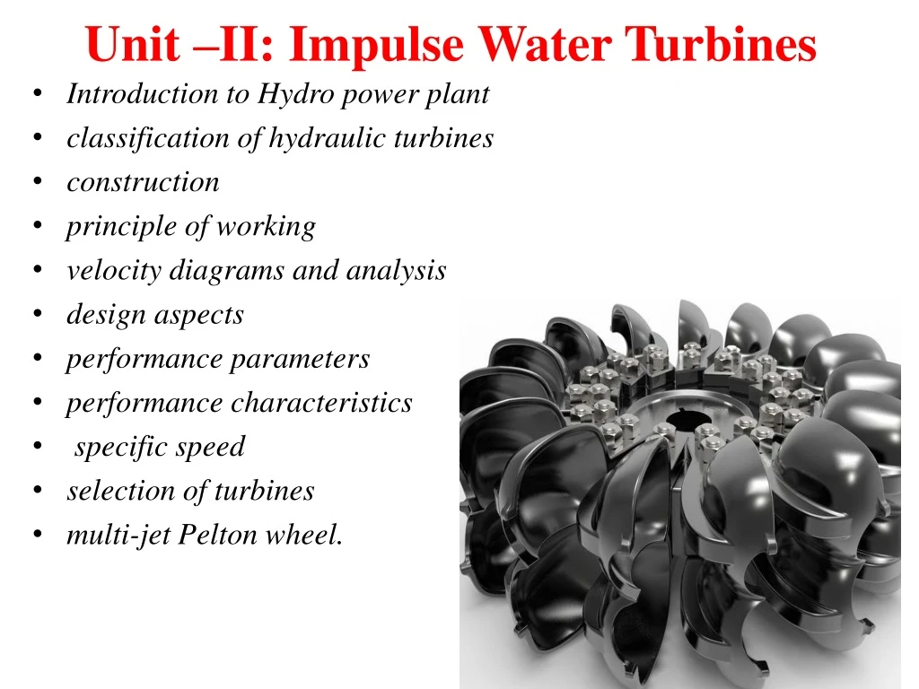
Unit –II: Impulse Water Turbines • Introduction to Hydro power plant • classification of hydraulic turbines • construction • principle of working • velocity diagrams and analysis • design aspects • performance parameters • performance characteristics • specific speed • selection of turbines • multi-jet Pelton wheel.
Early Hydraulic Turbines • Hydraulic Turbines (water wheels) have been in use for centuries. • Hydraulic Turbines convert the potential energy of water into work. • Basic Turbines are either Reaction or Impulse. • First developed in the mid 1800’s. • Power outputs range up to 1,000 Mw. • Included are Tidal and Wind Turbines. Undershot Style Overshot Style
Introduction • The device which converts hydraulic energy into mechanical energy or vice versa is known as Hydraulic Machines. • The hydraulic machines which convert hydraulic energy in to mechanical energy is called as turbine • A water turbine is a rotary machine that converts kinetic and potential energy of water into mechanical work. • Water turbines are mostly found in dams to generate electric power from water kinetic energy. • Water turbines take energy from moving water. Flowing water is directed on to the blades of a turbine runner, creating a force on the blades. Since the runner is spinning, the force acts through a distance to produce work. In this way, energy is transferred from the water flow to the turbine.
Turbine TURBINES:- Turbines are defined as hydraulic machine which converts hydraulic energy into mechanical energy. Turbine is a device that extracts energy from a fluid (converts the energy held by the fluid to mechanical energy) PRINCIPLE:- This mechanical energy is used in running an electric generator which is directly coupled to the shaft of turbine Thus mechanical energy is converted into electrical energy.
DEFINATION OF TURBINES:- IMPULSE TURBINE:- If at inlet of turbine, the energy available only kinectic energy, the turbine is known as impulse turbine. Ex. Pelton Wheel Turbine REACTION TURBINE:- If at inlet of turbine, the water possesses kinetic energy, the turbine iss known as reaction turbine. Ex. Francis Turbine, Kaplan Turbine RADIAL FLOW TURBINNE:- If the water flow in radial direction through runner, the turbine is called radial flow turbine.
INWARD RADIAL FLOW TURBINE:- If the water flows from outward to inward radial flow turbine. OUTWARD RADIAL FLOW TURBINE:- If the water flows from inward to outward radial flow turbine. AXIAL FLOW TURBINE:- If the water flow through the runner along the direction parallel to the axis of rotation of the runner, the turbine is called axial flow turbine. MIXED FLOW TURBINE:- If the water flows the runner in the radial direction but leaves in the direction parallel to the axis of rotation of the runner, the turbine is called mixed floe turbine. TANGENTIAL FLOW TURBINE:- If the water flows along the tangent of runner, the turbine is known as tangential flow turbine .
Power from water • In both types of turbines the fluid passes through a runner having blades. The momentum of the fluid in the tangential direction is changed and so a tangential force on the runner is produced. The important feature of the impulse machine is that there is no change in static pressure, across the runner, while for the reaction turbine there are considerable changes in pressure energy.
Power from water Applying the first law of thermodynamics (principle of energy conservation) to a “control volume”. Assuming a steady flow operation of the turbine per unit of mass (j/kg). loss Where ws is the work performed by the fluid on the turbine. Actual work (wa) is the total useful specific energy supply by the liquid. The total dynamic head of the turbine is described as: The hydraulic power (Ph) is the useful power supplied by the liquid to the turbine.
H Power from water If a mass M of water falls through a distance H, its loss of potential energy is MgH As it falls, the water could be made to do work, and in theory this work would also equal MgH In a hydro power plant, the water flows continuously, and the rate of doing work is is the mass flow rate
Generator Turbine Hydro-electric power plant Water collects in the upper reservoir, flows through the turbine and is then discharged at low level. The rate of power production is ideally, and in practice, where ηis the efficiency of the process. In a real system, energy will be dissipated as heat in the generator, the turbine and in the connecting pipelines
Hg = Gross Head hf = Head Loss due to Friction = Where V = Velocity of Flow in Penstock L = Length of Penstock D = Dia. of Penstock H = Net Head = Hg- hf
Layout of a Hydroelectric Power Plant Dam Tail Race Penstock Buckets Nozzle Tail Race Jet of water
Parts Of A Hydroelectric Plant • Dam. Raises the water level of the river to create falling water. Also controls the flow of water. The reservoir that is formed is, in effect, stored energy. This is also known as head race level • Penstock. Pipes of large diameter called Penstocks which carry water under pressure from storage reservoir to the turbines . These pipes are usually made of steel or reinforced concrete. • Turbine. The force of falling water pushing against the turbine's blades causes the turbine to spin. The turbine converts the kinetic energy of falling water into mechanical energy. • Generator. Connected to the turbine by shafts and possibly gears so when the turbine spins it causes the generator to spin also. Converts the mechanical energy from the turbine into electric energy. Generators in hydropower plants work just like the generators in other types of power plants. • Transmission lines. Conduct electricity from the hydropower plant to homes and business • Tailracewhich is a channel carrying water away from the turbine after the water has worked on the turbines . The water surface in the tailrace is also referred to as tailrace . • .
Basic Elements in Hydro Electric Power Plant 1.Reservoir : Reservoir is used to Store Large amount water. 2.Dam : It is Structure of considerable height built across the reservoir. It develops a reservoir to store water & Built Head for power generation. 3. Trash Rack : It is provided for preventing entry of debris like dust, dirt etc. from the dam. Because it may damage to turbine blades & Chock the flow. 4.Gate : It is provided to control the flow of water from the reservoir to the turbine. 5.Penstock : A Pipe which carries water from reservoir to turbine house is called penstock. It is a large of 1 m to 2 m in diameter made up of concrete to withstand high pressure. 6.Turbine : Turbine is used to convert Kinetic Energy to Mechanical Energy.
Head of Turbine Gross Head ( Hg ) It is the difference between head race level and tail race level when no water is flowing. It is also known as total head of the turbine Effective Head or Net Head (H) Net head or effective head is the actual head available at the inlet of the turbine. When water is flowing from head race to the turbine, a loss of head due to friction between water and penstock occurs. Though there are other losses also such as loss due to bend, pipe fittings, loss at entrance of the penstock, etc. These all having small magnitude as compared to head loss due to friction. Euler's Head: It is defined as energy transfer per unit weight H = Hg- hf Where , H = Net head Hg = Gross head hf= Head Loss due to Friction= Where F= cofficient of friction of penstock V = Velocity of Flow in Penstock L = Length of Penstock D = Dia. of Penstock g = acceleration due to gravity
Efficiency of Turbine Hydraulic Efficiency It is the ratio of the power developed by the runner of a turbine to the powersupplied by the water at the inlet of a turbine. Since the power supplied is hydraulic, and the probable loss is between the striking jet and vane it is rightly called hydraulic efficiency. Mechanical Efficiency The power delivered by water to the runner of a turbine is transmitted to the shaftof the turbine. It is the ratio of the power available at the shaft of the turbine to the power developed by the runner of a turbine. This depends on the slips and other mechanical problems that will create a loss of energy i.e. friction.
Overall Efficiency It is the ratio of the power available at the shaft to the power supplied by the water at the inlet of a turbine. Volumetric Efficiency The volume of the water striking the runner of a turbine is slightly less than the volume of the water supplied to the turbine. Some of the volume of the water is discharged to the tail race without striking the runner of the turbine. Thus the ratio of the volume of the water actually striking the runner to the volume of water supplied to the turbine is defined as volumetric efficiency.
Different Efficiencies Mechanical Efficiency 2. Volumetric Efficiency Some quantity of water always misses the bucket and directly passes to the tail race without doing any useful work, hence volumetric efficiency is always less than 100% (97% to 99 %)
3.Overall Efficiency From all efficiencies we have
Losses of Hydraulic Turbines • Various types of losses that occur in a power plant are given below: (a) Head loss in the penstock: This is the friction loss in the pipe of a penstock. (b) Head loss in the nozzle: In case of impulse turbines, there is head loss due to nozzle friction. (c) Hydraulic losses: In case of impulse turbines, these losses occur due to blade friction, eddy formation and kinetic energy of the leaving water. In a reaction turbine, apart from above losses, losses due to friction in the draft tube and disc friction also occur. (d) Leakage losses: In case of impulse turbines, whole of the water may not be striking the buckets and therefore some of the water power may go waste. In a reaction turbine, some of the water may be passing through the clearance between the casing and the runner without striking the blades and thus not doing any work. These losses are called leakage losses. (e) Mechanical losses: The power produced by the runner is not available as useful work of the shaft because some power may be lost in bearing friction as mechanical losses. f) Generator losses: Due to generator loss, power produced by the generator is still lesser than the power obtained at the shaft output.
Classification of Hydraulic Turbines • According to the type of energy at inlet or the action of the water on the blade • Impulse turbine • In an Impulse turbine, all the available energy of the water is converted into kinetic energy or velocity head by passing it through a convergent nozzle provided at the end of penstock. • So at the inlet of the turbine, only kinetic energy is available. • Here the pressure of water flowing over the turbine blades remains constant. (i.e. atmospheric pressure) • Examples: Pelton wheel, Turgo-impulse turbine, Girard turbine, Banki turbine, Jonval. • Reaction turbine • In a reaction turbine, at the entrance to the runner, only a part of the available energy of water is converted into kinetic energy and a substantial part remains in the form of pressure energy. • So at the inlet of the turbine, water possesses kinetic energy as well as pressure energy. • As the water flows through the turbine blades, the change from pressure energy to kinetic energy takes place gradually. • For this gradual change of pressure, the runner must be completely enclosed in an air-tight casing and the passage should be full of water. • The difference of pressure between the inlet and outlet of the runner is called reaction pressure, and hence these turbines are known as reaction turbine. • Examples: Francis turbine, Kaplan turbine, Propeller turbine, Thomson turbine,
According to the direction of flow through runner Tangential flow turbine In tangential flow, the water strikes the runner in the direction of tangent to the path of rotation of runner. OR The water strikes the vane/bucket along the tangent of the runner. Example: Pelton wheel Radial flow turbine In radial flow, water flows through the turbine along the direction normal to the axis of rotation (i.e. radial direction). A radial flow turbine is further classified as inward or outward flow depending upon whether the flow is inward from the periphery to the center or outward from center to periphery. Example: Old Francis turbine Axial flow turbine In an axial flow, water flows along the direction parallel to the axis of rotation of the runner. Here water flows parallel to the turbine shaft. Examples: Kaplan turbine, Propeller turbine Mixed flow turbine In mixed flow, water enters the runner in the radial direction and leaves in the direction parallel to the axis of rotation (i.e. axial direction). Example: Modern Francis turbine.
According to the head at the inlet of the turbine High head turbine High head turbines which operates under high head (above 250m) and requires relatively less quantity of water. Example: Pelton wheel turbine Medium head turbine Medium head turbines which operate under medium head (60m to 250m) and require medium flow rate. Example: Modern Francis turbine Low head turbine Low head turbines which operate under head up to 30m and require very large quantity of water. Example: Kaplan and Propeller turbine According to specifice speed Low specific speed turbine For Pelton wheel turbine with single jet, For Pelton wheel turbine with double jet, Medium specific speed turbine For Francis turbine, High specific speed turbine Kaplan and other Propeller turbine,
Types of turbines Turbines can be classified on the basis of: • Head and quantity of water available • Hydraulic action of water • Direction of flow of water in the runner • Specific speed of turbines • Disposition of the shaft of the runner
Classification of turbines • Based on head and quantity of water According to head and quantity of water available, the turbines can be classified into a) High head turbines b) Medium head turbines c) Low head turbines a) High head turbines High head turbines are the turbines which work under heads more than 250m. The quantity of water needed in case of high head turbines is usually small. The Pelton turbines are the usual choice for high heads. b) Medium head turbines The turbines that work under a head of 45m to 250m are called medium head turbines. It requires medium flow of water. Francis turbines are used for medium heads. c) Low head turbines Turbines which work under a head of less than 45m are called low head turbines. Owing to low head, large quantity of water is required. Kaplan turbines are used for low heads.
Classification of turbines • Based on hydraulic action of water According to hydraulic action of water, turbines can be classified into a) Impulse turbines b) Reaction turbines a) Impulse turbines If the runner of a turbine rotates by the impact or impulse action of water, it is an impulse turbine. b) Reaction turbines These turbines work due to reaction of the pressure difference between the inlet and the outlet of the runner.
Classification of turbines • Based on direction of flow of water in the runner Depending upon the direction of flow through the runner, following types of turbines are there a) Tangential flow turbines b) Radial flow turbines c) Axial flow turbines d) Mixed flow turbines a) Tangential flow turbines When the flow is tangential to the wheel circle, it is a tangential flow turbine. A Pelton turbine is a Tangential flow turbine. b) Radial flow turbines In a radial flow, the path of the flow of water remains in the radial direction and in a plane normal to the runner shaft. No pure radial flow turbine is in use these days. c) Axial flow turbines When the path of flow water remains parallel to the axis of the shaft, it is an axial flow turbine. The Kaplan turbine is axial flow turbine d) Mixed flow turbines When there is gradual change of flow from radial to axial in the runner, the flow is called mixed flow. The Francis turbine is a mixed flow turbine.
Classification of turbines • Based on specific speed of turbines Specific speed of a turbine is defined as the speed of a geometrically similar turbine which produces a unit power when working under a unit head. The specific speed of Pelton turbine ranges between 8-30, Francis turbines have specific speed between 50-250, Specific speed of Kaplan lies between 250-850. • Based on disposition of shaft of runner Usually, Pelton turbines are setup with horizontal shafts, where as other types have vertical shafts.
Pelton Wheel It is impulse , tangential flow, high head and law specific turbine. It require comparatively less quantity of water. A peltonwheel name after the American engineer lesterpeltonwho contriute much to its development. The energy available at inlet is only kinetic energy. therefore it is a tangential flow impulse turbine. It is used with heads of more than 500 m. A head is the distance by which the water falls before it strikes the turbine blades The flow of water is tangential to the runner. So it is a tangential flow impulse turbine. A Pelton’s runner consists of a single wheel mounted on a horizontal shaft. Water falls towards the turbine through a pipe called penstock and flows through a nozzle. The high speed jet of water coming out from the nozzle hits the buckets (vanes) on the wheel and causes the wheel to rotate producing torque and power. The Pelton wheel extracts energy from the impulse (momentum) of moving water as opposed to its weight like traditional overshot water wheel.
Runner of a Pelton Turbine BUCKETS OR VANES SPLITTER RUNNER
Working Principle of a Pelton Wheel Braking Jet Shaft From Penstock Casing Buckets Spear Runner Wheel Jet
Pelton Wheel Pelton wheel is generally used at a very high head and low discharge. Components of PeltonWheel Nozzle and Flow Regulating Arrangement (Spear) Runner and Buckets Casing and Breaking Jet Nozzle and Flow Regulating Arrangement (Spear) Depending on load fluctuations, the speed of the turbine is to be kept constant by controlling the quantity of water flowing through the nozzle.