The Pratt Truss Explained [2024]
Have you ever driven or walked over a Pratt Truss Bridge and wondered how it stays up?
Truss design can be a confusing and overwhelming subject, especially when it comes to understanding the different types and their unique characteristics.
The Pratt truss is a common and effective truss design that is used in a variety of structures.
So in this post, we’ll show what the Pratt Truss is, its static system(s), which members act in compression or tension and calculate the internal forces.
Alright, let’s talk PRATT TRUSSES. 🚀🚀
What Is the Pratt Truss?
The Pratt truss is a structural system with horizontal, vertical and diagonals members which can carry loads with relatively long spans compared to beams. It’s mainly used as bridge structure carrying traffic and dead load and distributing it to its supports.
It’s characterized by its diagonal members, which are inclined with the same angles. This pattern of diagonal and vertical truss members leads to that the loads are evenly distributed across the truss.
The only difference between Pratt and Howe truss is that the diagonal members of the Pratt truss are facing outwards from bottom to top chord, while the diagonals of the Howe truss face inwards.
Let’s have a look at the Pratt truss and its members.
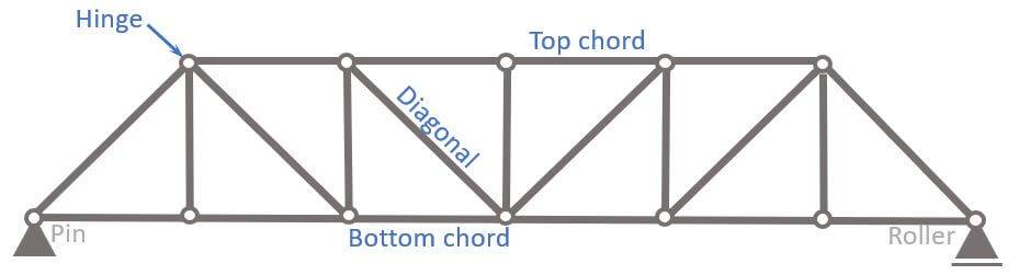
- Top chord
- Bottom chord
- Diagonals
What is the Pratt Truss used for?
Pratt trusses are mainly used as bridge structures of
- railways or
- pedestrian crossings
In most cases, steel is the main material for Pratt trusses, however timber can also be an option.
And often the deck is made from concrete.
Let’s look at the static system to get a better understanding of the structural behaviour of the Howe Truss.🚀🚀
Static System

The static system of the Pratt truss is characterized by having
- hinge connections at all nodes
- a pin and roller support, which makes the system statically determinate. Therefore, the internal forces can be calculated with the 3 equilibrium equations.
Hinges
Most truss structures are designed with hinge connections, mainly due to 2 reasons:
- Easier to calculate: Trusses with hinge connections make the structure statically determinate, which means that the internal forces can be calculated by hand. Especially until advanced Finite element software programs weren’t widely available, this was the main reason for using hinge connections. If fixed connections are used, but no software is available, advanced methods like the method of consistent deformation can be used. However, these methods are complicated and susceptible to calculation failures.
- Cost: Hinge connections are cheaper to build than fixed connections.
It definitely makes sense to be aware of the differences of a truss with hinges and fixed connections. In the picture below, you can see the “normal” Pratt truss with hinge connections.
We summarize the characteristics of the truss with fixed connections a bit further below.
Characteristics
Loads
In most cases, the Pratt truss is used as a bridge structure, where dead and traffic loads are applied on the top or bottom chords.
Support types
1 Pin and 1 Roller support
Reactions
Pin support: Horizontal AH and vertical reaction force AV
Roller support: Vertical reaction force BV
Connection types
Hinge connections: Moment is 0 in hinge connections.
Pratt Truss with fixed connections
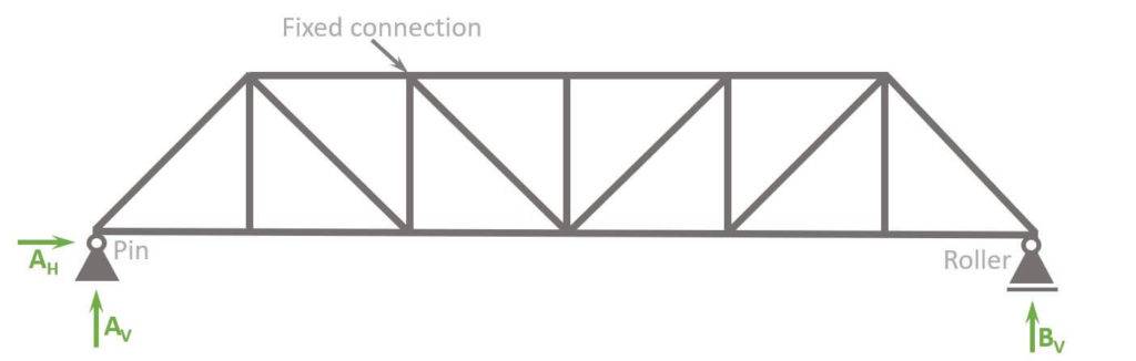
The Pratt truss with fixed connections has the following differences to hinge connections:
- Bending moments in the connections
- More rigidity -> more robustness
- Smaller vertical deflection
Alright, now that we have learned how to set up our static system, we are ready to calculate the internal compression and tension forces of the truss.🎉🎉
Pratt Truss Analysis
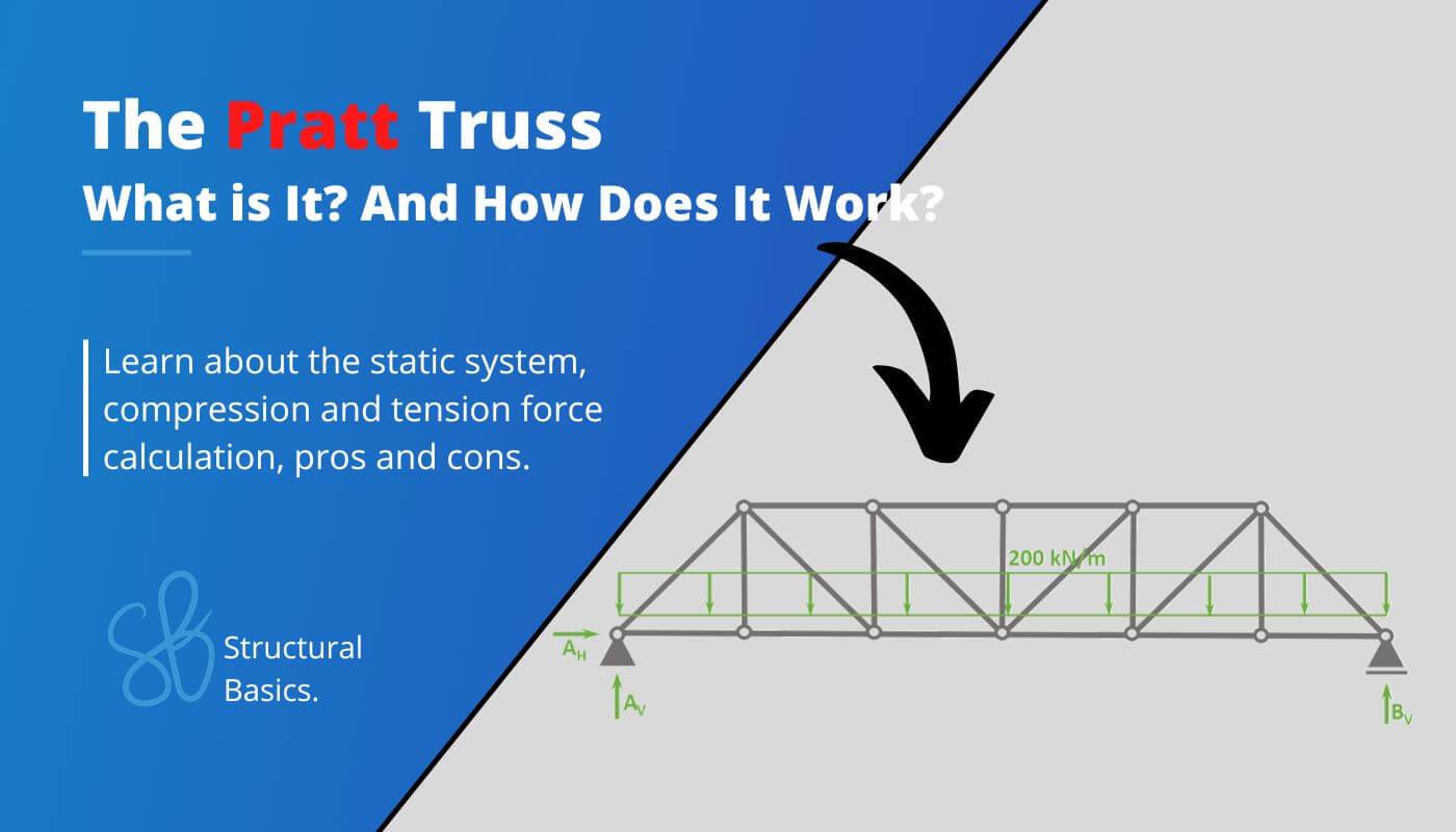
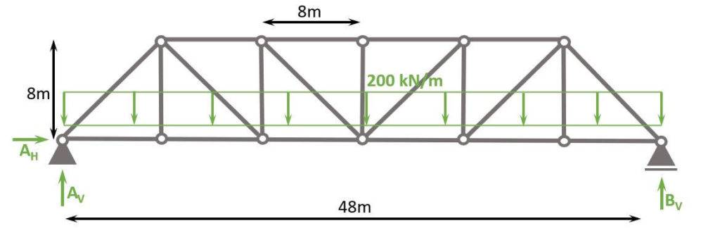
Let’s say our Pratt Truss is a bridge structure. Therefore, the truss is exposed to dead and traffic load mainly on the bridge deck, which transfers the loads to the bottom chord.
We also simplify and say that the design load (Load combination of dead and traffic load) is 200 kN/m to be able to compare the results to the normal forces of the Howe truss.
Check out this article to learn more about the dead load.
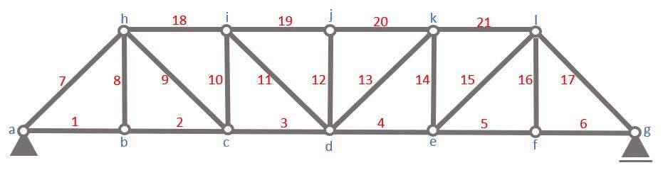
Before we start with the calculations, let’s give the nodes 🔵 and bars 🔴 some indices, so the identification is easier later in the internal force calculation.
To calculate the compression and tension forces of the truss members with the 3 equilibrium equations, we do another approximation.
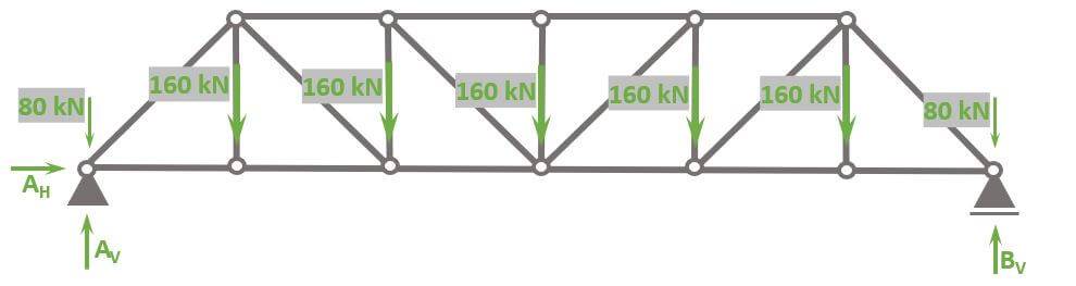
The Line load of 200 kN/m is approximated as point loads in the nodes, because otherwise the bottom chord members would be beams instead of bars, which makes the calculation a lot more difficult.
The point load applied to nodes (a) and (g) is calculated as
$$200 kN/m \cdot 4m = 80 kN$$
while the point loads applied to nodes (b), (c), (d), (e) and (f) is calculated as
$$200 kN/m \cdot 8m = 160 kN$$
Let’s calculate. 🚀🚀
Calculation of Reaction Forces
As the structure is statically determinate, the reaction forces can be calculated with the 3 Equilibrium equations.
In our case, we are calculating the support forces AH, AV and BV.
$\sum H = 0: A_H = 0$
$\sum V = 0: A_V + B_V \, – 2 \cdot 80 \, \mbox{kN} \, – 5 \cdot 160 \, \mbox{kN} = 0 $ -> $V_a = V_b = \frac{2 \cdot 80 + 5 \cdot 160}{2} \mbox{kN} = 480 \mbox{kN}$
$\sum M = 0: M_a = 0$
Calculation of the internal forces
Node a
Alright, now that we know the reaction forces, we can calculate the normal force of the first bar elements 1 and 4.
To do that, we only look at node 1 and its point loads/normal forces AV, 80 kN, N1 and N7.

$$ \alpha = 45° $$
Vertical Equilibrium:
$$ \sum V = 0: A_v – 80 kN + N_7 \cdot sin(\alpha) = 0$$
Let’s solve that for N7.
$$ N_7 = \frac{80 kN – 450 kN}{sin(\alpha)} = -565.69 kN$$
Horizontal Equilibrium:
$$ \sum H = 0: N_7 \cdot cos(\alpha) + N_1 = 0$$
Let’s solve that for N1.
$$ N_1 = – N_7 \cdot cos(\alpha) = 400 kN$$
Node b
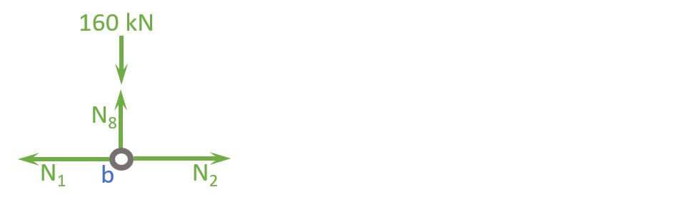
Vertical Equilibrium:
$$ \sum V = 0: N_8 – 160 kN= 0$$
Let’s solve that for N8.
$$ N_8 = 160 kN$$
Horizontal Equilibrium:
$$ \sum H = 0: -N_{1} + N_2 = 0$$
Let’s solve that for N2.
$$ N_{2} = N_1 = 400 kN$$
Node h
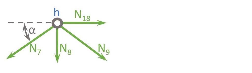
$$ \alpha = 45 ° $$
Vertical Equilibrium:
$$ \sum V = 0: N_8 + N_7 \cdot sin(\alpha) + N_9 \cdot sin(\alpha) = 0$$
Let’s solve that for N9.
$$ N_9 = – N_7 – \frac{N_8}{sin(\alpha)} = 339.41 kN$$
Horizontal Equilibrium:
$$ \sum H = 0: N_{18} – N_7 \cdot cos(\alpha) + N_9 \cdot cos(\alpha) = 0$$
Let’s solve that for N18.
$$ N_{18} = N_7 \cdot cos(\alpha) – N_9 \cdot cos(\alpha)= -640 kN$$
Node c
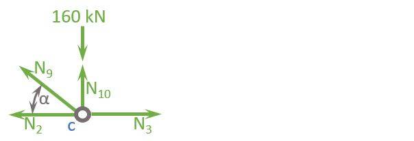
$$ \alpha = 45 ° $$
Vertical Equilibrium:
$$ \sum V = 0: – N_{10} – N_{9} \cdot sin(\alpha) + 160 kN = 0$$
Let’s solve that for N10.
$$ N_{10} = 160 kN – N_{9} \cdot sin(\alpha) = -80 kN$$
Horizontal Equilibrium:
$$ \sum H = 0: – N_{9} \cdot cos(\alpha) + N_{3} – N_{2} = 0$$
Let’s solve that for N3.
$$ N_{3} = N_{2} + N_{9} \cdot cos(\alpha) = 640 kN$$
Node i
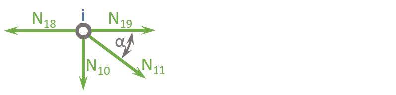
$$ \alpha = 45 ° $$
Vertical Equilibrium:
$$ \sum V = 0: N_{11} \cdot sin(\alpha) + N_{10} = 0$$
Let’s solve that for N11.
$$ N_{11} = -\frac{N_{10}}{sin(\alpha)} = 113.14 kN$$
Horizontal Equilibrium:
$$ \sum H = 0: N_{11} \cdot cos(\alpha) + N_{19} – N_{18} = 0$$
Let’s solve that for N19.
$$ N_{19} = N_{18} – N_{11} \cdot cos(\alpha) = -720 kN$$
Node d
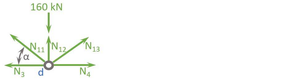
$$ \alpha = 45 ° $$
Vertical Equilibrium:
$$ \sum V = 0: – N_{12} + 160 kN – N_{11} \cdot sin(\alpha) – N_{13} \cdot sin(\alpha) = 0$$
Due to symmetry N13 = N11.
Let’s solve that for N12.
$$ N_{12} = 160 kN – 2 N_{11} \cdot sin(\alpha) = 0$$
Well done! Now we have calculated the normal forces of ALL bars.🎉🎉
What all? But we are missing half of the bars.
Yes! But due to symmetry we know that N1 = N6, N2 = N5, N3 = N4, N7 = N17, N8 = N16, N9 = N15, N10 = N14, N11 = N13, N18 = N21, N19 = N20.
So, to summarize it, a normal force diagram helps to understand how the loads travel through the truss.
Normal force diagram
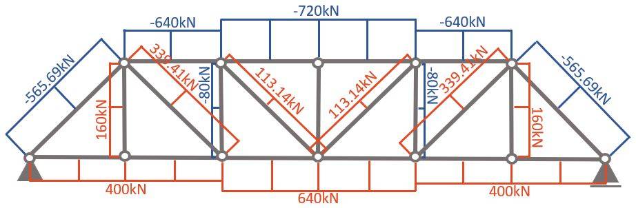
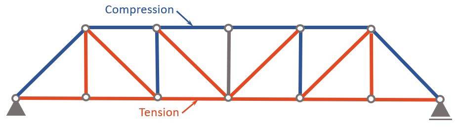
Compression and Tension Members
Now, as you can see in the normal force diagram, some members have a positive (+) and some have a negative (-) normal force.
A negative (-) normal force means that the member is under compression 🔵, while a positive (+) normal force means that the member acts in tension 🔴.
Advantages and Disadvantages
The pros and cons are basically the same as for the Howe truss, because of their similar shape and geometry.
Pros
- Cost-efficient truss system mainly due to its simple design with equal angles which makes it easy to construct
- It’s a lightweight solution for longer spans
- Very durable: Most truss members act mainly in compression or tension (depending on the static system used)
- Equal force distribution to its diagonal and vertical members
Cons
- Takes up more vertical space compared to slab or beam bridges
Conclusion
Now, that you got an overview of the Pratt Truss, and how we calculate its internal forces, you can learn about loads, because every truss is exposed to loads.
Because there are always multiple loads acting on Pratt Trusses, considering these different loads in the structural design is done by setting up Load Combinations with safety factors.🦺
Once all load cases and combinations are set up, the structural elements can be designed. We have already written a guide on how to design a timber truss. Check it out!
I hope that this article helped you understand the Pratt Truss and how to go further from here. In case you still have questions.
Let us know in the comments below ✍️.
Pratt Truss FAQ
The Pratt truss is mainly used for railway and pedestrian bridges. However, it can also be used for roof structures.
A Pratt truss is a structural system which can carry loads efficiently. This means that larger spans are possible with smaller cross-sections than for other structural systems such as the beam.