
As the name implies, a hybrid roof system combines plywood sheathing and wood sub-purlins supported by open web steel joists and joist girders. Hybrid roof systems offer a more sustainable alternative to metal deck systems. In addition, depending on the market, hybrid roofs can be more cost-effective and faster to build than metal deck roofs. This article investigates hybrid roofs under light to heavy uniform and non-uniform snow loads throughout the Mainland U.S. Sheathing thickness, rafter size, and rafter spacing are adjusted accordingly to provide adequate strength and stiffness. The findings are presented in color-coded maps, enabling owners, architects, and engineers to make instant and accurate decisions.
What Is a Hybrid Roof?
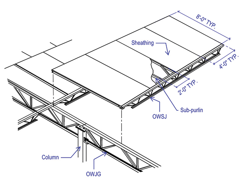
Hybrid roofs consist of wood sheathing panels supported by wood sub-purlins (Figure 1) spaced at two feet on-center (OC). The sheathing and sub-purlin assembly is supported by open web steel joists (OWSJ), equipped with wood nailers to create an essential interface between wood and steel. OWSJs are then supported by open web joist girders (OWJG), which only have nailers in strategic locations to resist lateral loads.
Why a Hybrid Roof?
Hybrid roofs offer a great alternative to metal deck roofs. They are equally durable, produce less carbon footprint, cost less, and can be built faster. In addition, hybrid roofs provide a less expensive roof assembly with a waterproofing membrane above and insulation below, if required. Whereas metal deck has been commonly used when combatting heavy snow, this article highlights the hybrid roof’s ability to support equally significantly high snow loads.
Ground Snow
To design a roof system capable of supporting snow loads, the structural engineer must first identify the ground snow conditions using maps from the building code (ASCE 7-16, Minimum Design Loads and Associated Criteria for Buildings and Other Structures, in the U.S.). For the mainland U.S., the ground snow ranges from 0 – 100 psf, with ground snow increasing from south to north. In some cases, specific states have a significant variation of snow conditions and require micro mapping by county. The Table summarizes the range of ground snow in these seven states based on ASCE 7-16 tabulated values.
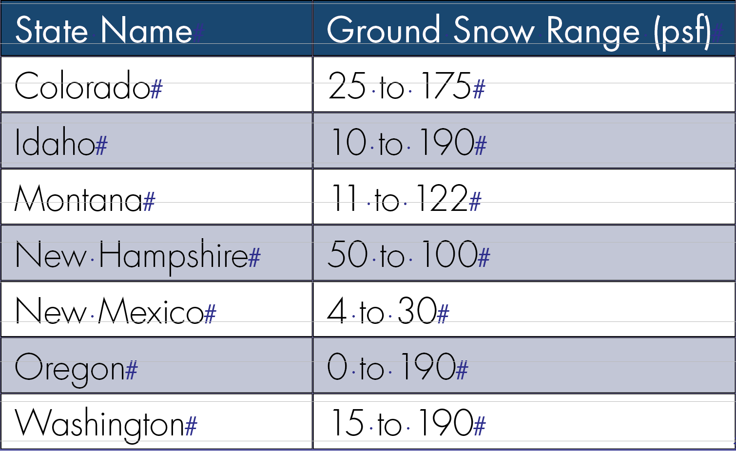
Note that extreme snow regions above 6,000-foot elevation and ski areas are excluded and beyond the scope of this article.
Roof Snow Load
This article considers two types of roof snow loads: uniform roof snow load and snow drift. Uniform snow load occurs when snow accumulates upon a flat, wide-open roof, free from obstruction. The relationship between ground snow and uniform roof snow load is provided by Equation 1.
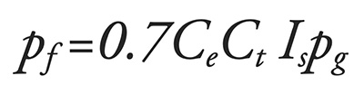
where: pf = flat roof snow load
Ce = exposure factor
Ct= thermal factor
Is = importance factor
pg = ground snow load
Typically, big-box projects are developed in an open area (Ce=1.0) and are equipped with heating systems (Ct=1.0). Therefore, this article assumes 70% of the ground snow is used to establish uniform roof snow load.
Non-uniform snow drift occurs when there is a vertical obstruction the wind can accumulate the snow against, depending on the type of obstruction it encounters. Figure 2 shows common examples of snow drift accumulation, such as roof parapets, rooftop units, high roofs, canopies, etc.
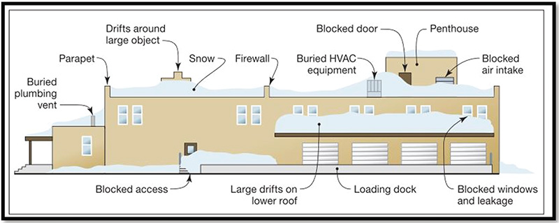
Specifically, this article examines a universally prevalent cause of snow drift: accumulation against parapets. A parapet height of 4 feet 8 inches accounts for fall protection, roof slopes, and roofing/insulation assembly above the wood structural sheathing. Based on this parapet height, the extent of the snow drift zone is calculated to be 12 to 25 feet away from the perimeter of the roof. The band of snow drift becomes narrower around the roof perimeter with the increase in ground snow. Other forms of snow drift are left to the engineer to address per project-specific design requirements.
Design of Wood Structural Panel for Big-box Buildings
Hybrid roofs are typically constructed with 5-ply plywood, a wood structural panel (WSP) made from thin layers of wood stacked and rotated 90 degrees against each other. Another common option is the Oriented Strand Board (OSB), a WSP made from multiple strand layers assembled in different orientations packed and compressed together. Although these two types differ in manufacturing, they share the same material characteristics and design function. The WSP selection is generally subject to availability and client-specific request. For this article, OSB is considered. Sheathing thickness varies from a half inch for regions with zero to light snow loads and can be increased to seven-eighths of an inch for heavy snow areas.
The WSP is designed for bending (strength) and deflection (serviceability). Primarily, the panel’s nominal design capacity is computed with uniform loads and is later adjusted to account for external factors such as load duration, moisture, temperature, and panel size.
With the typical panel size being 4 x 8 feet, OWSJs are spaced 8 feet apart, and sub-purlins are spaced at 2 feet OC, as shown in Figure 1. The panel’s longitudinal axis is parallel to the sub-purlin; thus, a two-span condition is appropriate when designing the sheathing.
Equation 2 is used to determine the bending capacity:
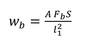
where: wb = uniform load based on bending strength (psf)
FbS = design bending strength capacity (lb-in./ft), determined from AWC 2018 Manual for Engineered Wood Construction (AWC-M) Table M9.2-1
l1 = center-to-center support span (in)
A = 96, for two-span conditions
The nominal bending capacity is then multiplied with adjustment factors as provided in Equation 3:
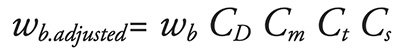
where: wb = uniform load based on bending strength (psf)
CD = load duration factor
CM = wet service factor
Ct = temperature factor
Cs = panel size factor
For snow loading, CD= 1.15. For a conditioned interior, Cm = 1 and
Ct = 1. The sheathing panels are placed parallel to the sub-purlin (Cs = 1).
Equation 4 is used to determine the deflection under uniform load:
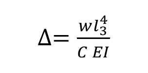
where: ∆ = deflection (in.)
w = uniform load (psf)
EI = design bending stiffness capacity (lb-in2/ft), acquired using AWC-M Table M9.2-4
l3 = l2 + SW
where: SW = support-width factor = 0.25 inches for two-inch nominal lumber framing, = 0.625 inches for four-inch nominal lumber framing.
l2 = center-to-center support span minus support width (in)
C = 2220 for two-span conditions
Once computed per above, the deflection values must satisfy the roof deflection criteria.
Design of Wood Structural Sub-purlins
The sub-purlin is designed for bending, shear (strength), and deflection (serviceability), with the nominal capacity modified with applicable adjustment factors. The typical sub-purlin size in light snow regions is 2 x 4 inches and is spaced at 2 feet OC. The rafter size can be increased to 3 x 4, 3 x 6, 4 x 4, or 4 x 6 inches, and the spacing can be reduced to 1 foot OC as needed for buildings in heavy snow areas.
Structural Capacities of Different Roof Assemblies
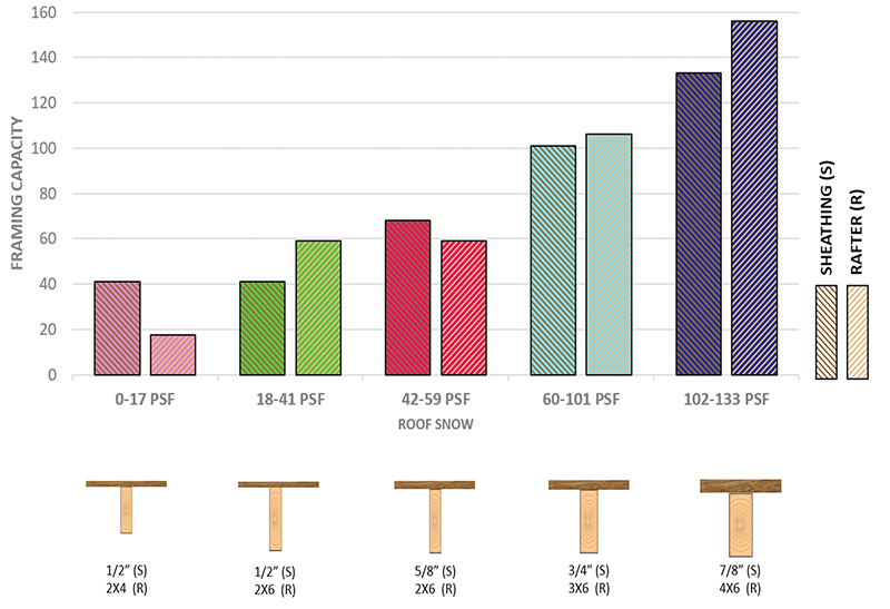
This article examines the capacities of different combinations of sheathings and sub-purlins, provided in Figure 3. The vertical axis indicates each element’s uniform roof snow load capacity, and the horizontal axis shows the load range that the entire assembly can support. The range is based on the lower capacity between the sheathing and sub-purlin. Selecting different sheathing thicknesses and sub-purlin cross sections for each assembly allows for the ability to match the load-carrying capacities for both elements as much as possible.
Wood-Assembly Map for the Mainland U.S.
As discussed before, the mainland U.S. has a vast range of snow loading. In the color-coded map in Figure 4, regions are grouped in ranges of roof snow loads. The colors presented in the map are to be used in tandem with the wood assemblies’ chart in Figure 3.
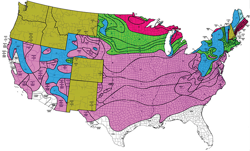
An example of how to use color-coded maps is:
Based on the map in Figure 4, the state of Kansas, represented in purple, has roof snow loads ranging from 10 psf to 17 psf. Referring to Figure 3, the purple color represents an assembly for 0-17 psf roof snow load. Therefore, the roof assembly size for projects in Kansas would be ½-inch sheathing and a 2-inch x 4-inch rafter.
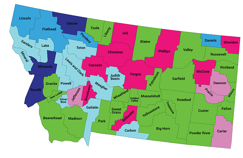
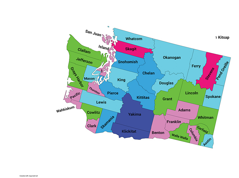
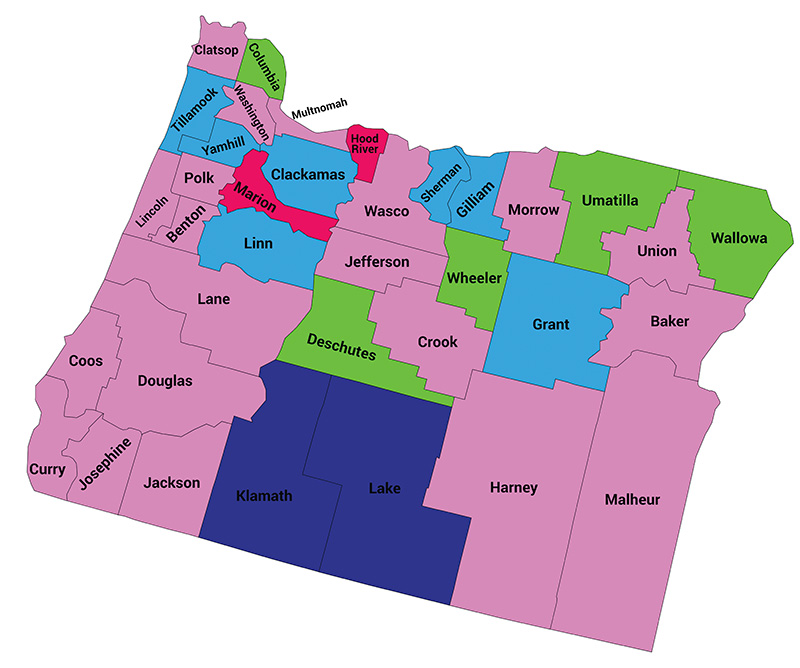
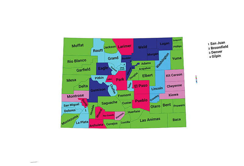
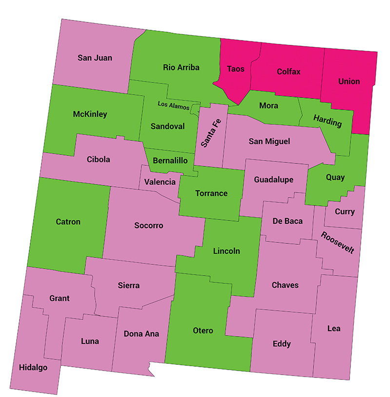
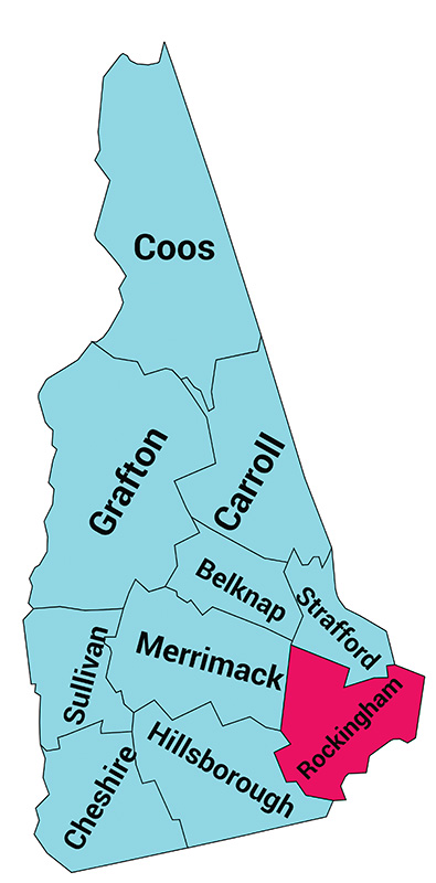
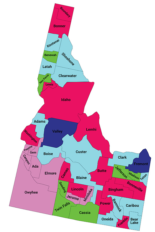
As previously discussed and summarized in the Table, seven states represented with dark yellow have a significant ground and, therefore, roof snow variance. Individual maps are shown for each of these seven states in Figures 5a thru 5g. The areas of the country in dark blue fall under the case study category where the ground snow is not documented and requires a site-specific study.
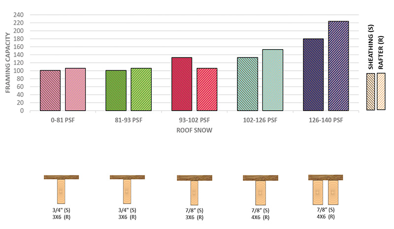
Roof Framing Assemblies for Non-Uniform Snow
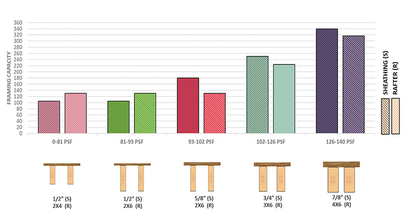
In addition to designing for uniform roof snow, special consideration is taken for non-uniform snow (snow drift). As previously mentioned, the snow drift accumulates in a 12- to 25-foot band around the perimeter of the building, accumulating against a 4-foot 8-inch-high parapet. Figure 6 presents the potential framing assemblies for differing snow drift ranges. Note that for snow drift ranging between 126 to 140 psf, the rafter spacing of 2 feet OC would not work, and the spacing of the rafters would be reduced to 1 foot. As an alternative, roof framing assemblies shown in Figure 7 can also be used in the snow drift zone, and the sub-purlins are to be spaced at 1 foot OC. With the latter arrangement, it would be possible to maintain sheathing thickness and sub-purlin size. The only change would be to double up the sub-purlins in some or all the snow drift zone.
Sustainability
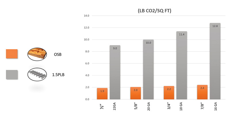
Since wood is an eco-friendly material, the production of wood roofs results in far lower carbon emissions when compared to 1.5 PLB-type metal decks (Figure 8). In addition, wood is a renewable resource as it can be grown indefinitely and can be replaced.
Constructability
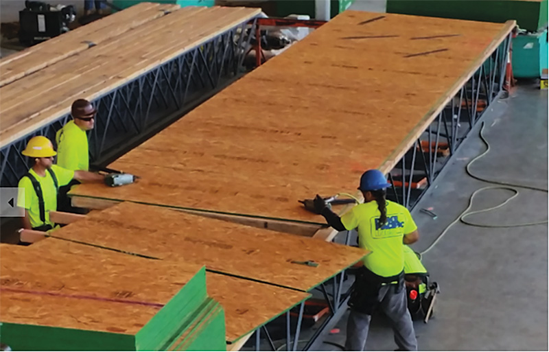
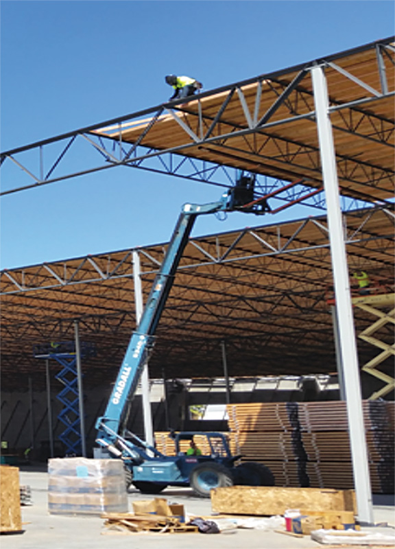
The hybrid roof system utilizes a panelized construction sequence. A bay consisting of joists, rafters, and sheathing is first assembled on the ground (Figure 9). The panelized joist is then lifted and installed onto the roof. The process repeats until the roof’s completion (Figure 10). Having most of the roof’s construction occur on the ground is more efficient. In addition, it decreases the job’s complexity, where construction workers are safe from elevated falls and have better access to assemble each bay.
Conclusion
This article demonstrates the hybrid roof system’s versatility in supporting a wide range of snow loads throughout the mainland U.S. The benefits extend to providing a durable, cost-effective, and sustainable alternative to other structural roof systems.