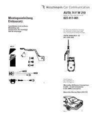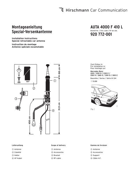
AUTA 4000 F 410 L_0613.pdf - Hirschmann Car Communication
AUTA 4000 F 410 L_0613.pdf - Hirschmann Car Communication
AUTA 4000 F 410 L_0613.pdf - Hirschmann Car Communication

Sie wollen auch ein ePaper? Erhöhen Sie die Reichweite Ihrer Titel.
YUMPU macht aus Druck-PDFs automatisch weboptimierte ePaper, die Google liebt.
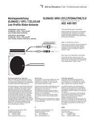
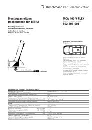
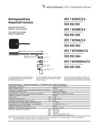
Montageanleitung<br />
Spezial-Versenkantenne<br />
Installation instructions<br />
Special retractable car antenna<br />
Instruction de montage<br />
Antenne spéciale escamotable<br />
<br />
Lieferumfang<br />
Antenne<br />
Zubehör<br />
Halter<br />
HF-Kabel<br />
50°<br />
450 cm<br />
<br />
<br />
<br />
31,5 cm 88 cm<br />
Scope of delivery<br />
Antenna<br />
Accessories<br />
Bracket<br />
RF-cable<br />
<strong>AUTA</strong> <strong>4000</strong> F <strong>410</strong> L<br />
Bestell-Nr. / Ord. code / N° de cde.<br />
920 772-001<br />
Zum Einbau in:<br />
For installation in:<br />
Pour montage sur:<br />
Mercedes Benz<br />
200 / 200 D / 230 E /<br />
250 D / 260 E / 300 D / 300 E<br />
Baureihe / Series / Série W 124<br />
→ 8.88<br />
Fig. 1<br />
Gamme de livraison<br />
Antenne<br />
Accessoires<br />
Support<br />
Câble H.F.
Fig. 2<br />
2<br />
50°<br />
Fig. 3<br />
Fig. 4<br />
495 750-305<br />
blank<br />
bare<br />
non-traité<br />
Fig. 4<br />
Fig. 5<br />
Fig. 4<br />
Fig. 6<br />
Fig. 4<br />
Fig. 7<br />
Fig. 4<br />
Fig. 8<br />
Fig. 4<br />
Fig. 9<br />
Fig. 4<br />
Fig. 10
D GB F<br />
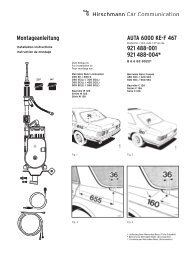
Einbauanleitung<br />
Der Einbau der Versenkantenne<br />
<strong>AUTA</strong> <strong>4000</strong> F <strong>410</strong> L erfolgt bei den angegebenen<br />
Mercedes-Benz-Modellen in den linken<br />
hinteren Kotflügel.<br />
• Im Kofferraum die linksseitige Auskleidung<br />
entfernen. Bei Wagen mit Anhängervorrichtung<br />
vorher die Strebe abschrauben.<br />
Für Kabelverlegung hintere Sitzbank und<br />
-kissen ausbauen.<br />
• An der Einbaustelle nach Fig. 1 bzw. 2 die<br />
beiliegende Schablone anlegen, das<br />
Karosserieloch anzeichnen und maßhaltig<br />
einarbeiten (Toleranz ±0,2 mm). Zum<br />
Schutz des Lackes vorher mit Klebeband<br />
abkleben. Die Bohrung entgraten, zum<br />
Schutz gegen Korrosion die blanke Kante<br />
mit Grundlack bestreichen und trocknen<br />
lassen.<br />
• In der Zwischenzeit das Antennenkabel<br />
zusammen mit dem bereits verlegten Leitungssatz<br />
durch die Mehrfachtülle unter<br />
die Rücksitzbank, von dort unter der linken<br />
Einstiegsleiste, im Kabelkanal bis zum<br />
Fahrersitz nach vorne und von dort zum<br />
Empfänger verlegen und einstecken (evt.<br />
Durchziehdraht verwenden).<br />
• Das Antennenkabel ist geräteseitig mit<br />
einem abwinkelbaren Stecker versehen.<br />
Dadurch kann der Stecker je nach Bedarf<br />
gerade oder als Winkelstecker verwendet<br />
werden. Das Abbiegen über den Führungsrücken<br />
bitte nur von Hand durchführen,<br />
damit Kabel und Stecker nicht verletzt<br />
werden (Fig. 3).<br />
• Die Dichttülle von oben in das Karosserieloch<br />
einsetzen (Fig. 4 und 5). Dies muss<br />
am unteren Einstich der Dichttülle erfolgen.<br />
Der obere Einstich liegt gut sichtbar über<br />
der Karosserie (Fig. 4 und 6).<br />
• Das Antennenkabel an der Antenne festschrauben,<br />
den Kugelstutzen mit etwas<br />
Antennenfett bestreichen (<strong>AUTA</strong> 115) und<br />
die Antenne von unten in die bereits eingesetzte<br />
Dichttülle eindrücken (Fig. 4).<br />
Die Antenne mit Halter am Schutzrohr<br />
gegen das vorhandene Langloch am<br />
Karosseriesteg anschrauben (Fig. 3 und 9).<br />
• Teleskop ausziehen, Neigung kontrollieren;<br />
danach Schrauben am Halter fest anziehen.<br />
• Die Kappe von oben auf die Dichttülle aufsetzen,<br />
leicht nachdrücken, bis sie einrastet<br />
und an der Karosserieoberfläche gleichmäßig<br />
anliegt (Fig. 4, 7 und 8).<br />
• Das Masseband an vorhandenem Loch an<br />
der Verstrebung festschrauben, Anlagefläche<br />
vorher blank schaben und einfetten<br />
(Fig. 3 und 9).<br />
• Auskleidung im Kofferraum und Rücksitz<br />
wieder einbauen.<br />
• Das Teleskop ist mit einem Stülpknopf<br />
(720 978-002) ausgerüstet (Fig. 3) und<br />
kann von Hand gegriffen und ausgezogen<br />
werden. Mit abgenommenem Stülpknopf<br />
kann das Teleskop vollständig versenkt<br />
und nur mit dem Schlüssel ausgezogen<br />
werden (Fig. 10).<br />
• Achten Sie bitte darauf, dass nach dem<br />
Einbau der Antenne der Empfänger nachgetrimmt<br />
wird. Am Antenneneingang des<br />
Gerätes ist ein von außen bedienbarer<br />
Trimmer eingebaut.<br />
Installation instructions<br />
Installation of the retractable antenna<br />
<strong>AUTA</strong> <strong>4000</strong> F <strong>410</strong> L left-side in the rear<br />
wing of the stated Mercedes-Benz cars.<br />
• Remove left-side lining in the luggageboot.<br />
For cars with trailer coupling, unscrew<br />
previously the support. For cable laying<br />
detach the back seat, too.<br />
• Apply the attached drilling template and<br />
mark the installation point acc. to fig. 1 or 2,<br />
resp., cover the paintwork with protective<br />
tape, and drill a hole (tolerance ±0,2 mm).<br />
Remove the burr, spread the bare edge<br />
with primer to protect against corrosion<br />
and allow to dry.<br />
• In the meantime pass the antenna cable<br />
through the multiple grommet under the<br />
back seat, then along the left edge in the<br />
cable tunnel to the front and plug-in to<br />
the radio receiver (if necessary use a<br />
draw wire).<br />
• At the radio end the antenna cable is fitted<br />
with a plug that can be angled, so it can be<br />
used straight or, if necessary, as an angled<br />
plug. Please bend by hand only to avoid<br />
any damage of cable or plug (fig. 3).<br />
• Insert the sealing sleeve from top into the<br />
car body hole (fig. 4 and 5). Take care<br />
that the lower recess of the sleeve fits to<br />
the body sheet, so the upper recess<br />
should be clearly visible above the car<br />
body (fig. 4 and 6).<br />
• Tighten the antenna cable to the antenna<br />
case, spread the spherical antenna head<br />
with some special grease (<strong>AUTA</strong> 115) and<br />
push the antenna from below through the<br />
sleeve inserted before (fig. 4).<br />
Fix the antenna with bracket at the protective<br />
tube to the existing oblong hole in<br />
the car body bar (fig. 3 and 9).<br />
• Extend the telescope, check the angle,<br />
then tighten the screws at the bracket.<br />
• Apply the cap on top of the sleeve and<br />
press until snapping-on and fitting tightly<br />
to the car body surface (fig. 4, 7 and 8).<br />
• Fix the earthing tape to the existing hole<br />
at the brace. Previously bare the connecting<br />
surface and spread with grease<br />
(fig. 3 and 9).<br />
• Replace lining and back seat.<br />
• On top the telescope is provided with a<br />
plastic knob (720 978-002) as shown in<br />
fig. 3, that can be extended by hand. If this<br />
knob is detached, the telescope can – after<br />
retraction – only be extended by a special<br />
key (fig. 10).<br />
• Please make sure that the radio will be<br />
tuned again after the antenna has been<br />
installed. On the antenna input of the<br />
receiver there is an incorporated trimmer<br />
that can be operated from outside.<br />
• With antenna fully extended select a weak<br />
station in the medium wave band (approx.<br />
1100 kHz or acc. to the instructions of the<br />
manufacturer of the radio) and set the<br />
maximum volume by means of the trimmer.<br />
• The lowest tube must be always fully extended<br />
in order to ensure a good reception.<br />
Instruction de montage<br />
L'installation de l'antenne escamotable<br />
<strong>AUTA</strong> <strong>4000</strong> F <strong>410</strong> L se fait dans les modèles<br />
indiqués de Mercedes-Benz sur l'aile arrière<br />
gauche.<br />
• Enlever le revêtement du côté gauche du<br />
coffre. Seulement pour les véhicules possédant<br />
un dispositif pour remorque, dévisser<br />
auparavant l'entretoise. Démonter la banquette<br />
et coussin arrière pour la pose des<br />
câbles.<br />
• A l'emplacement du montage, placer le<br />
gabarit joint selon la fig. 1 resp. 2 marquer<br />
le perçage de la carrosserie et percer<br />
selon les dimensions prescriptes (tolérance<br />
±0,2 mm). Pour protéger la laque, coller<br />
auparavant un ruban adhésif. Supprimer<br />
les bavures du perçage, enduire le bord<br />
mis à nu de laque de fond pour protéger<br />
contre la corrosion et laisser sécher.<br />
• Entre-temps, poser le câble d'antenne<br />
avec le jeu de câble déjà mis par le passecâble<br />
multiple sous la banquette arrière,<br />
de là, vers l'avant sous le rebord d'accès<br />
gauche en tunnel de câble jusque devant<br />
le siège du conducteur et à partir de là, au<br />
récepteur et enficher (au besoin utiliser<br />
du fil déroulable).<br />
• Le câble d'antenne est pourvu sur le côté<br />
de l'appareil d'une connection à fiche pliable.<br />
De ce fait, le connecteur peut être<br />
utilisé si besoin est, droit ou comme fiche<br />
coudée. Veuillez ne le tordre que manuellement<br />
par dessus le tube conducteur,<br />
afin que câble et fiche ne soit pas endommagés<br />
(fig. 3).<br />
• Placer la manchette d'en haut dans le<br />
perçage de la carrosserie (fig. 4 et 5).<br />
Ceci doit être effectué à l'encoche<br />
inférieure de la manchette. La fente<br />
supérieure est bien visible au-dessus de la<br />
carrosserie (fig. 4 et 6).<br />
• Visser à fond le câble d'antenne à l'antenne,<br />
enduire d'un peu de graisse le joint à bille<br />
(<strong>AUTA</strong> 115) et appuyer l'antenne du dessous<br />
dans la manchette déjà placée (fig. 4).<br />
Visser l'antenne avec le support au tube<br />
contre le trou longitudinal existant à la<br />
travers de carrosserie (fig. 3 et 9).<br />
• Sortir le télescope, contrôler l'inclinaison;<br />
ensuite serrer à fond les vis au support.<br />
• Mettre le capuchon d'en haut sur la manchette,<br />
appuyer légèrement, jusqu'à ce<br />
qu'il s'encliquetique et se trouve bien<br />
placé (fig. 4, 7 et 8).<br />
• Visser à fond la bande de mise à la masse<br />
au perçage existant à l'entroise, gratter à<br />
nu avant la surface et graisser (fig. 3 et 9).<br />
• Remettre le revêtement du coffre et la<br />
banquette arrière.<br />
• Le télescope est équipé d'un bouton à<br />
retournement (720 978-002) (fig. 3) et<br />
peut être manipulé et sorti manuellement.<br />
Le télescope peut être complètement<br />
noyé avec le bouton à retournement enlevé<br />
et être seulement sorti avec la clé<br />
(fig. 10).<br />
• Veuillez faire attention à ce que le récepteur<br />
soit réadapté, après la pose de l'antenne.<br />
3
• Bei ganz ausgezogener Antenne einen<br />
schwach einfallenden Sender im Mittelwellenbereich<br />
(ca.1100 kHz bzw. nach Angaben<br />
des Geräteherstellers) einstellen und<br />
mit dem Antennentrimmer größte Lautstärke<br />
einstellen.<br />
• Das unterste Rohr der Antenne muss<br />
stets vollständig ausgezogen werden. Nur<br />
so ist ein einwandfreier Empfang gewährleistet.<br />
Reinigen Sie Ihre Antenne von Zeit zu Zeit<br />
von anhaftendem Straßenstaub. Verwenden<br />
Sie nur ganz wenig von unserem Spezialfett<br />
in Tuben <strong>AUTA</strong> 235, oder benutzen Sie<br />
unser Autoantennen-Pflegetüchlein <strong>AUTA</strong><br />
135, das gleichzeitig reinigt und fettet.<br />
Ersatzteile bitte unter den angegebenen<br />
Nummern bestellen.<br />
Technische Änderungen vorbehalten.<br />
Bestimmungsgemässer Gebrauch:<br />
Dieses Produkt ist ausschliesslich für den<br />
Verbau in Automobilen bestimmt und dient<br />
zum Senden bzw. Empfangen von Funksignalen<br />
im jeweils definierten Frequenzbereich.<br />
Dieses Produkt ist nach seiner Verwendung<br />
entsprechend den aktuellen Entsorgungsvorschriften<br />
Ihres Landkreises / Landes /<br />
Staates als Elektronikschrott einer geordneten<br />
Entsorgung zuzuführen.<br />
Die beschriebenen Leistungsmerkmale sind nur<br />
dann verbindlich, wenn sie bei Vertragsabschluss<br />
ausdrücklich vereinbart wurden. Diese<br />
Druckschrift wurde von <strong>Hirschmann</strong> <strong>Car</strong><br />
<strong>Communication</strong> GmbH auf Übereinstimmung<br />
mit den beschriebenen Antennen und Antennenzubehör<br />
(Kabel, Stecker etc.) geprüft.<br />
Dennoch können Abweichungen hinsichtlich<br />
der Richtigkeit oder Genauigkeit nicht ausgeschlossen<br />
werden, sodass <strong>Hirschmann</strong> für<br />
die vollständige Übereinstimmung keine<br />
Gewähr übernimmt.<br />
<strong>Hirschmann</strong> behält sich das Recht vor, den<br />
Inhalt dieser Druckschrift ohne Ankündigung<br />
zu ändern.<br />
D<br />
<strong>Hirschmann</strong> <strong>Car</strong> <strong>Communication</strong> GmbH<br />
Stuttgarter Strasse 45 - 51<br />
D-72654 Neckartenzlingen<br />
Tel +49-7127-14-1873<br />
Fax +49-7127-14-1428<br />
E-mail: amsales@hirschmann-car.com<br />
024 549-000-09-0613-N<br />
Printed in Europe . Imprimé en Europe<br />
From time to time, clean the telescope of<br />
adhering road dust. Use only a little of our<br />
special aerial grease <strong>AUTA</strong> 235, supplied in<br />
tubes, or our car aerial tissue <strong>AUTA</strong> 135 for<br />
both, cleaning and greasing.<br />
Please state order numbers when ordering<br />
spare parts.<br />
Right of modification reserved.<br />
Normal Use:<br />
This product is exclusively designed for the<br />
installation in vehicles and serve for the<br />
emission and reception of radio signals in<br />
each defined frequency range.<br />
After its use, this product has to be processed<br />
as electronique scrap to a proper disposal<br />
according to the prevailing waste disposal<br />
regulations of your community / district /<br />
country / state.<br />
The performance features described here<br />
are binding only if they have been expressly<br />
guaranteed in the contract. This publication<br />
has been created by <strong>Hirschmann</strong> <strong>Car</strong> <strong>Communication</strong><br />
GmbH according to the best of<br />
our knowledge.<br />
<strong>Hirschmann</strong> reserves the right to change<br />
the contents of this manual without prior<br />
notice.<br />
<strong>Hirschmann</strong> can give no guarantee in respect<br />
of the correctness or accuracy of the<br />
details in this publication.<br />
F<br />
<strong>Hirschmann</strong> <strong>Car</strong> <strong>Communication</strong> S.A.S<br />
84 Bld de la Mission Marchand<br />
F-92400 Courbevoie<br />
Tel +33-1-80 88 51 00<br />
Fax +33-1-80 88 51 01<br />
E-mail: hcc@hirschmann-car.fr<br />
A l'entrée de l'antenne de l'appareil, il est<br />
monté un condensateur de compensation<br />
réglable de l'extérieur.<br />
• Lorsque l'antenne est entièrement sorti,<br />
choisir un émetteur reçu faiblement dans<br />
les ondes moyennes (env. 1100 kHz resp.<br />
selon données du constructeur) et régler<br />
à puissance maximum.<br />
• Le tube le plus bas de l'antenne doit toujours<br />
être sorti complètement. Seulement<br />
de cette façon, il est possible d'avoir une<br />
réception parfaite.<br />
Débarrasser votre antenne des poussières<br />
adhérentes de la rue, de temps en temps.<br />
Utiliser très peu notre graisse spéciale sous<br />
forme de tube <strong>AUTA</strong> 235, ou bien utiliser<br />
notre essuie-antenne-auto <strong>AUTA</strong> 135 qui<br />
nettoie et graisse en même temps.<br />
Veuillez commander les pièces détachées<br />
sous les numéros indiqués.<br />
Sous réserve de modifications techniques.<br />
Utilisation approprié:<br />
Ce produit est fait exclusivement pour<br />
l'utilitsation dans les automobiles et sert<br />
pour l'émission et la réception des signaux<br />
dans la gamme des frequences definie.<br />
Ce produit doit être éliminé en tant que<br />
déchet électronique conformément au réglement<br />
actuel sur l'élimination des déchets de<br />
votre département / région / pays.<br />
La société <strong>Hirschmann</strong> <strong>Car</strong> <strong>Communication</strong><br />
GmbH ne se porte garante de la véracité des<br />
informations techniques que si elles ont été<br />
spécifiées de manière expresse à la signature<br />
du contrat.<br />
Le contenu de ce document a été minutieusement<br />
contrôlé afin de s’assurer qu’il corresponde<br />
bien aux antennes et accessoires<br />
(câbles, connecteurs) décrits. Toutefois,<br />
<strong>Hirschmann</strong> ne peut en aucun cas être tenu<br />
responsable de l’exactitude de ces informations.<br />
<strong>Hirschmann</strong> se réserve le droit de<br />
modifier sans préavis le contenu de ce document.<br />
USA<br />
<strong>Hirschmann</strong> <strong>Car</strong> <strong>Communication</strong>, Inc.<br />
1183 Centre Road<br />
Auburn Hills, MI 48326<br />
Tel +1-248 373 7150<br />
Fax +1-248 276 2350<br />
E-mail: sales@hirschmann-mi.com