AFRTS Defense Media Center Satellite Handbook
AFRTS Defense Media Center Satellite Handbook
AFRTS Defense Media Center Satellite Handbook

You also want an ePaper? Increase the reach of your titles
YUMPU automatically turns print PDFs into web optimized ePapers that Google loves.
<strong>Defense</strong> <strong>Media</strong> <strong>Center</strong> <strong>Satellite</strong> <strong>Handbook</strong> V.3.26<br />
<strong>AFRTS</strong> ®<br />
<strong>Defense</strong> <strong>Media</strong> <strong>Center</strong><br />
<strong>Satellite</strong> <strong>Handbook</strong><br />
Version 3.26<br />
Published May 2010<br />
24-hour a day decoder and dish setup hotline<br />
Commercial (951) 413-2339, or DSN (312) 348-1339<br />
or email technologist@dma.mil<br />
<strong>AFRTS</strong> and the <strong>AFRTS</strong> logos are registered trademarks.
<strong>Defense</strong> <strong>Media</strong> <strong>Center</strong> <strong>Satellite</strong> <strong>Handbook</strong> V.3.26<br />
CHAPTER 1 : POLICY AND PROCEDURES FOR REQUESTING <strong>AFRTS</strong> ®<br />
SATELLITE SERVICE. 1-1<br />
WHO IS <strong>AFRTS</strong> FOR AND WHAT IS ITS MISSION? 1-1<br />
HOW DO I REQUEST <strong>AFRTS</strong> ® SERVICE? 1-2<br />
WHAT DO I DO ONCE I HAVE THE DECODER? 1-2<br />
WHAT CAN THE ORGANIZATION DO IF THERE ARE NOT ENOUGH DOD PEOPLE TO JUSTIFY<br />
A FREE <strong>AFRTS</strong> ® DECODER OR THE FREE DECODER WILL NOT SERVE EVERYONE? 1-3<br />
CAN I LEASE OR RENT A DECODER INSTEAD OF BUYING ONE? 1-4<br />
CAN I BUY MY OWN DECODER? 1-4<br />
REAUTHORIZATION OF DECODERS 1-4<br />
RESALE OF DECODER<br />
CHAPTER 2 : ACTIVATION PROCEDURES AND DATABASE<br />
1-4<br />
MANAGEMENT. 2-5<br />
HOW DO I GET THE DECODER AUTHORIZED? 2-5<br />
HOW LONG DOES IT TAKE TO GET THE DECODER TURNED ON? 2-6<br />
HOW DO YOU KEEP TRACK OF ALL THESE DECODERS? 2-6<br />
WHAT DO I DO IF OR WHEN MY AUTHORIZATION PERIOD IS UP?<br />
WHAT ARE THE DIRECT EXCHANGE (DX) PROCEDURES FOR <strong>AFRTS</strong><br />
2-6<br />
® POWERVU<br />
EQUIPMENT?<br />
WHAT ARE THE REPAIR PROCEDURES FOR CUSTOMER PURCHASED POWERVU<br />
2-6<br />
INTEGRATED RECEIVER DECODER (IRD) EQUIPMENT? 2-9<br />
WHAT ARE THE REPAIR PROCEDURES FOR CUSTOMER LEASED POWERVU INTEGRATED<br />
RECEIVER DECODER (IRD) EQUIPMENT?<br />
WHAT ARE THE REPAIR PROCEDURES FOR DECODERS FROM NAVY SHIPS AND FLEET<br />
2-9<br />
SUPPORT DETACHMENTS? 2-10<br />
CHAPTER 3 : <strong>AFRTS</strong> ® SATELLITE NETWORKS 3-1<br />
INTRODUCTION TO POWERVU 3-1<br />
SATNET C-BAND SATELLITE AND JAPAN/KOREA KU-BAND SERVICES 3-5<br />
SATNET CHANNEL GUIDE 3-6<br />
SATNET EUROPEAN KU-BAND SATELLITE SERVICES 3-8<br />
AFN EUROPE CHANNEL GUIDE 3-8<br />
<strong>AFRTS</strong> ® DIRECT-TO-SAILOR SATELLITE NETWORK (DTS) 3-9<br />
DTS SATELLITE NETWORK ARCHITECTURE 3-10<br />
DTS CHANNEL GUIDE 3-11<br />
THE PENTAGON CHANNEL NETWORK ARCHITECTURE 3-13<br />
THE PENTAGON CHANNEL SATELLITE SETTINGS 3-13<br />
CHAPTER 4 : DIGITAL SATELLITE DOWNLINK RECEPTION 4-1<br />
TYPICAL SATELLITE TVRO EQUIPMENT CONFIGURATION 4-1<br />
GENERAL SATELLITE CONCEPTS 4-1<br />
THE RECEIVE SITE 4-2<br />
RADIO WAVES AND COMMUNICATIONS 4-2<br />
RADIO WAVES 4-2
<strong>Defense</strong> <strong>Media</strong> <strong>Center</strong> <strong>Satellite</strong> <strong>Handbook</strong> V.3.26<br />
Signal Frequency 4-2<br />
Polarization 4-2<br />
ANTENNA REFLECTOR 4-3<br />
AMPLIFIER “LNA/B/C/F” 4-4<br />
LNB PERFORMANCE 4-6<br />
FEEDHORN ASSEMBLY 4-6<br />
FEEDHORN ADJUSTMENTS 4-7<br />
POLARIZATION 4-8<br />
QUALIFICATION OF SATELLITE TERMINALS FOR DIGITAL RECEPTION 4-8<br />
EQUIPMENT NEEDED FOR SATNET C-BAND RECEPTION 4-8<br />
EQUIPMENT NEEDED FOR SATNET KU-BAND RECEPTION 4-9<br />
EQUIPMENT NEEDED FOR DIRECT TO SAILOR (DTS) C-BAND RECEPTION 4-9<br />
SOME NEW TERMS YOU SHOULD KNOW AND UNDERSTAND 4-10<br />
SUN OUTAGES 4-11<br />
RF INTERFERENCE IN DIGITAL NETWORKS 4-11<br />
CURRENT TECHNOLOGY 4-13<br />
ERROR CORRECTION 4-13<br />
REACQUISITION 4-14<br />
CONCEALMENT 4-14<br />
SOURCES OF INTERFERENCE 4-14<br />
Terrestrial Microwave Interference 4-14<br />
Impulse and Ignition Noise 4-15<br />
Aircraft Radar Altimeters/Airport Ground Radar 4-15<br />
Ship-board Radar 4-16<br />
Commercial Microwave Ovens 4-16<br />
Walkie-Talkies 4-16<br />
Cell Phones 4-16<br />
Random RFI (Fluorescent and Sodium Vapor Lamps, Lightning) 4-16<br />
PROTECTION FROM INTERFERENCE 4-17<br />
Selecting a site 4-17<br />
Saturation and Compression 4-17<br />
Out-of-band Filtering 4-17<br />
RFI (Radio Frequency Interference) Fencing 4-17<br />
Earth Berms 4-18<br />
SUMMARY<br />
CHAPTER 5 PROCEDURES FOR FINDING THE <strong>AFRTS</strong><br />
4-18<br />
® DIGITAL<br />
SATELLITE SIGNALS 5-1<br />
Step One: IRD Authorization 5-1<br />
Step Two: Finding a Clear line of Sight 5-1<br />
Step Three: Connecting the Antenna and Receiver 5-2<br />
Step Four: Locating the <strong>Satellite</strong> 5-5<br />
Step Five: Peaking the Antenna 5-6<br />
Step Six: Troubleshooting 5-7<br />
DECODER SETUP INSTRUCTIONS SCIENTIFIC ATLANTA POWERVU (MODEL 9223) 5-9<br />
DECODER SETUP INSTRUCTIONS SCIENTIFIC ATLANTA POWERVU (MODEL 9234) 5-11
<strong>Defense</strong> <strong>Media</strong> <strong>Center</strong> <strong>Satellite</strong> <strong>Handbook</strong> V.3.26<br />
DECODER SETUP INSTRUCTIONS SCIENTIFIC ATLANTA POWERVU (MODEL 9834 AND<br />
9835) 5-15<br />
REMOTE CONTROL PROBLEMS 5-21<br />
RECEIVER PROBLEMS 5-21<br />
CHAPTER 6 : DISTRIBUTION OF MULTIPLE VIDEO AND AUDIO SERVICES<br />
6-22<br />
I. DOD CATV PERFORMANCE SPECIFICATIONS AND TESTING PROCEDURES 6-22<br />
a. Assumptions regarding DOD Cable Systems: 6-22<br />
b. System Characteristics: 6-23<br />
II. DISCUSSION 6-23<br />
a. Authorization 6-24<br />
b. Signal Leakage 6-24<br />
c. Signal Quality 6-24<br />
d. System Constraints 6-25<br />
III. TESTING PROCEDURES. 6-26<br />
APPLICABILITY OF TESTS 6-26<br />
SCHEDULING OF TESTS 6-27<br />
DIGITAL TELEVISION 6-27<br />
IV. OUT OF CONUS CATV 6-28<br />
V. COMMERCIAL CATV. 6-28<br />
CHAPTER 7 : RADIO AND TELEVISION CUEING 7-29<br />
AFN BROADCAST CENTER 7-29<br />
Normal Programming: 7-29<br />
Live and Quick Turn-Around Programming: 7-29<br />
ENCODER INSTALLATION AND OPERATION 7-2<br />
DECODER INSTALLATION AND OPERATION 7-5<br />
CONTROLS AND INDICATORS 7-6<br />
1644 RELAY CARD 7-7<br />
CHAPTER 8 : DATACASTING 8-1<br />
TECHNOLOGY DESCRIPTION 8-1<br />
<strong>AFRTS</strong> ® INTERNATIONAL POWERVU DATACASTING CAPABILITIES 8-1<br />
64 KBPS HIGH SPEED DATA CHANNEL 8-3<br />
EQUIPMENT REQUIREMENTS 8-4<br />
MULTIPLEXER CONFIGURATION 8-5<br />
CBD (HARDWARE,CTS/RTS) FLOW 8-6<br />
SR-8 COMMANDS 8-13<br />
SR-8 SETUP 8-13<br />
1.544 MBPS HIGH SPEED DATA CHANNEL 8-14<br />
Configuration 8-14<br />
Cabling and Pin outs 8-15<br />
DATACASTING ON DTS (128 KBPS HIGH SPEED DATA CHANNEL) 8-15<br />
CONFIGURATION 8-16<br />
CABLING AND PIN OUTS 8-17<br />
1.544 MBPS AND 128 KBPS HIGH SPEED DATA TROUBLESHOOTING GUIDE 8-17
<strong>Defense</strong> <strong>Media</strong> <strong>Center</strong> <strong>Satellite</strong> <strong>Handbook</strong> V.3.26<br />
IRD CONTROL AND POLLING FROM A REMOTE LOCATION 8-18<br />
CHAPTER 9 : NEWSBOSS NETWORK ALERT SYSTEM (NAS) 9-1<br />
WHAT IS NEWSBOSS? 9-1<br />
WHAT IS NAS? 9-1<br />
CHAPTER 10 : CLOSED CAPTION SERVICE<br />
CHAPTER 11 : <strong>AFRTS</strong><br />
10-1<br />
® DECODER OPERATING SYSTEM DOWNLOAD<br />
PROCEDURES 11-1<br />
9234 DECODERS 11-1<br />
9832 DECODERS 11-2<br />
9223 DECODERS 11-2<br />
HOW CAN I TELL IF I NEED AN OS DOWNLOAD? 11-2<br />
HOW TO READ POWERVU DECODER TIDS 11-3<br />
APPENDIXES 1<br />
APPENDIX A: VIRTUAL CHANNEL LISTINGS 2<br />
AFN-BC (California) Error! Bookmark not defined.<br />
AFNE (Europe) Error! Bookmark not defined.<br />
AFN (Pacific) Error! Bookmark not defined.<br />
DTS (Navy) Error! Bookmark not defined.<br />
AFN POWERVU SERVICES DETAIL ERROR! BOOKMARK NOT DEFINED.<br />
1. AFN-BC (California) Error! Bookmark not defined.<br />
2. AFNE (Europe) Error! Bookmark not defined.<br />
3. AFN (Pacific) Error! Bookmark not defined.<br />
4. DTS (Navy) Error! Bookmark not defined.<br />
AFNE (Europe) Channel Guide 56<br />
APPENDIX B: RF LINK BUDGETS 57<br />
Typical SATNET C-Band Link Budget 58<br />
Typical SATNET Ku-Band Link Budget 59<br />
DTS Link Calculations 60<br />
APPENDIX C: DISH POINTING DATA (USING MAGNETIC NORTH) AUG 2007 11<br />
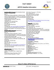
APPENDIX D <strong>AFRTS</strong> SATELLITE INFORMATION 19<br />
<strong>AFRTS</strong> SatNet Service 19<br />
NewSkies NSS-9 (C-band) (dual transponders) 19<br />
NewSkies NSS-6 (Ku-band) (dual transponders) 19<br />
INTELSAT 10-02 (South America, Africa, and Atlantic Ocean Region) 19<br />
IntelSat Galaxy 28 (United States/Central America/Caribbean) 20<br />
HOTBIRDS 6 & 9 (Europe) 20<br />
Direct To Sailor (DTS) Service 21<br />
INTELSAT 701 (Pacific Ocean) 21<br />
INTELSAT 906 (Indian Ocean and Persian Gulf) 21<br />
New Skies NSS-7 (Atlantic Ocean and Mediterranean Sea) 21<br />
IntelSat 707 C Band Domestic to Clarksburg 22<br />
AMC-1 Ku Band (The Pentagon Channel) 22<br />
APPENDIX E: PV CONNECT DECODER AUTHORIZATION PROCEDURES 23
<strong>Defense</strong> <strong>Media</strong> <strong>Center</strong> <strong>Satellite</strong> <strong>Handbook</strong> V.3.26<br />
INDEX 1
<strong>Defense</strong> <strong>Media</strong> <strong>Center</strong> <strong>Satellite</strong> <strong>Handbook</strong> V.3.26<br />
Chapter 1 : Policy and Procedures for Requesting <strong>AFRTS</strong> ®<br />
<strong>Satellite</strong> Service.<br />
Who is <strong>AFRTS</strong> for and what is its mission?<br />
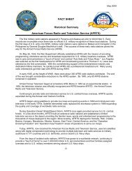
The American Forces Radio and Television Service (<strong>AFRTS</strong>) is an activity of the<br />
Internal Communications (IC) under the direction of the Assistant Secretary of<br />
<strong>Defense</strong> for Public Affairs (ASD/PA). The <strong>AFRTS</strong> mission is to provide radio and<br />
television information and entertainment programming to Department of <strong>Defense</strong><br />
(DoD) personnel and their family members stationed overseas or serving at sea<br />
where English language broadcast service is unavailable or inadequate. The<br />
programs are representative of those seen and heard in the United States, and<br />
are provided without censorship, propagandizing or manipulation.<br />
<strong>AFRTS</strong> is strictly non-commercial and is thus obligated to remove commercial<br />
announcements appearing in its programming sources. These commercials are<br />
replaced with spot announcements that communicate Department of <strong>Defense</strong><br />
(DoD) internal information themes and public service messages of interest to<br />
DoD personnel and their family members. Since dissemination of internal and<br />
command information is the primary <strong>AFRTS</strong> mission, information and<br />
entertainment programs provided by <strong>AFRTS</strong> serve as excellent vehicles for this<br />
purpose.<br />
<strong>AFRTS</strong> acquires the right to use television programming from many sources at<br />
extremely low cost. Most often, the cost to the government is no more than the<br />
program owner’s administrative cost. Once acquired, we distribute the programs<br />
from the <strong>AFRTS</strong> <strong>Defense</strong> <strong>Media</strong> <strong>Center</strong> (formerly the Broadcast <strong>Center</strong>), with<br />
assurances to the program owners that we will take all reasonable actions to limit<br />
our distribution to Department of <strong>Defense</strong> personnel.<br />
The <strong>AFRTS</strong> authorized audience is Department of <strong>Defense</strong> personnel and their<br />
families living and working overseas and privilege-holding employees of<br />
companies working DoD contracts. Since 1942, <strong>AFRTS</strong> has provided news,<br />
sports, information, and entertainment to this audience. Today, we operate in<br />
nearly every country around the world, have over 1,000 outlets around the world<br />
and are on Navy ships at sea, serving close to a million U.S. military personnel<br />
and their families. We must do everything in our power to ensure the continued<br />
availability of these programs for our service men and women. The loss of this<br />
programming would have a serious, negative effect on the quality of life for the<br />
soldiers, sailors, airmen, and Marines serving around the world who have<br />
become accustomed to this “touch of home.” That is why we go to such great<br />
lengths to protect the copyrights of programs. The <strong>AFRTS</strong> audience also bears<br />
this responsibility and must protect programming from misuse.<br />
1-1
<strong>Defense</strong> <strong>Media</strong> <strong>Center</strong> <strong>Satellite</strong> <strong>Handbook</strong> V.3.26<br />
How do I request <strong>AFRTS</strong> ® service?<br />
<strong>AFRTS</strong> equipment can be obtained two ways, by direct purchase or temporary loan. Both<br />
options require submission of a completed “Request for Service” form to <strong>AFRTS</strong>.<br />
Access to <strong>AFRTS</strong> programming is restricted by DoD regulations.<br />
You are eligible to receive <strong>AFRTS</strong> programming if you meet the following criteria.<br />
� Active Duty US military stationed or deployed overseas and their accompanying family<br />
members.<br />
� DoD civilians assigned or deployed overseas and their accompanying family members.<br />
� Direct Hire US Government State Department employees assigned overseas.<br />
� DoD Direct Hire Contractors who are US citizens and directly sponsored by the host<br />
command.<br />
� Retired US military members may purchase decoders from military exchanges or directly<br />
from <strong>AFRTS</strong>.<br />
DoD Contractors must meet additional eligibility requirements<br />
� Command supported DoD contractors overseas must have an official identification card<br />
issued by the DoD, Combatant Command or Major Command.<br />
� This ID must be presented at any military exchange in order to purchase a decoder.<br />
� If purchasing a decoder through the mail, the supported command must fax or scan and<br />
email a copy of the ID to DSN 312-328-0624 (fax) or decoders@dma.mil.<br />
� Military commands may purchase decoders for use by authorized contractors, but the<br />
decoders must be registered to the command, not individual contractors.<br />
Obtaining Loaned <strong>AFRTS</strong> equipment<br />
Loaned <strong>AFRTS</strong> equipment must be set up in an area where the majority of the troops assigned<br />
will have access to the programming. Systems set up in morale tents, mess tents or similar areas<br />
meet this requirement. <strong>AFRTS</strong> satellite signal decoders, satellite dishes, low noise block<br />
converter (LNB’s), line amplifiers and other equipment, excluding cable, that is released to a unit<br />
on a temporary loan must be returned to <strong>AFRTS</strong> upon completion of the deployment. The unit<br />
that receives <strong>AFRTS</strong> equipment is fiscally responsible for the gear until it is returned to <strong>AFRTS</strong>.<br />
<strong>AFRTS</strong> signal decoders are individually addressable and controllable, just like the commercial<br />
satellite providers Direct TV or Dish Network in the United States. This means that <strong>AFRTS</strong> can<br />
“turn off” decoders that are missing, stolen or still activated after the date the receiving unit listed<br />
as their rotation date from the deployed location. It is critical each unit maintain frequent contact<br />
with the Air Force Broadcasting Service and update changes in location, rotation date or<br />
personnel responsible for <strong>AFRTS</strong> equipment in order to prevent decoder deactivation.<br />
Direct purchase of <strong>AFRTS</strong> equipment<br />
Units that deploy often are highly encouraged to use unit funds to purchase the equipment<br />
needed to obtain the <strong>AFRTS</strong> signal. Purchasing the equipment will allow your unit near instant<br />
access to <strong>AFRTS</strong> programming at any deployed location practically anywhere on the planet<br />
outside the United States. Since you control the equipment, you won’t have to wait for it to be<br />
shipped to you or run the risk of it getting lost in the supply system.<br />
1-2
<strong>Defense</strong> <strong>Media</strong> <strong>Center</strong> <strong>Satellite</strong> <strong>Handbook</strong> V.3.26<br />
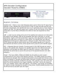
Units can procure the Scientific Atlanta Model D9865 <strong>AFRTS</strong> integrated receiver/decoder (IRD)<br />
through the Television-Audio Support Activity (T-ASA) site<br />
http://tasa.dodmedia.osd.mil/log/index.htm. A help file is available on the "requisition on-line<br />
processing" page. Several distributors offer dishes that will work with our satellite network or you<br />
can purchase from T-ASA.<br />
What do I do once I have the decoder?<br />
Once the decoder or decoders have arrived, please refer to the setup directions<br />
for your area of the world in Chapter 4 of this booklet. Once the satellite dish has<br />
been installed and the decoder is receiving a locked+sig indication the decoder<br />
can then be authorized for <strong>AFRTS</strong> programming reception.<br />
To request a decoder authorization customers should log on to the PowerVu<br />
Connect site at https://pvconnect.net. Select “authorize decoders. Customers<br />
should then complete the decoder authorization request form by filling in the<br />
decoders TID and UA number (Tracking ID and User Address) and other<br />
requested information. The decoder request information will be reviewed by<br />
<strong>AFRTS</strong>-HQ. Leased customer request authorizations must originate from the<br />
military exchange or store that leases the decoder. Individual requests for leased<br />
decoder authorization will be rejected. Approved authorizations should occur<br />
within 24 hours upon receipt of the request.<br />
If the Internet and e-mail access are not available to the requestor (remote<br />
locations), customers who purchased a decoder can contact the <strong>Defense</strong> <strong>Media</strong><br />
<strong>Center</strong> directly at commercial (951) 413-2339, or DSN (312) 348-1339, or<br />
<strong>AFRTS</strong>-HQ at commercial (703) 428-0616, or DSN (312) 328-0616. IRD's will be<br />
entered manually into the https://pvconnect.net web site by “on-call”<br />
technologists receiving this information. Callers will need to have the Tracking<br />
Identification (TID) number and model number of each decoder available to<br />
provide to the technologist in order to activate the decoders. See appendix E for<br />
details on the web procedure.<br />
What can the organization do if there are not enough DoD<br />
people to justify a free <strong>AFRTS</strong> ® decoder or the free decoder will<br />
not serve everyone?<br />
As a general rule, only one decoder or set of decoders (if cabled) is provided per<br />
location. If additional decoders are desired, they may be purchased by the<br />
organization (military unit or embassy), with HQ <strong>AFRTS</strong> approval, at an<br />
approximate cost of $276.00 each at military exchanges or $399 directly from<br />
Scientific Atlanta, depending on the type of decoder, plus shipping. Ancillary<br />
equipment such as the satellite dish, LNB, feedhorn and connecting cable can<br />
also be purchased via the <strong>Defense</strong> <strong>Media</strong> <strong>Center</strong> (DMC). The telephone number<br />
at DMC is (951) 413-2429.<br />
Contact HQ <strong>AFRTS</strong> Operations at DSN (312) 328-0616 or commercial (703)<br />
428-0290/0616 or by email: decoders@hq.afis.osd.mil to request an organization<br />
purchase of decoders. Once approved, <strong>AFRTS</strong> will provide a letter to DMC<br />
authorizing the sale.<br />
1-3
<strong>Defense</strong> <strong>Media</strong> <strong>Center</strong> <strong>Satellite</strong> <strong>Handbook</strong> V.3.26<br />
Can I lease or rent a decoder instead of buying one?<br />
AFES and NEXCOM lease the Scientific Atlanta PowerVu decoders for<br />
approximately $25 a month in both the European and Japan/Korea theaters. The<br />
cost to buy the decoder and dish is several hundred dollars and this option is<br />
only available in Europe. Check with your local European exchange for current<br />
system pricing. The dish requires installation and a length of coaxial cable to<br />
connect the dish to the satellite receiver.<br />
Can I buy my own decoder?<br />
<strong>AFRTS</strong> cannot sell decoders to private individuals. Although HQ <strong>AFRTS</strong><br />
approves the sale of decoders to commands AAFES or NEXCOM now sells and<br />
leases the equipment to authorize individuals. Decoders bought though Internet<br />
web sites such as “Ebay.com” will not work on our system and will not be<br />
authorized to receive programming.<br />
For updates on the leasing process contact HQ <strong>AFRTS</strong> Operations at DSN<br />
(312) 328-0616 or commercial 703-428-0616, FAX commercial (001) (703) 428-<br />
0624, or DSN (312) 328-0624, or email: afrtops1@hq.afis.osd.mil.<br />
Reauthorization of decoders<br />
Authorizations expire three years after the date of the initial authorization<br />
request. If you are remaining overseas more than three years, you must resubmit<br />
the authorization request to https://pvconnect.net/. To avoid a break in service,<br />
submit your reauthorization request at least a month before your current<br />
authorization expires.<br />
If your authorization expires you will be automatically switched to a channel<br />
telling you to update your registration. Then you must log on to<br />
www.pvconnect.net and update your authorization information. Leased decoder<br />
authorization updates must originate from the military exchange or store that<br />
leases the decoder. Individual requests for leased decoder authorization updates<br />
will be rejected. Approved authorizations should occur within 24 hours upon<br />
receipt of the request.<br />
Resale of decoder<br />
You may only sell a decoder to another authorized audience member. Members<br />
of the authorized audience include:<br />
o U.S. active duty military service members and their family members.<br />
o U.S. Department of <strong>Defense</strong> (DoD) or Non-Appropriated Fund (NAF)<br />
civilians and their family members.<br />
o U.S. military retirees and their family members.<br />
In cases of resale, the new owner must immediately log onto www.pvconnect.net<br />
and re-register the decoder. The seller must inform us by email at<br />
decoders@hq.afis.osd.mil that the decoder has been sold to another person.<br />
1-4
<strong>Defense</strong> <strong>Media</strong> <strong>Center</strong> <strong>Satellite</strong> <strong>Handbook</strong> V.3.26<br />
Chapter 2 : Activation Procedures and Database Management.<br />
Why do I need authorization?<br />
The American Forces Radio and TV Service (<strong>AFRTS</strong>) must ensure that only<br />
authorized audience members own or lease an <strong>AFRTS</strong> PowerVu decoder.<br />
According to Department of <strong>Defense</strong> regulations, only the following individuals<br />
are eligible to receive <strong>AFRTS</strong>: Active duty US military service members and DoD<br />
civilians assigned or deployed overseas, and their accompanying family<br />
members; Direct Hire US Government State Department Employees assigned<br />
overseas, DoD Direct Hire Contractors who are US citizens and specifically<br />
authorized by the host command. Additionally, retired military may purchase<br />
decoders at exchanges selling them or directly from Scientific Atlanta with<br />
permission from HQ <strong>AFRTS</strong>. The American Forces Radio and Television<br />
Service (<strong>AFRTS</strong>) acquire the rights for the programming you see via an <strong>AFRTS</strong><br />
PowerVu decoder. Program owners give <strong>AFRTS</strong> the rights to their programming<br />
at little or no cost, as a public service to U.S. military members stationed<br />
overseas. This programming is worth a great deal of money and commercial<br />
networks commonly pay millions of dollars for individual episodes of popular<br />
programs. To ensure that it continues to receive programming at little or no cost,<br />
<strong>AFRTS</strong> must promise that only the authorized audience will be able to view its<br />
services. Your Power-Vu decoder is one part of an elaborate security system that<br />
protects <strong>AFRTS</strong> Programming from unauthorized audiences. <strong>AFRTS</strong> must<br />
authorize (or turn on) each decoder individually, over its satellite links, from the<br />
<strong>AFRTS</strong> Headquarters in Alexandria, VA or the <strong>Defense</strong> <strong>Media</strong> <strong>Center</strong> at March<br />
Air Reserve Base, California.<br />
How do I get the decoder authorized?<br />
When you have received the decoder, refer to the setup procedures for your area<br />
of the world at http://www.afrts.osd.mil/tech_info/page.asp?pg=tech_info and in<br />
Chapter 4 of this document. To request a decoder authorization customers must<br />
log on to the PowerVu Connect site at www.pvconnect.net and select “authorize<br />
decoders.” Customers then complete the decoder authorization request form by<br />
filling in the decoders Tracking Identification number (TID) and Unit Address (UA)<br />
and other requested information. The decoder request information will be<br />
reviewed by <strong>AFRTS</strong>-HQ. Leased decoder customer request authorizations must<br />
originate from the military exchange or store that leases the decoder. Individual<br />
requests for leased decoder authorization will be rejected. Approved<br />
authorizations should occur within 24 hours upon receipt of the request. If the<br />
Internet and e-mail access are not available to the requestor (remote locations),<br />
customers who purchased a decoder can contact the <strong>Defense</strong> <strong>Media</strong> <strong>Center</strong><br />
Help Desk directly at commercial (951) 413-2339, DSN (312) 348-1339 Or<br />
<strong>AFRTS</strong>-HQ at commerical (703) 428-0616, DSN (312) 328-0616. Callers will<br />
need to have the decoder TID and UA numbers and model number of each<br />
decoder available to provide to the technologist in order to activate the decoders.<br />
2-5
<strong>Defense</strong> <strong>Media</strong> <strong>Center</strong> <strong>Satellite</strong> <strong>Handbook</strong> V.3.26<br />
How long does it take to get the decoder turned on?<br />
It is the goal of HQ <strong>AFRTS</strong> to activate your decoder within 24 hours after<br />
receiving your request. Once the owner and location of the decoder has been<br />
verified in the <strong>AFRTS</strong> database, the decoder will be activated. The decoder will<br />
stay activated unless it is physically turned off by HQ <strong>AFRTS</strong> Operations.<br />
How do you keep track of all these decoders?<br />
All authorized viewers possessing an <strong>AFRTS</strong> PowerVu decoder are entered into<br />
the <strong>AFRTS</strong> PowerVu Connect decoder database when they request decoder<br />
authorization at www.pvconnect.net. This database is highly secure with access<br />
restricted to HQ <strong>AFRTS</strong> program managers, <strong>Defense</strong> <strong>Media</strong> <strong>Center</strong><br />
Engineers/Technologists and AAFES/NAVY Exchange Trusted Agents at stores<br />
that lease decoders. The required information includes: The decoder owner’s<br />
name, status (DoD, State Department, military retiree, etc), mailing address,<br />
work phone, country, city and DEROS Date (3 years or less) and other remarks<br />
that help us identify who we are serving. It is maintained by the program<br />
managers at HQ <strong>AFRTS</strong> Operations.<br />
What do I do if or when my authorization period is up?<br />
You can avoid this by keeping your DEROS and address information current. If<br />
your authorization does expire, you will be automatically switched to a channel<br />
telling you to update your DEROS or registration information. Then you must log<br />
on to www.pvconnect.net and update your DEROS information to have the<br />
decoder authorized again. <strong>AFRTS</strong> will only authorize decoders for a maximum of<br />
three years at a time.<br />
What are the direct exchange (DX) procedures for <strong>AFRTS</strong> ®<br />
PowerVu equipment?<br />
Depending whether the decoder is government owned, customer owned,<br />
customer leased, or US Navy owned one of four different procedures are<br />
followed. These procedures are found in this chapter.<br />
Government issued decoders: The direct exchange (DX) procedure is based<br />
upon the former Television-Audio Support Activity (now <strong>Defense</strong> <strong>Media</strong> <strong>Center</strong>)<br />
External Policy and Procedure, dated August 29, 1996 and provides DX<br />
procedures for all models of <strong>AFRTS</strong> provided Power Vu Integrated Receiver-<br />
Decoders (IRD). Customer purchased equipment is discussed later in this<br />
chapter.<br />
All activities will operate in accordance with these procedures. Local repair of<br />
PowerVu equipment is NOT authorized.<br />
When it is determined that a piece of Power Vu Equipment is defective, furnish<br />
the following information:<br />
� Model number(s) of the defective unit(s). Rack mountable commercial<br />
9223 IRDs are provided in three Models: 803-200, 803-201 and 803-202.<br />
2-6
<strong>Defense</strong> <strong>Media</strong> <strong>Center</strong> <strong>Satellite</strong> <strong>Handbook</strong> V.3.26<br />
These model designations are provided as part of a bar code on the front<br />
of the units. The set top unit that uses a remote control is Model 9234 or<br />
9834.<br />
� Tracking identification number(s) (TID). The 9223 units are marked with<br />
the TID as a part of the front panel bar code. The TID for 9234 IRDs is on<br />
the bottom of the equipment or on the rear. The TID for the 9834 is<br />
located on the back.<br />
� Quantity, by model, of defective units. Please provide us the number of<br />
defective decoders by model number. Example: (2) 202s, (3) 201s, (13)<br />
and 9234s.<br />
� Symptoms of defect(s). Provide as much information as possible to assist<br />
with the troubleshooting and repair of the equipment.<br />
� Point of contact (POC) should include: name, telephone number<br />
(DSN/commercial), Fax number (DSN/commercial) and, if possible, the E-<br />
Mail address.<br />
� Return shipping address.<br />
Notifications of defective equipment are preferred via E-Mail, however, fax, letter,<br />
or messages are acceptable alternatives.<br />
E-Mail Addresses:<br />
To: powervu@dodmedia.osd.mil<br />
cc: afrtops@hq.afis.osd.mil<br />
afrtops2@hq.afis.osd.mil<br />
afrteng@hq.afis.osd.mil<br />
dee@dodmedia.osd.mil<br />
Mailing addresses:<br />
To: Television-Audio Support Activity<br />
Attn: Video Compression (DX Program)<br />
23755 Z Street<br />
Riverside, Ca. 92518<br />
cc: <strong>AFRTS</strong> HQ/Engineering<br />
601 N. Fairfax Street, Room 360<br />
Alexandria, VA 22314<br />
2-7
<strong>Defense</strong> <strong>Media</strong> <strong>Center</strong> <strong>Satellite</strong> <strong>Handbook</strong> V.3.26<br />
American Forces Radio and Television Service<br />
<strong>Defense</strong> <strong>Media</strong> <strong>Center</strong><br />
23755 Z Street<br />
Riverside, CA 92518<br />
Message addresses:<br />
To:<br />
Info: AMFINFOS WASHINGTON DC//<strong>AFRTS</strong>//<br />
CDR <strong>AFRTS</strong> BC MARCH FLD CA//DOEE//<br />
Fax numbers:<br />
<strong>AFRTS</strong>: DSN (312) 328-0624<br />
<strong>AFRTS</strong>: Commercial (703) 428-0624<br />
<strong>AFRTS</strong>-BC: DSN (312) 348-1457<br />
<strong>AFRTS</strong>-BC Commercial: (951) 413-2457<br />
Upon receipt of a notification of defective equipment, Scientific Atlanta (SA) will<br />
be contacted and requested to provide a Return Materiel Authorization (RMA)<br />
number and the address to ship the defective unit. The <strong>Defense</strong> <strong>Media</strong> <strong>Center</strong><br />
(DMC) will then advise all parties of the RMA and the shipping address. Do not<br />
ship until you are given disposition instructions by DMC. Additionally, the DMC<br />
will de-authorize the defective unit(s) in the decoder database.<br />
Ensure that the equipment is packed properly, marked and shipped by traceable<br />
means. The remote control must be included with the shipment of a desktop<br />
decoder. Notify DMC with complete shipping information of the defective<br />
equipment being returned for repair. DMC will ship a replacement, if available,<br />
and provide the TCN, method, mode, and date of shipment.<br />
Ensure that the equipment is packed properly, marked and shipped by traceable<br />
means. The remote control must be included with the shipment of a desktop<br />
decoder.<br />
Exchange/repair Points of Contact:<br />
<strong>Defense</strong> <strong>Media</strong> <strong>Center</strong> (formerly T-ASA) Logistics<br />
Commercial (951) 413-2429<br />
DSN (312) 348-1429<br />
Fax commercial (951) 413-2463<br />
DSN Fax (312) 348-1463<br />
E-Mail: PowerVu@dodmedia.osd.mil<br />
<strong>Defense</strong> <strong>Media</strong> <strong>Center</strong> Technical Points of Contact:<br />
Technologist (24-hours a day)<br />
2-8
<strong>Defense</strong> <strong>Media</strong> <strong>Center</strong> <strong>Satellite</strong> <strong>Handbook</strong> V.3.26<br />
DSN (312) 348-1339 or commercial 951-413-2339.<br />
E-Mail: technologist@dodmedia.osd.mil<br />
They have a computer program to provide azimuth, elevation and decoder<br />
settings and can assist with troubleshooting.<br />
Duty Engineer<br />
DSN (312) 348-1236, and ask for the engineer.<br />
Commercial (951) 413-2236, then Press 1<br />
E-mail: dee@dodmedia.osd.mil<br />
<strong>Defense</strong> <strong>Media</strong> <strong>Center</strong> Engineering<br />
Commercial (951) 413-2429<br />
DSN (312) 348-1429<br />
Fax Commercial (951) 413-2463<br />
DSN FAX (312) 348-1463<br />
E-mail: powervu@dodmedia.osd.mil<br />
HQ <strong>AFRTS</strong> Operations and Policy:<br />
DSN (312) 328-0616 or commercial 703-428-0616<br />
DSN (312) 328-0290, or commercial (703) 428-0290,<br />
Fax commercial (703) 428-0624, DSN (312) 328-0624<br />
E-Mail: afrtops@hq.afis.osd.mil<br />
E-Mail: afrtops2@hq.afis.osd.mil<br />
What are the repair procedures for customer purchased<br />
PowerVu Integrated Receiver Decoder (IRD) equipment?<br />
PowerVu Decoders purchased by authorized audience members for personal<br />
use are repaired via the manufacturers warranty provided at the time of purchase<br />
from the Military Exchange or Scientific Atlanta. If the warranty has expired then<br />
repair is at the owner’s expense. HQ <strong>AFRTS</strong> and Military Exchanges maintain a<br />
list of authorized repair facilities for both Europe and Japan/Korea or the<br />
defective decoder can be returned for repair to the manufacturer, Scientific<br />
Atlanta. If using the Scientific Atlanta option ask for a return material<br />
authorization (RMA) to return the IRD for repair. The Scientific Atlanta Technical<br />
Assistance <strong>Center</strong> Customer Service Representative can be reached at (800)<br />
873-4613 or from overseas dial (770) 236-4786. You can also visit the Scientific<br />
Atlanta PowerVu technical website for a list of worldwide toll free access<br />
numbers for the country you are located.<br />
http://www.scientificatlanta.com/products/customers/service_content_distribution<br />
_numbers.htm<br />
What are the repair procedures for customer leased PowerVu<br />
Integrated Receiver Decoder (IRD) equipment?<br />
Customers who are leasing a decoder should return it to the exchange that it is<br />
being leased from. The exchange should contact Scientific Atlanta via fax, email,<br />
2-9
<strong>Defense</strong> <strong>Media</strong> <strong>Center</strong> <strong>Satellite</strong> <strong>Handbook</strong> V.3.26<br />
or phone to receive an RMA and instructions for returning the units to be<br />
repaired.<br />
What are the repair procedures for decoders from Navy Ships<br />
and Fleet Support Detachments?<br />
Navy personnel will contact the nearest FSD when they have a defective<br />
decoder. The FSD will do a one-for-one exchange taking the broken decoder and<br />
replacing it with a working one. The FSD then requests an RMA number from<br />
TASA to return the broken decoder to Scientific Atlanta for repair. The FSD will<br />
ship the decoder directly to Scientific Atlanta. Finally Scientific Atlanta will send<br />
the repaired unit back to FED EX to the Naval <strong>Media</strong> <strong>Center</strong>’s warehouse.<br />
2-10
<strong>Defense</strong> <strong>Media</strong> <strong>Center</strong> <strong>Satellite</strong> <strong>Handbook</strong> V.3.26<br />
Chapter 3 : <strong>AFRTS</strong> ® <strong>Satellite</strong> Networks<br />
American Forces Radio and Television Service (<strong>AFRTS</strong>) uses a combination of<br />
domestic and international satellites to deliver radio and television programming<br />
and data products to its audience around the world. Two satellite networks are in<br />
place: the <strong>AFRTS</strong> <strong>Satellite</strong> Network (SATNET) and the <strong>AFRTS</strong> Direct-To-Sailor<br />
<strong>Satellite</strong> Network (DTS). SATNET is made up of a C-Band satellite service to the<br />
Atlantic Ocean Region (AOR) and the Western Pacific Ocean Region (POR), and<br />
Ku-Band direct-to-home satellite services, which are available in the greater<br />
European and Southwest Asia theatres, and Japan and Korea and The<br />
Philippines. DTS satellite services are broadcast on C-band and are available in<br />
three service areas: the Pacific Ocean Area (POR), the Atlantic Ocean Area<br />
(AOR), and the Indian Ocean Region (IOR). The network operating system for<br />
the SatNet network is an MPEG-2 video compression system broadcasting<br />
multiple channels of television, radio and data services. The DTS network uses a<br />
similar system using MPEG-1 video compression. The program material for the<br />
domestic and international legs of the SATNET C-band Service and the DTS<br />
networks originate from the <strong>AFRTS</strong> <strong>Defense</strong> <strong>Media</strong> <strong>Center</strong> (DMC) located at<br />
March Air Reserve Base east of Los Angeles, California. Programming for the<br />
European leg of the network, known as SATNET Ku-band Service, originates<br />
from the <strong>AFRTS</strong>-BC with regional programming added by AFN Europe located in<br />
Frankfurt, Germany and Vicenza, Italy. Programming for the Pacific Ku band<br />
service also originates from <strong>AFRTS</strong>-BC with regional programming by AFN|prime<br />
Pacific located in Tokyo Japan.<br />
Introduction to PowerVu<br />
<strong>AFRTS</strong> uses a digital video compression system that allows for the delivery of<br />
multiple channels of programming simultaneously over each of the satellite<br />
networks described above. The Scientific Atlanta PowerVu system is used by<br />
<strong>AFRTS</strong> and was designed to conform to the Moving Picture Experts Group<br />
(MPEG) and European Digital Video Broadcasting (DVB) standards for digital<br />
video compression. PowerVu is a full MPEG digital video compression system<br />
which not only provides <strong>AFRTS</strong> with a flexible operating system for multiple<br />
channel transmission; it also provides state-of-the-art network and subscriber<br />
management capabilities combined together into one satellite transmission<br />
stream. PowerVu also provides for encryption, which ensures that only<br />
authorized users have access to <strong>AFRTS</strong> programming. One of the most powerful<br />
capabilities of PowerVu is the Virtual Channel feature, which allows <strong>AFRTS</strong>-BC<br />
to create various programming channel combinations to suit audience needs.<br />
Other features include the use of error correction, which helps to overcome noisy<br />
satellite transmissions.<br />
Historically, television broadcasting has placed a great demand on satellites,<br />
particularly in terms of bandwidth and transmit power. The television signal<br />
contains an extraordinary amount of electronic information, all of which needs to<br />
be received by the viewer’s television set in order to recreate acceptable pictures<br />
and sound. There is a direct relationship between the amount of electronic<br />
3-1
<strong>Defense</strong> <strong>Media</strong> <strong>Center</strong> <strong>Satellite</strong> <strong>Handbook</strong> V.3.26<br />
information transmitted (more is better) and the bandwidth and power used for<br />
that transmission. Simply put, the information transmit rate is directly proportional<br />
to the bandwidth required and, assuming all other factors being equal, the<br />
bandwidth is directly proportional to the amount of power required. The size of<br />
the required receive antenna is inversely proportional to the effective isotropic<br />
radiated power (EIRP) from the satellite. The <strong>AFRTS</strong> system takes advantage of<br />
the relationship between bandwidth and power in a couple of ways.<br />
First, the system uses video compression technology to squeeze multiple<br />
television channels into the same transmitted channel bandwidth as was used by<br />
the previous <strong>AFRTS</strong> transmission scheme for a single channel. Secondly, by<br />
reducing the information rate but not reducing the power means, particularly in<br />
the case of DTS, that there is more power available for each bit of transmitted<br />
information. In more technical terms there is a higher ratio of energy per data bit<br />
in the transmit data stream and this translates ultimately into a reduction in the<br />
size of the receive antenna required to produce acceptable pictures and sound.<br />
Figure 3-1 Block level system diagram<br />
Figure 3-1 shows a simplified block diagram of the PowerVu system of MPEG-2<br />
encoders, multiplexer, transmission, and decoding equipment. Analog video and<br />
audio signals are presented to PowerVu encoders where they are converted into<br />
digital signals and then compressed into an MPEG format. The compression<br />
process removes digital bits that are either not needed by the PowerVu system,<br />
or are redundant picture and sound information that PowerVu temporarily<br />
removes during satellite transmission and then reinserts during the process of<br />
restoring the original signals in the compression decoder. In the <strong>AFRTS</strong> system<br />
as many as eight encoders feed a single PowerVu multiplexer which performs<br />
several functions including combining of multiple encoder signals, addition of<br />
utility data to the combined data stream, signal encryption or scrambling, and<br />
processing of program guide information. The multiplexer’s output signal is then<br />
modulated and amplified for transmission over a satellite link. At a satellite<br />
3-2
<strong>Defense</strong> <strong>Media</strong> <strong>Center</strong> <strong>Satellite</strong> <strong>Handbook</strong> V.3.26<br />
downlink, a PowerVu Integrated Receiver Decoder (IRD) performs all of the<br />
necessary functions to receive, demodulate, and decode the video, audio, and<br />
data signals from the single MPEG data stream.<br />
<strong>AFRTS</strong> employs encryption and scrambling in its PowerVu operating system to<br />
ensure that only authorized viewers are able to receive programming. The<br />
PowerVu system not only allows <strong>AFRTS</strong> to individually control both the general<br />
overall authorization of compression decoders, that is controlling whether or not a<br />
decoder can receive and decode the MPEG signal, but it also provides for the<br />
control of individual services available to the decoder. For example, <strong>AFRTS</strong> can<br />
blackout an individual channel or program authorization to a single decoder if the<br />
need ever arises.<br />
Once the picture and sound information are converted into MPEG digital bit<br />
streams by the PowerVu encoders, it is possible to mix and match video data<br />
from one source with audio data from another to create a totally unique channel.<br />
This is the basic concept of PowerVu virtual channels and it is a capability that<br />
<strong>AFRTS</strong> has taken advantage of in the design of the various satellite networks.<br />
The operational and technical needs of a cable television head end operator may<br />
differ significantly, for example, from that of an <strong>AFRTS</strong> affiliate broadcast station.<br />
As was mentioned earlier, the PowerVu compression decoders can be outfitted<br />
with a wide range of options such as up to four channels of stereo radio<br />
programming. The PowerVu system allows <strong>AFRTS</strong> the ability to match, for<br />
example, entertainment television programming which has been timed for a<br />
particular geographic region with similarly programmed radio services. PowerVu<br />
also allows for the manipulation of the utility and high-speed data programming<br />
by means of the virtual channel feature.<br />
The MPEG standard was designed with a degree of extensibility, which is the<br />
ability to add services to the transmission signal other than television and radio<br />
programming. One of these services that PowerVu provides and <strong>AFRTS</strong> is taking<br />
advantage of is utility data service. The utility data feature of PowerVu has been<br />
designed to be very simple and can be thought of as a data pipe. A PC or other<br />
data source simply transmits the serial data into the multiplexer by way of a<br />
communications program, and it is available without modification at the decoder<br />
as though it had been transmitted through a computer network cable.<br />
3-3
<strong>Defense</strong> <strong>Media</strong> <strong>Center</strong> <strong>Satellite</strong> <strong>Handbook</strong> V.3.26<br />
Figure 3-2 Connecting an IRD to a monitor or TV receiver<br />
The integrated receiver/decoder (IRD) is a primary link to <strong>AFRTS</strong> satellite<br />
broadcasts. Without a properly authorized and configured IRD it is not possible to<br />
use or access any of the television or radio programming or data services<br />
provided by <strong>AFRTS</strong>. The compression decoder is designed to receive and<br />
decode the satellite signal and then to demodulate, decompress, and decrypt the<br />
available and authorized programming services. Figure 3-2 shows typical block<br />
diagrams of the connection between a satellite antenna, a PowerVu IRD, and the<br />
users own equipment. All PowerVu IRDs are designed to be connected to a<br />
satellite Frequency (RF) signal that is in the L-band frequency range between<br />
950 and 1450 MHz. However, the satellite technology in use today does not<br />
allow for transmissions back to earth in that frequency range. Users wishing to<br />
receive any of the <strong>AFRTS</strong> satellite signals directly must outfit their antennas with<br />
a Low Noise Block Converter Amplifier, or LNB. The signal from the LNB output<br />
is connected directly to, in most cases, the input of the IRD and, as Figure 3-2<br />
shows, the video and audio outputs from the IRD are connected directly to the<br />
users equipment. The user then simply changes the IRD to a virtual channel, and<br />
provided the IRD is authorized by <strong>AFRTS</strong>, receives the television and radio<br />
services of that virtual channel much like any cable or direct-to-home television<br />
service in the world.<br />
3-4
<strong>Defense</strong> <strong>Media</strong> <strong>Center</strong> <strong>Satellite</strong> <strong>Handbook</strong> V.3.26<br />
SATNET C-Band <strong>Satellite</strong> and Japan/Korea Ku-band Services<br />
<strong>AFRTS</strong>-BC compiles the video and audio programming from the major US<br />
television and radio networks such as ABC, CBS, NBC, FOX and ESPN. Data<br />
Figure 3-3 <strong>AFRTS</strong> SATNET network diagram<br />
programming is supplied to <strong>AFRTS</strong>-BC from a variety of DoD and commercial<br />
sources. All of this programming is then electronically manipulated into the<br />
unique<br />
SATNET<br />
television,<br />
radio, and<br />
data channels<br />
that are then<br />
transmitted<br />
around the<br />
world. Figure<br />
3-3 shows the<br />
overall<br />
SATNET<br />
architecture.<br />
Figure 3-4 <strong>AFRTS</strong> SATNET IntelSat Galaxy 28 footprint<br />
3-5<br />
The domestic<br />
and<br />
international<br />
SATNET C-band feeds originate at <strong>AFRTS</strong>-BC where the signal is up linked to<br />
IntelSat Galaxy 28 located at 89� west. The satellite feed from IntelSat Galaxy 28
<strong>Defense</strong> <strong>Media</strong> <strong>Center</strong> <strong>Satellite</strong> <strong>Handbook</strong> V.3.26<br />
Figure 3-5 <strong>AFRTS</strong> SATNET NewSkies NSS-5 and NSS-6<br />
footprints<br />
3-6<br />
is received by <strong>AFRTS</strong><br />
customers located within<br />
the domestic satellite<br />
footprint. Refer to Figure<br />
3-4 for the satellite signal<br />
coverage from IntelSat<br />
Galaxy 28.<br />
Also receiving the<br />
domestic satellite feed<br />
are two international<br />
satellite gateways: the<br />
west gateway located at<br />
Brewster, Washington;<br />
and the east gateway<br />
located at Holmdel, New<br />
Jersey. The gateway at<br />
Brewster transmits the<br />
SATNET C-band service<br />
to the satellite located at<br />
183� east for western<br />
Pacific audiences with<br />
larger satellite dishes.<br />
This signal is received by<br />
a site in Hong Kong<br />
where it is then sent to<br />
the satellite located at<br />
95� to provide Ku-band service for audiences as far south as The Philippines and<br />
as far north as Japan. See figure 3-5 for these two signals.<br />
Similarly, the gateway in Holmdel transmits the same SATNET C-band service to<br />
the international satellite<br />
located at 1� West (359�<br />
East); its footprint can be<br />
found on figure 3-6. Pacific<br />
Ocean areas not served by<br />
the Direct-to-Home service in<br />
Japan and Korea receive DTS<br />
signals from an international<br />
satellite at 180 degrees East<br />
or C-band signals from the<br />
satellite located at 177 W.<br />
SATNET Channel Guide<br />
Appendix A provides the<br />
virtual channel information for<br />
Figure 3-6 <strong>AFRTS</strong> INTELSAT 10-02
<strong>Defense</strong> <strong>Media</strong> <strong>Center</strong> <strong>Satellite</strong> <strong>Handbook</strong> V.3.26<br />
the SATNET C-band Service. Appendix D provides additional satellite<br />
parameters.<br />
The AFN|news channels provides 24 hour a day timely news, news features,<br />
business and military news as gathered from the major networks.<br />
The AFN|sports channel features sporting events, sporting news, and feature<br />
sports programming.<br />
The AFN|prime television channels are similar to mainstream commercial<br />
television in terms of look, but surpass it in terms of content, featuring the best of<br />
American television. Each entertainment channel is programmed and scheduled<br />
to best serve a geographic audience; AFN|prime Atlantic is programmed for the<br />
European audience; AFN|prime Pacific for the Asian and Western Pacific<br />
audiences; and AFN|freedom for the Mid-East audiences.<br />
The AFN|spectrum channel is made up of programming which features movies,<br />
the best of Public Broadcasting Service, Arts & Entertainment (A&E), Discovery<br />
Channel, History Channel, and classic series and cartoons. This service is<br />
packaged into eight-hour segments that are shown three times, each eight-hour<br />
segment presenting an alternative family oriented program for each major time<br />
zone during prime time.<br />
AFN|xtra channel is a “lifestyle” channel made up of fast-paced action,<br />
excitement, and fun programming during the weekdays and a second sports<br />
channel over the weekends. During the week, it becomes home to a variety of<br />
alternative and classic sports, sports-talk, consumer high-tech, video gaming,<br />
and leading edge entertainment programming. On weekends AFN|xtra will carry<br />
live and delayed sports. Occasionally regular weekday programming will be preempted<br />
for must-see bonus live sports coverage when there’s simultaneous<br />
coverage of a high-profile event already on another AFN channel.<br />
The Pentagon channel is produced by the <strong>AFRTS</strong> News<strong>Center</strong> in Washington<br />
DC and provides extended coverage of many events that the major news<br />
networks may not necessarily cover in their entirety. The Pentagon Channel’s<br />
current daily schedule includes live events such as Pentagon Press and<br />
Operational Briefings, Secretary of <strong>Defense</strong> town hall meetings, Central<br />
Command Press and Operational Briefings, State Department and White House<br />
briefings, Capitol Hill testimony by <strong>Defense</strong> officials and other relevant events<br />
available from the National Network Pool.<br />
Multiple types of radio programming are available on the Ku-Band SATNET: The<br />
AFN Uninterruptible Voiceline radio service includes news, commentary, and<br />
special feature radio programming from a variety of U.S. commercial radio<br />
networks including AP, Fox, NPR and CNN all on a 24-hour basis. The AFN<br />
Interruptible Voiceline radio service offers the same news and commentary<br />
programming but breaks away to provide major American live sports<br />
programming at various times. Playoff and championship series will increase this<br />
number slightly. Music radio services include jazz from National Public Radio,<br />
Classic Rock, The Kidd Kraddick Morning Show on the urban channel Gravity,<br />
3-7
<strong>Defense</strong> <strong>Media</strong> <strong>Center</strong> <strong>Satellite</strong> <strong>Handbook</strong> V.3.26<br />
JackFM, Techno and Trance on the DriveFX service, and Hot AC from ABC<br />
Radio. In addition there is the mainstream country service from Dial Global.<br />
Data products are transmitted over SATNET using PowerVu utility data channel.<br />
Refer to chapter 7 of this handbook for information on data services provided by<br />
<strong>AFRTS</strong>.<br />
SATNET<br />
European Ku-<br />
Band <strong>Satellite</strong><br />
Services<br />
The American<br />
Forces Network<br />
(AFN-Europe)<br />
affiliate stations<br />
located in<br />
Frankfurt,<br />
Germany and<br />
Vicenza, Italy<br />
downlink the<br />
SATNET C-Band<br />
service and add<br />
Figure 3-7 AFNE Hotbird Coverage<br />
local European<br />
News and Information to create a unique European version of SATNET referred<br />
to as the AFN Europe Service.<br />
The AFN Europe Ku-band service originates at AFN-E where the signal is fed<br />
over a high-speed fiber optic data channel to a commercial satellite teleport<br />
located at Usingen, Germany. At Usingen, the AFN Europe Service is transmitted<br />
to Hotbird 6 located at 13� and from Vicenza Italy to and Hotbird 9 located at 9�<br />
East for broadcast to Europe and Southwest Asia. Refer to figure 3-7 for the<br />
satellite coverage area.<br />
AFN Europe Channel Guide<br />
This section provides virtual channel information for the AFN Europe Service. At<br />
the present time AFN-E programs seven American Forces Network (AFN)<br />
television services that are transmitted over the SATNET C-band Service. (See<br />
Appendix A)<br />
The AFN|news channels provides 24 hour a day timely news, news features,<br />
business and military news as gathered from the major networks.<br />
The AFN|sports channel features sporting events, sporting news, and feature<br />
sports programming.<br />
The AFN|prime entertainment television services are similar to mainstream<br />
commercial television in terms of look. Each prime entertainment service is<br />
3-8
<strong>Defense</strong> <strong>Media</strong> <strong>Center</strong> <strong>Satellite</strong> <strong>Handbook</strong> V.3.26<br />
programmed and scheduled to best serve a geographic audience: AFN|prime<br />
Atlantic is programmed to suit the European audience.<br />
The AFN|spectrum service is made up of family oriented programming which<br />
features the best of Public Broadcasting Service, Arts & Entertainment (A&E),<br />
Discovery Channel, History Channel, and classic series and cartoons. This<br />
service is packaged into eight-hour segments that are shown three times, in a<br />
24-hour period.<br />
The Pentagon channel is produced by the <strong>AFRTS</strong> News<strong>Center</strong> in Washington<br />
DC and provides extended coverage of many events that the major news<br />
networks may not necessarily cover in their entirety. The Pentagon Channel’s<br />
current daily schedule includes live events such as Pentagon Press and<br />
Operational Briefings, Secretary of <strong>Defense</strong> town hall meetings, Central<br />
Command Press and Operational Briefings, State Department and White House<br />
briefings, Capitol Hill testimony by <strong>Defense</strong> officials and other relevant events<br />
available from the National Network Pool.<br />
Multiple types of radio programming are available on the Ku-Band SATNET: The<br />
AFN Uninterruptible Voiceline radio service includes news, commentary, and<br />
special feature radio programming from a variety of U.S. commercial radio<br />
networks including AP, Fox, NPR and CNN all on a 24-hour basis. The AFN<br />
Interruptible Voiceline radio service offers the same news and commentary<br />
programming but breaks away to provide major American live sports<br />
programming at various times. Playoff and championship series will increase this<br />
number slightly. Music radio services include jazz from National Public Radio,<br />
Classic Rock, The Kidd Kraddick Morning Show on the urban channel Gravity,<br />
JackFM, Techno and Trance on the DriveFX service, and Hot AC from ABC<br />
Radio. In addition there is the mainstream country service from Dial Global, as<br />
well as the AFN Europe originated radio services.<br />
<strong>AFRTS</strong> ® Direct-To-Sailor <strong>Satellite</strong> Network (DTS)<br />
The <strong>AFRTS</strong> DTS satellite network is a digital video compression system capable<br />
of providing video, audio, and data programming to <strong>AFRTS</strong> viewers around the<br />
world including sailors and Marines at sea underway aboard US Navy ships and<br />
Pacific Ocean areas not serviced by the Direct to Home service in Japan and<br />
Korea. The transponders on the three international DTS satellites are supplying<br />
global, premium beam service at an effective isotropic radiated power (EIRP)<br />
level of 29.0 dBW (at beam edge). All three satellites transmit a left hand<br />
circularly polarized (LHCP) signal, but each has its own dedicated C-Band (3.7<br />
GHz to 4.2 GHz) downlink frequency. The network operating system uses<br />
MPEG-1 video compression technology to broadcast three video channels with<br />
their associated audio, additional stereo and monaural radio channels, and a<br />
utility data channel. All of the program material for these channels originates at<br />
the AFN <strong>Defense</strong> <strong>Media</strong> <strong>Center</strong> (DMC) located at March Air Reserve Base near<br />
Los Angeles, California.<br />
3-9
<strong>Defense</strong> <strong>Media</strong> <strong>Center</strong> <strong>Satellite</strong> <strong>Handbook</strong> V.3.26<br />
Figure 3-8 DTS <strong>Satellite</strong> network diagram<br />
DTS <strong>Satellite</strong> Network Architecture<br />
<strong>AFRTS</strong>-BC compiles the television and radio programming and data from the<br />
major US television and radio networks such as ABC, CBS, CNN, FOX, and<br />
NBC. This material is then configured into the unique DTS television, radio, and<br />
data channels that are then transmitted around the world over the <strong>AFRTS</strong> DTS<br />
satellite network. Figure 3-8 shows the overall DTS satellite network which<br />
includes a constellation of one domestic and three international satellites<br />
broadcasting the DTS signal to the three ocean regions: Atlantic Ocean Region<br />
(AOR), Indian Ocean Region (IOR), and Pacific Ocean Region (POR). The signal<br />
path to these satellites starts at AFN-BC where two independent networks are<br />
established, a DTS-POR network and a separate DTS-AOR/IOR network.<br />
3-10
<strong>Defense</strong> <strong>Media</strong> <strong>Center</strong> <strong>Satellite</strong> <strong>Handbook</strong> V.3.26<br />
The DTS-POR signal originates at AFN-BC where it is transmitted by a fiber optic<br />
high capacity data channel (45 Mbps, DS-3) to the West Coast international<br />
uplink site which relays the signal to an INTELSAT satellite located over the<br />
center of the POR service area. Refer to figure 3-9 (180° Pacific Ocean Region<br />
(POR) satellite<br />
footprint map).<br />
The DTS<br />
AOR/IOR signal<br />
also originates<br />
at AFN-BC but<br />
unlike the POR<br />
signal is up<br />
linked directly to<br />
a domestic<br />
satellite that<br />
provides the<br />
signal to the<br />
3-11<br />
East Coast<br />
international<br />
uplink site. The<br />
East Coast uplink site transmits to the NEW SKIES 7 satellite to provide the<br />
signal to the AOR<br />
service area (Figure 3-<br />
10). Located within the<br />
DTS-AOR service area<br />
is the European<br />
satellite relay facility at<br />
Madley, UK that<br />
receives the AOR<br />
signal and relays it to<br />
another INTELSAT<br />
satellite located in the<br />
IOR service area<br />
(Figure 3-11). (Note:<br />
The DTS domestic<br />
satellite link was<br />
designed for<br />
connectivity purposes<br />
Figure 3-9 IntelSat 701 Pacific Ocean<br />
Figure 3-10 New Skies NSS-7 Atlantic Ocean and Mediterranean<br />
Sea<br />
to very large antennas and is not useable to provide service for shipboard<br />
customers.)<br />
DTS Channel Guide<br />
This section provides channel information for the two DTS networks. Appendix A<br />
provides the virtual channel information for the all service networks.
<strong>Defense</strong> <strong>Media</strong> <strong>Center</strong> <strong>Satellite</strong> <strong>Handbook</strong> V.3.26<br />
At the present time <strong>AFRTS</strong> programs three television services that are<br />
transmitted over each of the two DTS <strong>Satellite</strong> Networks.<br />
The AFN|news channels provides 24 hour a day timely news, news features,<br />
business and military news as gathered from the major networks.<br />
The AFN|sports channel features sporting events, sporting news, and feature<br />
sports programming.<br />
The AFN entertainment television services are similar to mainstream commercial<br />
television in terms of look, but surpass it in terms of content, featuring the best of<br />
American television. Each entertainment service is programmed and scheduled<br />
to best serve a geographic audience. AFN|prime Pacific is transmitted over the<br />
DTS-POR system and is timed for the Japan time zone audience; AFN|prime<br />
Atlantic is transmitted over both the DTS-AOR and DTS-IOR systems and is<br />
scheduled for an audience in the Central European time zone.<br />
Two types of radio<br />
programming are available<br />
on the DTS system: AFN<br />
Voiceline and AFN stereo<br />
radio channels. AFN<br />
Voiceline radio services<br />
include news, commentary,<br />
and special feature radio<br />
programming from a variety<br />
of U.S. commercial radio<br />
networks including AP, Fox,<br />
NPR, and CNN. As the name<br />
implies, the AFN<br />
Figure 3-11IntelSat 906 Indian Ocean and Persian Gulf<br />
Uninterruptible Voiceline<br />
offers this type of<br />
programming on a 24-hour basis. The AFN Voiceline offers same news and<br />
commentary programming but breaks away to provide major American live sports<br />
programming. Playoff and championship series will increase this number slightly.<br />
The two stereo radio channels have been designed specifically for use with the<br />
DTS system. Channel one is a mix of jazz from National Public Radio, Techno<br />
and Trance service DriveFX, The Kidd Kraddick Morning Show and urban music<br />
on the Gravity channel, and Jack FM from Dial Global. Channel two is a mix of<br />
Mainstream Country, Classic Rock and Z-Rock (alternative rock) from Dial<br />
Global.<br />
Public affairs data products are transmitted over the DTS system using the 128<br />
kbps utility data channel. These include Stripes Newspaper, Early Bird, Navy<br />
News Wire Service, and the New York Times Fax. Additional data products will<br />
be added as they become available.<br />
See appendixes B and D for additional technical reference on both SATNET and<br />
DTS signals.<br />
3-12
<strong>Defense</strong> <strong>Media</strong> <strong>Center</strong> <strong>Satellite</strong> <strong>Handbook</strong> V.3.26<br />
The Pentagon Channel Network Architecture<br />
The Pentagon Channel broadcasts military information and news for the 2.6<br />
million members of the U.S. Armed Forces through programming including<br />
Department of <strong>Defense</strong> (DoD) press briefings, interviews with top <strong>Defense</strong><br />
officials, short stories about the work of our military, and military news.<br />
In addition to enhancing DoD communications with the 1.4 million active duty<br />
service members at military camps, bases, and stations in the United States and<br />
overseas, the Pentagon Channel provides the 1.2 million members of the<br />
National Guard and Reserve and the 650,000 civilian employees of the DoD<br />
more timely access to military information and news.<br />
The Pentagon Channel television service is distributed 24 hours a day, seven<br />
days a week and is available to all stateside cable and satellite providers, and via<br />
American Forces Radio and Television Service, overseas. The Pentagon<br />
Channel is also available via web cast at http://pentagonchannel.mil.<br />
The Pentagon Channel<br />
<strong>Satellite</strong> Settings<br />
The Pentagon Channel is available<br />
free of charge to all US residents and<br />
is broadcasted “in the clear” with no<br />
encryption which is unlike the SatNet<br />
and DTS services which are available<br />
only to military members and other<br />
DoD employees overseas. The<br />
Pentagon Channel is transmitted via<br />
AMC-1 at 103 degrees west longitude<br />
Figure 3-6 AMC-1 Ku coverage<br />
and can be received using an 80<br />
centimeter KU-Band satellite dish.<br />
To request the Pentagon Channel from your local cable or satellite provider, or to<br />
receive it using a digital decoder you’ll need the following coordinates and<br />
frequency information:<br />
� The satellite downlink frequency is 12.100 GHz<br />
� Vertical polarization on transponder 20<br />
� The modulation type is QPSK (quadrature phase shift keying)<br />
� The FEC (forward error correction) is 3/4<br />
� The symbol rate is 20,000 Mega-symbols per second<br />
� The MPEG Reed Solomon Coding is 204/188<br />
3-13
<strong>Defense</strong> <strong>Media</strong> <strong>Center</strong> <strong>Satellite</strong> <strong>Handbook</strong> V.3.26<br />
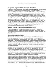
Chapter 4 : Digital <strong>Satellite</strong> Downlink Reception<br />
The <strong>AFRTS</strong> signal is a digitally compressed MPEG signal and as with any digital<br />
signal there is perfect reception or nothing at all. Tuning to an MPEG<br />
compressed digital signal, however, is a little different from tuning to a standard<br />
analog signal. Weak signals appear to be random noise; the receiver will not<br />
display any picture at all until sufficient signal is reaching the antenna. Then,<br />
once the digital threshold of the receiver/decoder is exceeded, a perfect picture<br />
will appear on the TV screen. MPEG digital reception is like a light switch; it’s on<br />
or off. This is to say that a digital signal has two states, perfect (on) picture<br />
quality and reception or nothing at all (off). Furthermore, if the installer moves<br />
past the antenna’s peak performance position, the picture will “freeze frame” on<br />
the last picture in its buffer memory. The IRD will not receive any further video<br />
until the antenna is repositioned to receive a signal above minimum receiver<br />
threshold. Peaking the signal improves the overhead above threshold and<br />
ensures a good picture under poor weather conditions.<br />
Typical <strong>Satellite</strong> TVRO Equipment Configuration<br />
The typical equipment arrangements used to receive <strong>AFRTS</strong> services are<br />
provided at Figure 3-2. Specific equipment requirements for receiving <strong>AFRTS</strong><br />
services are provided in the section titled Qualification of <strong>Satellite</strong> Terminals or<br />
Digital Reception.<br />
General <strong>Satellite</strong> Concepts<br />
The concepts underlying satellite broadcasting are straightforward: signals<br />
beamed into space by an “uplink” dish are received by an orbiting satellite,<br />
electronically processed, re-broadcast or “down-linked” back to earth and then<br />
detected by a dish and associated electronics. A receiving station can be situated<br />
anywhere within the satellite’s “footprint” (see Chapter 3, satellite footprint maps).<br />
The overwhelming strength of satellite broadcasting lies in its ability to reach an<br />
unlimited number of sites regardless of their location without the need for any<br />
physical connections.<br />
Nearly all communication satellites designated for commercial use are positioned<br />
or “parked” in the “Clarke Belt”, also known as the “geostationary” arc. The<br />
Clarke belt lies in the equatorial plane 22,300 miles above the equator. This<br />
circle around the earth is unique because in this orbit the velocity of a spacecraft<br />
matches that of the surface of the earth below. Therefore each satellite appears<br />
to remain in a fixed orbital slot in the sky above. This allows a stationary dish to<br />
be permanently aimed towards a targeted geostationary satellite.<br />
A satellite receives the up-linked signal, lowers its frequency and re-broadcasts it<br />
to any chosen geographic area. Downlink transmit antennas can target over 40%<br />
of the earth’s surface with “global” beams, can broadcast to selected countries or<br />
continents via “zone” beams, or can pinpoint smaller areas with “spot” beams.<br />
Many domestic C-band broadcast satellites direct one beam that blankets the<br />
continental U.S. and a second more localized one to the Hawaiian Islands. Ku-<br />
4-1
<strong>Defense</strong> <strong>Media</strong> <strong>Center</strong> <strong>Satellite</strong> <strong>Handbook</strong> V.3.26<br />
band satellites, operating in the higher frequency 12 GHz range, are configured<br />
for spot beams and require smaller antennas to receive their signals.<br />
The Receive Site<br />
At the receive site a dish reflects and concentrates as much of the very weak<br />
down-linked signal as possible to its focus where a feed channels the signals into<br />
the first electronic component, the low noise block converter (LNB). The signal is<br />
then cabled indoors to the satellite receiver and processed into a form that can<br />
be deciphered by a television, stereo or computer.<br />
Radio Waves and Communications<br />
The transmission of extremely low power microwaves, a form of radio waves,<br />
underlies the operation of radio, conventional television, satellite broadcasting<br />
and other man-made communication devices. They are one form of more general<br />
phenomena known as electromagnetic waves that travel at the speed of light,<br />
equal to 186,000 miles per second. At this rate, a signal travels from the uplink,<br />
to a satellite and back again to earth in about 4/10ths of a second.<br />
Radio Waves<br />
Radio waves are defined by their frequency, power and polarization. These<br />
parameters are briefly discussed below.<br />
Signal Frequency<br />
The frequency of a radio wave is the number of vibrations that occur every<br />
second. Just like the frequency of sound vibrations determines whether a musical<br />
note is either a soprano or a bass, so the frequency of radio wave determines<br />
whether they are used to transmit regular AM radio broadcasts or satellite<br />
television broadcasts. Microwaves have frequencies in excess of one billion<br />
cycles per second (known as one gigahertz and abbreviated 1 GHz) to as high<br />
as 50 GHz. C and Ku-band satellite downlink signals fall in the 4 and 12 GHz<br />
range, respectively.<br />
Polarization<br />
Radio waves can be polarized. Two standard formats commonly used in C and<br />
Ku-band satellite communication links are linear and circular polarity.<br />
Linearly polarized signals can have either vertical or horizontal polarity. In this<br />
case, the electric and magnetic fields of the signal remain in the same planes in<br />
which they were originally transmitted. Horizontally polarized waves vibrate in a<br />
horizontal plane; vertically polarized waves vibrate in a vertical plane. Most Cband<br />
signals broadcast to TVROs (television receive-only) are linearly polarized.<br />
In circularly polarized signals the electrical and magnetic fields rotate in a circular<br />
motion as they travel through space, somewhat analogous to a spiral. The<br />
direction of the rotation determines the type of circular polarization. A signal<br />
rotating in a right-hand direction is termed right-hand circular polarization (RHCP)<br />
4-2
<strong>Defense</strong> <strong>Media</strong> <strong>Center</strong> <strong>Satellite</strong> <strong>Handbook</strong> V.3.26<br />
and a signal rotating in the left-hand direction is termed left-hand circular<br />
polarization (LHCP).<br />
A principle advantage of<br />
circular polarization is the<br />
elimination of the need for<br />
skew adjustment. A feed<br />
designed to receive a linearly<br />
polarized signal must be<br />
correctly lined up with its plane<br />
of polarization to allow<br />
reception of the highest<br />
possible power and therefore<br />
clearest picture. It requires a<br />
skew adjustment for finetuning.<br />
However, a feed that<br />
receives a RHCP or LHCP<br />
Figure 4-1 <strong>Satellite</strong> dish parts<br />
signal can be attached at the<br />
focal point of the dish in any<br />
orientation.<br />
There are three noteworthy components of a satellite receive antenna which<br />
collectively capture and amplify the signal to a level large enough to break the<br />
receiver reception threshold, normally around negative 45dB. These are the<br />
reflective surface or parabolic curvature, the feedhorn and the amplifier section<br />
“Low Noise Amplifier (LNA), Low Noise Block converter (LNB), Low Noise<br />
Converter (LNC), and Low Noise Feedhorn (LNF). We will focus on these areas<br />
because they are the components that we personally come in contact with and<br />
have the greatest control over.<br />
Antenna Reflector<br />
The reflective surface in a perfect world would rely on the geometric properties of<br />
its true parabolic curve to reflect the satellite signal to a very sharp focal point.<br />
The focal point on a parabolic antenna is out in front and to the center of the<br />
surface. This would be a well-defined area if a perfect parabolic curve were<br />
defined, however this isn’t as defined as we would prefer. The focal point is not<br />
as perfect as theory would dictate but is still within a small radius and is a<br />
defining difference in a perfect or marginal signal reception. This you may say is<br />
where the “rubber meets the road” and collection of the signal is critical in this<br />
area.<br />
4-3
<strong>Defense</strong> <strong>Media</strong> <strong>Center</strong> <strong>Satellite</strong> <strong>Handbook</strong> V.3.26<br />
Reflective surfaces come in several different shapes and sizes but are most<br />
common in the parabolic or offset shape. Offset shaped antennas are nothing<br />
more than a small section of the original parabolic antenna see figure 4-2. The<br />
larger the reflective service the better defined the focal point becomes and<br />
therefore more gain can be expected. The reflector sometimes mistakenly called<br />
the antenna is the first step in a well-engineered system that will continue to<br />
provide service under harsh<br />
environments. If the size of<br />
your dish is too small for the<br />
signal you intend to capture,<br />
nothing is going to compensate<br />
for that. Working with an<br />
analog signal you could get by<br />
with a smaller dish but suffer<br />
with a noisy picture. A digital<br />
signal on the other hand is<br />
perfect or nothing situation and<br />
with a marginal or less<br />
reflective surface you can<br />
expect nothing.<br />
Many of the small aperture Kuband<br />
dishes sold these days<br />
use an offset antenna, see<br />
figure 4-2, a feedhorn design<br />
which places the focal point<br />
below the front and center of<br />
the dish. This type of antenna,<br />
Figure 4-2 An offset satellite antenna<br />
as defined earlier is actually a<br />
small oval subsection from a<br />
much larger parabolic antenna design, is oval in shape with a minor axis (left to<br />
right) that is narrower than its major axis (top to bottom). Because of its unique<br />
geometry, the offset fed antenna requires a specially designed feedhorn, which<br />
matches the antenna geometry precisely. For this reason, the offset fed antenna<br />
and feedhorn are usually sold together as a single unit. This type of feed is called<br />
a Low Noise Feed or LNF.<br />
Amplifier “LNA/B/C/F”<br />
The concentrated signal from the reflective surface is channeled to a low noise<br />
amplifier that has a very low noise floor. The job for this section is to amplify the<br />
signal to a level that is above the receiver’s threshold. The Low Noise Amplifier<br />
(LNA) amplifies the signal at the output of the earth station’s antenna. The most<br />
commonly used LNAs use gallium arsenide field effect transistors (GaAsFETs).<br />
Typical noise temperatures of amplifiers produced today range from 15° K to 60°<br />
K (LNB\C\F).<br />
4-4
<strong>Defense</strong> <strong>Media</strong> <strong>Center</strong> <strong>Satellite</strong> <strong>Handbook</strong> V.3.26<br />
The LNA is a weather sealed unit that provides enough gain to transport the<br />
signal from the antenna to the receiver. It is located as close the feedhorn as<br />
possible to minimize signal loss and thereby improving signal to noise ratio. The<br />
problem with an LNA is that the signal is in several gigahertz frequency range<br />
and requires expensive transmission lines to carry the signal from the antenna to<br />
the receiver. A much more efficient way of doing this is to down-convert the<br />
signal at the antenna to a lower frequency for transmission to the receiver. This is<br />
accomplished with the newer LNB/C/F to lower the satellite normal GHz<br />
frequencies to an L-band frequency between 940 MHz to 1450 MHz. For ease of<br />
discussion, all Low Noise Amplifier types will be referred to as a LNB, form this<br />
point forward<br />
There is a basic tradeoff between LNB noise temperature and antenna size,<br />
which is gain, expressed by the system figure of merit G/T. Smaller antennas<br />
require a cooler LNB temperature for equivalent system performance. Whereas a<br />
larger antenna allows use of an LNB with a higher noise temperature. This<br />
should not be misunderstood and you should not be mislead that an amplifier<br />
with a lower noise temperature will correct for any antenna size. G/T is a<br />
measure of the ability of a receiving system to amplify very weak signals, such as<br />
those of a satellite transmitter 22,300 miles away over the background noise. The<br />
“G” is antenna gain and the “T” is its noise temperature. The job for the LNB is to<br />
overcome this noise figure with a carrier to noise C/N separation of greater than<br />
8dB, see Spectrum Analyzer plots. The average for reliable reception of the<br />
<strong>AFRTS</strong> digital signal is 12dB of signal above the noise floor. It should be noted<br />
also that a digital signal reacts to noise and interference differently than a analog<br />
signal. Noise or interference introduced in a digital environment will cause<br />
pixelization and even loss of signal reception. Whereas in the analog world,<br />
received video will have noise or sparkles but in most instances would not suffer<br />
total loss of signal. The advantage of the digital signal is, there is no change in<br />
the signal quality until it deteriorates below the receiver reception threshold. But,<br />
at that point the received video will go from perfect to total loss of signal; notice<br />
there is no in between.<br />
The noise figure or temperature, expressed in decibels or degrees Kelvin,<br />
respectively, is a measure of the degree by which this amplifier degrades or<br />
decreases the signal-to-noise ratio of the satellite signal as it passes through the<br />
device. This scale is based on the fact that at a temperature known as absolute<br />
zero, 0° K (equal to minus 273.16° C or minus 459.72° F), molecular motion<br />
ceases and consequently all electronic noise disappears. The lower the noise<br />
temperature or figure, the better amplifier performance. There are amplifiers on<br />
the market today with noise temperatures as low as 15°. Getting below 15° K,<br />
requires external cooling of the electronics and is a very expensive endeavor.<br />
Gain is also very important in characterizing low noise amplifiers. The more<br />
common LNB gains today usually range from 60 to 70 dB. LNBs must be<br />
designed with sufficient gain to overcome cable losses as well as the effects of<br />
noise contributed within this device and overall system noise temperature.<br />
4-5
<strong>Defense</strong> <strong>Media</strong> <strong>Center</strong> <strong>Satellite</strong> <strong>Handbook</strong> V.3.26<br />
The low noise block down converter, the LNB, detects the signal relayed from the<br />
feed, converts it to an electrical current, amplifies it and down-converts or lowers<br />
its frequency. LNBs in both analog and digital systems down-convert the signal to<br />
a band in the 950 to 1450 MHz range. The “down-converted” signal is<br />
subsequently relayed along cable to the indoor satellite receiver.<br />
Signals reaching the input of an LNB from a typical 8-foot C-band dish have<br />
powers of less than 10 –14 watts/m 2 . Therefore, an LNB must contribute very little<br />
noise power or received satellite signals will be drowned out in the roar of<br />
amplifier internal thermal noise. This feat is made possible by advances in<br />
transistor technology. Without such progress, satellite broadcasting would not<br />
exist as we know it today.<br />
LNB Performance<br />
There are three specifications that affect the performance of the LNB and have a<br />
direct effect on the ability of a system to satisfactorily capture a satellite signal. In<br />
order of importance for digital reception is, the noise temperature, Local<br />
Oscillator stability (L.O.), and its gain expressed in dB. The noise temperature of<br />
the amplifier must be low enough to overcome the noise floor of the antenna to a<br />
minimum of 8dB above the signal to noise floor.<br />
Feedhorn Assembly<br />
Feedhorns, as with the reflective<br />
surface also come in several<br />
different forms with the most<br />
common being the scalar feedhorn.<br />
The scalar feedhorn has a large<br />
circular plate with a series of circular<br />
rings attached to its surface, see<br />
figure 4-3. These rings collect the<br />
signal at the antennas focal point<br />
and conduct the incoming signal to<br />
the waveguide attached between the<br />
rings and the LNB. The effect of the<br />
scalar rings is to concentrate the<br />
signal in an effort to correct the<br />
Figure 4-3 Feedhorn assembly<br />
imperfections of the parabolic shape.<br />
Therefore the effect of the feedhorn<br />
to focus or channel the incoming signal is critical in signal reception. Adjustment<br />
of the feedhorn will be discussed later but is a must to take advantage of the<br />
systems overall gain and therefore reducing the overall system noise floor.<br />
The scalar feedhorn primarily sees or is illuminated by the inner portion of the<br />
antenna’s surface area, while attenuating the signal contribution from the outer<br />
portion of the dish by 8 to 22 dB, depending on whether the dish is deep or<br />
shallow in its construction. Molecular motion within the Earth itself generates<br />
random noise, which permeates the entire electromagnetic Spectrum used for<br />
4-6
<strong>Defense</strong> <strong>Media</strong> <strong>Center</strong> <strong>Satellite</strong> <strong>Handbook</strong> V.3.26<br />
the transmission of satellite signals. This random noise is many times stronger<br />
than the satellite signals reaching any location. The attenuation or illumination<br />
taper provided by the feed sharply reduces the reception of the Earth noise which<br />
lies just beyond the antenna’s rim. The outer area of the antenna’s surface<br />
therefore acts more as an Earth shield for the feedhorn than as a contributor to<br />
the overall signal gain of the receiving antenna.<br />
Feedhorn Adjustments<br />
Focal length between the center of the<br />
antenna surface hub and bottom of the<br />
feedhorn assembly facing the antenna<br />
surface should be initially set to the distance<br />
recommended by the antenna manufacture,<br />
see figure 4-4. Adjustments of 1/8 inch or<br />
more in or out from the recommended<br />
distance should be made while using a signal<br />
meter or Spectrum analyzer to determine the<br />
precise position required for maximum signal<br />
acquisition. This is particularly important for<br />
antennas composed of individual segments,<br />
especially those composed of mesh panels<br />
as antenna surface irregularities due to<br />
careless antenna assembly can actually shift<br />
the optimum position of the focal point from<br />
Figure 4-4 Focal length<br />
the value recommended by the antenna<br />
manufacturer.<br />
When adjusting the feedhorn in or out, be sure that the waveguide opening<br />
remains precisely centered over the dish at all times. You can check this by<br />
measuring from the antenna’s rim to the outer ring of the waveguide opening<br />
from four equidistant positions around the rim. All of these measurements should<br />
be equal.<br />
There is an important difference in the process of aiming an analog and a digital<br />
dish. When even a faint signal is received a hint of a television picture appears<br />
with a conventional TVRO. Then fine adjustments can be made to improve<br />
reception. A digital system either acquires the signal or nothing. Therefore the<br />
aiming angles should be set as accurately as possible before powering on. Once<br />
the signal has been acquired, then the signal strength can be monitored for finetuning.<br />
One saving grace with small dish systems is that the beam width is so<br />
wide that aiming errors of even a degree or more will not have a major impact.<br />
While fine-tuning the digital dish monitoring the signal strength is a good<br />
indication of raw RF, but as a word of caution, don’t sacrifice BER for signal<br />
strength.<br />
4-7
<strong>Defense</strong> <strong>Media</strong> <strong>Center</strong> <strong>Satellite</strong> <strong>Handbook</strong> V.3.26<br />
Polarization<br />
There are four polarities most common to communications satellites in orbit<br />
today. These are horizontal, vertical, left and right hand polarization and your<br />
system pickup probe must be aligned accordingly for best reception. There are<br />
several different types of feeds: some will need to be manually polarized and<br />
some will not depending on the type of feedhorn used. This adjustment is best<br />
accomplished while monitoring the satellite signal on the display of a spectrum<br />
analyzer. If a spectrum analyzer isn’t available, make this adjustment and<br />
maximize the BER of the receiver. Rotate the feedhorn until you begin to see the<br />
other polarization. Turn your receiver on and look at the BER. You will notice that<br />
it gets worse as the other polarity begins to increase. The idea is to minimize the<br />
other polarization and at the same time maximize the BER or signal quality of<br />
your receiver. If you notice that rotating the feedhorn in a 360 o rotation makes no<br />
difference to the BER/Signal quality. This indicates that your feedhorn is not<br />
adjustable and is factory set to the polarization of the satellite transponder and no<br />
further adjustments are necessary.<br />
Qualification of <strong>Satellite</strong> Terminals for Digital Reception<br />
The following three subsections include lists of equipment needed to receive the<br />
<strong>AFRTS</strong> signal. The boxes cover equipment for SATNET C-band, SATNET Kuband<br />
and Television-Direct to Sailor (TV-DTS) C-band digital reception.<br />
Equipment needed for SATNET C-band reception<br />
1. Dish Size: 4.5 meter (minimum size)<br />
2. Mid-band Gain: 43.6 dBi<br />
3. Feedhorn<br />
3.1. For Domestic Region (IntelSat Americas-5) C-band Linear<br />
Vertical Polarization (V)<br />
3.2. For Atlantic Ocean Region: C-band Right Hand Circular<br />
Polarization (RHCP)<br />
3.3. For Pacific Ocean Region: C-band Left Hand Circular<br />
Polarization (LHCP)<br />
4. Low Noise Block (LNB)<br />
4.1. Noise Temperature: 25� K (+ -) 5� K<br />
4.2. LO Stability: 1,000 kHz (+ -) 100 kHz<br />
4.3. Recommend using a NORSAT Model 8525F<br />
5. Cable: RG-6 or RG-11<br />
6. L-band Splitter: Caution terminate all unused ports<br />
6.1. Must be diode steerable, power passing on all legs<br />
6.2. Recommend using a Channel Master 1x4 Model. 24141FD<br />
4-8
<strong>Defense</strong> <strong>Media</strong> <strong>Center</strong> <strong>Satellite</strong> <strong>Handbook</strong> V.3.26<br />
7. L-band in Line Amplifier<br />
7.1. 20dB gain from .9 ���.75 (GHz)<br />
7.2. Recommend using a DX Antenna Model ES-25<br />
8. R.F. Connectors<br />
8.1. For RG-6, recommend using Anixter P/N 144017<br />
8.2. For RG-11, recommend using Anixter P/N 095178<br />
Equipment needed for SATNET Ku-band reception<br />
1. Dish Size: 80 centimeters to 1.5 meter (For the size needed in your location,<br />
refer to the satellite footprint maps in chapter 3, figures 3-6 for Japan and Korea<br />
or figure 3-7 for Europe.)<br />
2. MidBand Gain: 80 CM 37.6 dBi<br />
MidBand Gain: 1 meter 39.5 dBi<br />
MidBand Gain: 1.2 meter 41.7 dBi<br />
MidBand Gain: 1.8 meter 44.5 dBi<br />
3. Feedhorn Ku-band Linear Vertical Polarization (H)<br />
4. Low Noise Block (LNB)<br />
4.1. Noise Temperature: 0.6 to 0.8� dB<br />
4.2. LO Stability: 750 kHz (+ -) 100 kHz<br />
4.3. Recommend using a NORSAT Model 4708C<br />
5. Cable: RG-6 or RG-11<br />
6. L-band Splitter: CAUTION TERMINATE ALL UNUSED PORTS<br />
6.1. Must be diode steerable, power passing on all legs<br />
6.2. Recommend using a Channel Master 1x4 Model 24141FD<br />
7. L-band in Line Amplifier<br />
7.1. 20dB gain from .9 ��1.75 (GHz)<br />
7.2. Recommend using a DX Antenna Model ES-25<br />
8. R.F. Connectors<br />
8.1. For RG-6, recommend using Anixter P/N 144017<br />
8.2. For RG-11, recommend using Anixter P/N 095178<br />
Equipment needed for Direct to Sailor (DTS) C-band reception<br />
1. Dish size: 1.2 meter<br />
2. MidBand Gain: 43.6 dBi<br />
4-9
<strong>Defense</strong> <strong>Media</strong> <strong>Center</strong> <strong>Satellite</strong> <strong>Handbook</strong> V.3.26<br />
3. Feedhorn C-band Left Hand Circular Polarization (LHC)<br />
4. Low Noise Block (LNB)<br />
4.1. Noise Temperature: 20� K (+ -) 5� K<br />
4.2. LO Stability: 500 kHz (+ -) 100 kHz<br />
4.3. Recommend using a NORSAT Model 8520C or California Amplifier<br />
Model 140194.<br />
5. Cable: RG-6 or RG-11<br />
6. L-band Splitter: CAUTION TERMINATE ALL UNUSED PORTS<br />
6.1. Must be diode steerable, power passing on all legs<br />
6.2. Recommend using a Channel Master 1x4 Model. 24141FD<br />
7. L-band in Line Amplifier<br />
7.1. 20dB gain from .9 ��1.75 (GHz)<br />
7.2. Recommend using a DX Antenna Model ES-25<br />
8. R.F. Connectors<br />
8.1. For RG-6, recommend using Anixter P/N 144017<br />
8.2. For RG-11, recommend using Anixter P/N 095178<br />
Some New Terms You Should Know and Understand<br />
Moving into the new digital age will require a basic understanding of a few new<br />
terms that make up this new technology. The following is a brief explanation of<br />
some of the new digital acronyms and language that you will come across and<br />
need to understand.<br />
(1) Receiver/Decoder Threshold: Unlike traditional analog<br />
Receiver/Decoder, where the unit continues to deliver a picture even when<br />
it is operating below the receiver/decoder threshold, digital systems will<br />
not operate below their minimum threshold. The difference being, in the<br />
analog world the picture quality will deteriorate from crystal clear, to noisy<br />
(sparkles) without total loss of picture. The digital receiver will not show<br />
signs of weakened signals and it will have a digital cliff where the signal is<br />
no longer processed and is discarded. Therefore, you cannot rate the<br />
quality of the signal by comparing it with how good the video is, it’s always<br />
the same above the threshold.<br />
(2) Bit Rate: This is the amount of data information being transmitted in one<br />
second of time. The total stream passing through a single satellite<br />
transponder consists of as many as ten TV services and associated audio,<br />
auxiliary audio services, conditional access data, and auxiliary data<br />
services such as teletext. The informational bit rate for this transmission<br />
may be as high as 49 mega (million) bits per second (Mb/s) over a 36<br />
MHz satellite transponder. Single video signals within this bit stream will<br />
4-10
<strong>Defense</strong> <strong>Media</strong> <strong>Center</strong> <strong>Satellite</strong> <strong>Handbook</strong> V.3.26<br />
have a lower bit rate. For example, a VHS quality movie can be<br />
transmitted at a bit rate of 1.544 Mb/s (T-1); general entertainment<br />
program at 3.0 Mb/s; live sports with a lot of motion at 4. or studio quality<br />
at a rate of more than 8 Mb/s.<br />
(3) Bit Error Rate (BER): Measured in exponential notation, the BER<br />
expresses the performance level of the digital receiver. For example, a<br />
lower BER of 0.0 E-6 is superior to a BER of 1.0 E-3. The lower the BER,<br />
the greater the receiver/decoder’s ability to perform well during marginal<br />
reception conditions, such as during a heavy rainfall or wind gusts.<br />
Depending on which model of Scientific Atlanta Integrated Receiver<br />
Decoder (IRD) being used, the quality of the received signal is<br />
represented in BER or a signal quality scale of 1-10; 10 being the best.<br />
The 9223 will represent signal quality in BER and the 9234 set-top<br />
measures quality on a scale of 1 to 10.<br />
Sun Outages<br />
A sun outage is similar in behavior to a rain fade. The high energy level and<br />
broadband nature of the sun's energy can overpower a satellites downlink signal<br />
and effectively wash out a receive signal with noise. This problem is technically<br />
impossible to overcome at this time.<br />
Due to the angle of the sun in relationship to the satellite, a sun outage is actually<br />
a mixture of degraded receive performance with the possibility of a circuit outage.<br />
A circuit outage might be typically 20% of the total predicted sun outage duration<br />
period. Many factors influence how robust a receive circuit may be, therefore it is<br />
extremely difficult to predict exactly how long an outage might possibly be. The<br />
digital nature of the <strong>AFRTS</strong> signal means that you’ll either have very good signal<br />
or none at all with very short periods of degraded “pixilated” signal.<br />
At certain times of year, approximately one month either side of the spring and<br />
autumn equinoxes, there may be a conjunction of the sun and satellite positions.<br />
Depending upon the size of the earth station antenna, such events can lead to a<br />
serious impairment of the space-earth link.<br />
The outages typically last only a few minutes at a time once a day with a normal<br />
worse case outage of about ten to fifteen minutes. Outages will affect each link in<br />
multi-hop circuits. For example viewers in Europe or the Indian Ocean area<br />
would be affected by an outage of first, the Atlantic satellite and then secondly, of<br />
the actual satellite feeding their antenna.<br />
Antennas should not be adjusted or re-pointed at these lost-of-signal times. The<br />
viewer should wait out the outage until the sun finishes passing directly behind<br />
the satellite.<br />
RF Interference in Digital Networks<br />
The transmission of digitally compressed video over satellite allows many high<br />
quality video signals to be transmitted in a satellite transponder, which formerly<br />
could accommodate only a single high quality video signal. The “compression” of<br />
4-11
<strong>Defense</strong> <strong>Media</strong> <strong>Center</strong> <strong>Satellite</strong> <strong>Handbook</strong> V.3.26<br />
these services into a narrow bandwidth causes some inevitable trade-offs in the<br />
complexity of both the transmit and receive earth stations. Transmit earth<br />
stations must be equipped with tremendously complex video “encoders” which<br />
digitize and compress the large amounts of video and audio information into a<br />
much smaller bandwidth. Receive earth stations must be compatible with the<br />
reception of a wide band digital carrier. While most Television / Receive-Only<br />
(TVRO) earth stations are compatible with the digital video technology, some will<br />
be susceptible to Radio Frequency Interference (RFI), sources which were not<br />
significant with analog video transmissions.<br />
In the traditional analog world, interference was spread across a much broader<br />
information base where individual elements of information were less critical. With<br />
digital compression, much more information is transmitted in a compressed<br />
format, which increase the importance of each “Information packet”. Digital<br />
compression signals react differently to problems caused by RF Interference in<br />
the RF (Radio Frequency) path as compared with traditional analog video<br />
signals. Where RF Interference caused either a white line, sparkle or “hum” bar<br />
in the Analog video realm, in the digital domain it can result in digital artifacts<br />
such as “blocking”’ and/or a “black screen” or “freeze frames” depending upon<br />
the magnitude and duration of the interference and the concealment algorithms<br />
used.<br />
TVRO sites experiencing RFI do not always experience any observable effects.<br />
A typical transponder operating with a compressed digital video signal may<br />
contain up to 8 television programs. Although one might expect each of these<br />
signals to be 8 times as susceptible to RFI as a traditional analog signal; in<br />
practice the signals are of a higher quality (for a given antenna size) than<br />
traditional analog transmission due to the sophisticated error correction and<br />
concealment algorithms employed.<br />
Much has been learned about the cause and mechanics of many external<br />
interfering sources that enter through the antenna and associated subsystems.<br />
This paper will help identity potential origins of RF Interference in addition to<br />
providing methods of reducing the effects of interference on the satellite carrier.<br />
While it is impossible to eliminate RFI, there are ways in which to both reduce the<br />
level of interference and conceal the event so that it has the least amount of<br />
perceived effect on the video.<br />
We will address two major interference scenarios, which may be caused by a<br />
number of ground-based sources. These sources and their method of interaction<br />
with a typical receive terminal are explained. Several methods of reducing the<br />
interference and its effects are also explored.<br />
The two types of RFI encountered are Destructive Interference (DI) and Out of<br />
Band Interference (OBI). Destructive interference is encountered when the<br />
desired receive signal is completely overwhelmed, or disrupted, by an interfering<br />
signal (or noise source) in the channel of the desired signal, and at a level equal<br />
to or greater than the desired signal. Out of Band Interference is defined as a<br />
signal (or noise source) which does not interact directly with the desired signal,<br />
4-12
<strong>Defense</strong> <strong>Media</strong> <strong>Center</strong> <strong>Satellite</strong> <strong>Handbook</strong> V.3.26<br />
but interacts with other components of the receive system such that the desired<br />
signal is impaired or destroyed. Both DI and OBI may originate from the same<br />
sources. An interfering carrier from a terrestrial microwave system may act as DI<br />
on a carrier at one frequency, and an OBI on carrier at another frequency at the<br />
same TVRO site.<br />
Current Technology<br />
Digital video compression receivers differs from traditional FM video receivers in<br />
that they receive video and audio signals that are digitized, compressed and<br />
modulated using Quadrature Phase Shift Keyed (QPSK) digital modulation. This<br />
technique allows the transmission and reception of several high quality video<br />
channels and associated audio in a 36MHz transponder. In comparison,<br />
traditional analog FM modulation provides only one video and its associated<br />
audio signals to be transmitted per transponder.<br />
Error Correction<br />
Because of the increased capacity attained using digital compression and<br />
transmission, special error protection is used to either correct errors or provide<br />
concealment when the error rate exceeds the capability for the decoder to<br />
provide complete correction. To detect and correct errors caused by thermal<br />
noise, a technique called soft decision convolutional decoding is used. The IRD<br />
and associated up-link equipment use a convolutional encoder to provide error<br />
correction to thermal noise down to about 7 dB C/N. Also, to protect against burst<br />
noise interference, a special data interleave and Reed Solomon block decoder<br />
are used. The combination provides error correction to burst interference outages<br />
that can be caused by engine ignition noise, industrial microwave oven<br />
interference, and adjacent band interference from such sources as aircraft radar<br />
altimeters.<br />
Because there may be instances when the error rate is high enough so that not<br />
all errors can be corrected, the IRD contains sophisticated software algorithms<br />
that provide image concealment for small-uncorrected errors, and either freeze<br />
frames or black-frame substitution for larger uncorrected errors.<br />
The FM Analog equivalent to digital errors is the well-known “white line” or<br />
“sparkles that appears on the TV screen when the received signal level drops<br />
below the FM threshold of about 10dB C/N. Unlike analog transmission where<br />
the “white lines” or “sparkles” are superimposed on the video, uncorrected digital<br />
errors can create a loss of digital synchronization resulting in outages that can<br />
last longer than the actual duration of the interference. It is during these<br />
instances that image concealment is important Typically, instead of a single<br />
“white fine” or “sparkle”, a digital error can result in the generation of artifacts<br />
ranging from ”no perceptible error” to “multiple block errors” that look like FM<br />
threshold sparkles to “freeze frames” or “black screens” for really significant<br />
errors.<br />
4-13
<strong>Defense</strong> <strong>Media</strong> <strong>Center</strong> <strong>Satellite</strong> <strong>Handbook</strong> V.3.26<br />
Reacquisition<br />
Improvements in technology against terrestrial interference focus on two primary<br />
areas, reacquisition of the carrier, and concealment. Reacquisition deals with the<br />
time it takes to reacquire the carrier, decode and restore video after an RFI “hit”<br />
takes place. Reduction of the reacquisition time to its lowest value is the<br />
objective in any design consideration.<br />
Concealment<br />
Concealment deals with the methods employed in the IRD as it relates to video<br />
presented to the viewing audience during the reacquisition period. Various<br />
approaches can be employed, use of a “black screen”, displaying digital artifacts,<br />
or freezing the video frame are all methods that can be used to display video<br />
during the reacquisition sequence.<br />
Sources of Interference<br />
There are a variety of sources of interference, which can affect a digital<br />
compression path. Identification of the interfering source is an important step in<br />
the goal of reducing the effects of RF interference on the desired signal.<br />
Interference can have two effects on a digital carrier:<br />
1) Compression or saturation of the RF receiving equipment including LNA’s,<br />
LNB’s, line amplifiers, and RF Tuner inside the IRD.<br />
2) Direct corruption of the digital carrier.<br />
There are three areas, which need to be addressed in protecting the digital<br />
carrier against interfering sources:<br />
1. Protection from saturation or compression in the RF path<br />
2. Error correction and reacquisition of the digital carrier<br />
3. Concealment with regard to the source material displayed to the<br />
viewing audience.<br />
The following section details the potential sources of RF Interference.<br />
Terrestrial Microwave Interference<br />
Much of the world’s populated areas are utilizing terrestrial microwave signals.<br />
These signals range from typically 2 GHz to 15 GHz with a major concentration<br />
in the 3.1 GHz to 4.99 GHz band. Terrestrial microwave transmitter/antennas will<br />
be located at or near places of commerce, metropolitan areas, near airports, or<br />
large industrial facilities. Microwave repeaters may be found at intermediate<br />
points in the path throughout populated and often times unpopulated regions.<br />
Most terrestrial microwave interference manifests itself as a single modulated or<br />
unmodulated carrier, and is readily observable in the C-band pass band of the<br />
system with a Spectrum analyzer. A site survey should be performed prior to final<br />
location of the earth station to ensure that terrestrial microwave carriers will not<br />
be a problem. Microwave interference may require relocation of the satellite-<br />
4-14
<strong>Defense</strong> <strong>Media</strong> <strong>Center</strong> <strong>Satellite</strong> <strong>Handbook</strong> V.3.26<br />
receiving antenna into a “clear” path. Should the presence of these carriers be<br />
detected prior to site location, they can be treated as part of the satellite link<br />
analysis to evaluate their affect on performance.<br />
Impulse and Ignition Noise<br />
A digitally compressed video signal can be susceptible to interference from<br />
impulse generators. Some typical sources of impulse noise are power equipment<br />
(power generators) or ignition noise from engines (vehicles, motorcycles,<br />
mopeds, lawn mowers, power blowers). Spark emissions cover a wide band of<br />
RF frequencies including C-band and can enter through the satellite dish and<br />
LNB. These emissions can originate from engines where broken, intermittent or<br />
“arcing” spark plug cables are used. Ignition wires are typically resistive wires<br />
that dampen RF radiation, however a broken or intermittent ignition wires can arc<br />
and emit excessive radio interference. Ignition “burst noise” can last in excess of<br />
1 millisecond, exceeding the interleave depth of the error correction system<br />
designed into the IRD and can have a power level 40 dB higher than the satellite<br />
carrier. The repetition rates greater than once every 70 millisecond have been<br />
detected.<br />
When planning an earth station you should site the station well away from<br />
sources of ignition interference such as busy roads, highways, intersections, or<br />
car parks. You may want to restrict the use of gasoline-powered lawn mowers<br />
and other combustion engines during peak usage hours.<br />
Because ignition noise represents broadband interference an operator<br />
experiencing ignition noise should address both the issue of saturation as well as<br />
attempt to reduce the magnitude of the interfering source. To address saturation,<br />
attenuators should be utilized both at C-band (if used) and L-band. An interfering<br />
carrier from a automobile ignition can be more than 40 dB higher than the<br />
receiving signal and saturate LNB’s, line amplifiers and the RF tuner in the<br />
satellite receiver. Severe ignition noise problems can be addressed by relocation<br />
of the receiving antenna, use of an “earth berms”, or installation of an RFI<br />
grounded fence between the interfering sources and the earth station antenna.<br />
Aircraft Radar Altimeters/Airport Ground Radar<br />
If your downlink antenna is located near an airport or flight path your system can<br />
pick up interfering carriers from aircraft radar altimeters. The radar altimeter<br />
Spectrum is 4.200 to 4.400 GHz. This corresponds to 750 to 950 MHz at the Lband<br />
output of the LNB. These carriers have been measured in excess of<br />
+40dBc relative to the desired satellite carrier. This kind of interference often<br />
results in the saturation of any line amplifiers to the extent that the amplitude of<br />
the desired Spectrum is reduced below a measurable level. The effects of this<br />
interference may last several seconds until the aircraft passes out of the earth<br />
station antenna beam. The interference appears as a chirp or energy spread<br />
over the indicated Spectrum. It is first observed as a low level signal and<br />
gradually builds to its maximum level before gradually diminishing.<br />
4-15
<strong>Defense</strong> <strong>Media</strong> <strong>Center</strong> <strong>Satellite</strong> <strong>Handbook</strong> V.3.26<br />
These interfering carriers are usually out-of-band and can be dealt with by<br />
installing a C-band block filter that can be specifically manufactured for greater<br />
protection at the aircraft radar frequency.<br />
Other potential sources of interference from airports are ground looking radar<br />
that can saturate LNA/LNB’s. Frequency coordination in some countries allow for<br />
adjacent bands to be utilized where they can cause out-of-band interference.<br />
Once again, C-band band pass or block filters remain an effective means of<br />
controlling the interfering carrier.<br />
Ship-board Radar<br />
Another potential source of interference in coastal areas is shipboard naval<br />
radar. Usually, this on-board radar is not supposed to be utilized within a radius<br />
of the shore; however, there are documented cases where this radar has been<br />
“turned on” with deleterious effects to the local coastal viewing audience.<br />
Commercial Microwave Ovens<br />
Commercial microwave ovens operating in fast-food chains and earth station<br />
lunchrooms are potential sources of interference. Emissions levels allowed by a<br />
microwave oven can be as much as 20 dB higher than a C-band satellite carrier;<br />
however, microwave oven manufactures are normally required to replace units<br />
that are known to interfere with commercial broadcast systems. A typical<br />
operating frequency for a microwave oven is 2250 MHz with a considerable<br />
amount of wide band noise generated in the 3900 MHz to 4500 MHz range. This<br />
noise can become more apparent over the life of the magnetron and can be<br />
prevalent near the end of its useful life.<br />
Walkie-Talkies<br />
Walkie-talkies have been observed to interfere with the operation of IRDs.<br />
Operating a walkie-talkie in the vicinity of the IRD can interfere with the operation<br />
of the IRD. Restricted use of walkie-talkies is recommended in the vicinity of a<br />
downlink earth station.<br />
Cell Phones<br />
Cell (Cellular) Telephones operate in the 900 Mhz range and can directly<br />
interfere with the down converted (IF) signal from the LNB to the IRD. The<br />
activation of a cell phone unit near the IRD may generate unacceptable<br />
destructive or out of band interference which may enter the IRD through poorly<br />
shielded cabling or improperly terminated dividers and connectors.<br />
Random RFI (Fluorescent and Sodium Vapor Lamps, Lightning)<br />
Particularly on start-up, fluorescent lamps can flicker causing an interfering<br />
source to an earth station antenna nearby. Another potential source is sodium<br />
vapor lamps when in a “failed” condition. Lightning is another known source of<br />
RFI that can effectively wipeout both digital and analog carriers. Though these<br />
sources are not a common occurrence, they should be mentioned in the<br />
investigation of a RFI occurrence.<br />
4-16
Protection from Interference<br />
<strong>Defense</strong> <strong>Media</strong> <strong>Center</strong> <strong>Satellite</strong> <strong>Handbook</strong> V.3.26<br />
Selecting a site<br />
Site selection is the most important pro-active stop an earth station operator can<br />
take in prevention of terrestrial interference. Busy roads and highways, parking<br />
lots, power generators, and power equipment near the receiving antenna are all<br />
potential sources of interference. Sites located near airports may need special<br />
consideration due to aircraft radar altimeters.<br />
Saturation and Compression<br />
Many traditional earth station operators in the analog environment are concerned<br />
with obtaining the highest signal level possible for their analog receiving<br />
equipment High signal levels in the digital environment can be problematic where<br />
terrestrial interference is present<br />
Ignition noise is a common problem where saturation can occur in the RF path.<br />
Interfering carriers can potentially be 40 dB higher than the satellite carrier<br />
resulting in compression of the RF subsystems.<br />
Optimizing signal levels through the use of C-band and L-band attenuator pads<br />
to increase the “headroom” of the system where RFI is found can dramatically<br />
improve performance of the receiving equipment. Installation of 6dB and 10dB<br />
pads in front of line amplifiers, block down converters, and video<br />
receiver/decoders can provide the additional “headroom” needed to prevent<br />
saturation during a RFI hit. Operating IRD’s in a “low gain” mode is another<br />
useful way to add additional “headroom” for RFI “hits”.<br />
Many earth station operators utilize line amplifiers in traditional analog systems,<br />
which can aggravate the effect of RFI and compression. Signals that are spiked<br />
due to RFI in combination with a high gain line amplifier can saturate<br />
downstream block down converters and RF tuners inside the IRD. Optimization<br />
of the RF path, including line amplifiers is necessary when combating RFI.<br />
Out-of-band Filtering<br />
For sites experiencing aircraft radar or out-of-band interference, C-band filtering<br />
in front of the LNA/LNB is an effective way to protect from interfering carriers.<br />
Special notch filters have been made for aircraft radar that are effective in those<br />
specific locations near airports or aircraft approaches.<br />
RFI (Radio Frequency Interference) Fencing<br />
Special RFI fencing can often reduce the source of interfering carriers or ignition<br />
noise where it is present Wire fences of the proper diameter, located between the<br />
interfering source and the earth station antenna can be an effective way of<br />
dealing with terrestrial interference. Fences that can be utilized for RFI protection<br />
can be as simple as fine wire mesh of galvanized steel, property grounded that<br />
roughly meets the desired dimensions of 1/10 wavelength beyond cutoff of the Cband<br />
carrier. It is important to install the fence at the proper height and distance<br />
4-17
<strong>Defense</strong> <strong>Media</strong> <strong>Center</strong> <strong>Satellite</strong> <strong>Handbook</strong> V.3.26<br />
from the earth station antenna, with special attention being paid to the<br />
construction, (galvanized steel is preferred).<br />
A wire mesh fence, property constructed, will scatter-back and absorb the energy<br />
and appear to the interfering signal much like a solid sheet of metal. The<br />
optimum dimension for the mesh fencing is a mesh size smaller than 1.27cm,<br />
(1/2 inch), which offers adequate protection at C-band.<br />
To block ignition impulse noise from a busy street or parking lot, a galvanized<br />
steel fence with a mesh size smaller than 1.27cm (1/2 inch), should be grounded<br />
with copper grounding rods or chemical ground system. The wire fence in<br />
combination with the ground system should accommodate a wide variation of RF<br />
emissions generated from engine ignition systems. Effective fences that have<br />
also been utilized in the past are fine wire mesh and solid thin sheet metal<br />
barriers.<br />
Earth Berms<br />
A more drastic but very effective manner to protect from terrestrial interference is<br />
the use of earth berms. Placing the antenna below ground level, while more<br />
costly and not always practical, it still provides an excellent manner in which to<br />
protect the integrity of the receiving signal from RFI.<br />
When constructing a “earth berms” careful considerations should be given to the<br />
side lobes of the antenna since the noise temperature of the earth is much higher<br />
than that of the dark sky. The surrounding earth in the earth berms may cause a<br />
noise figure degradation if it is not significantly outside of the antenna side lobe.<br />
Summary<br />
Digital Video Compression systems will continue to be the choice for future<br />
satellite video broadcasting because of the bandwidth efficiency and<br />
unsurpassed video quality. The traditional FM analog approach to earth<br />
station operation will enter a new era with the advent of video<br />
compression. Many video earth station operators are learning the same<br />
sensitivities to RFI as the traditional digital common carriers (IDR)<br />
networks used in the telecommunications industry. Through education of<br />
earth station operators, adaptation to the environment, and advances in<br />
technology, digital compression systems will become the standard in<br />
satellite video broadcast delivery throughout the world. Education and<br />
understanding of the effects of terrestrial interference, and its prevention,<br />
are the most important steps in achieving the high standard of service<br />
demanded by subscribers in the worldwide marketplace.<br />
Table 4-1 Spectrum Analyzer Setup<br />
1. Connect the input of the spectrum analyzer with a T-connector between the LNB and<br />
the receiver. Caution: This will put 13-19 volts DC on the input of the spectrum<br />
analyzer and could damage it. To prevent this from happening use a DC blocker on<br />
4-18
<strong>Defense</strong> <strong>Media</strong> <strong>Center</strong> <strong>Satellite</strong> <strong>Handbook</strong> V.3.26<br />
the input of the analyzer while still feeding the LNB with the required receiver DC<br />
voltage. This will allow you see spectrum plot for the signal you intend to capture.<br />
2. Set the frequency to satellite L-band frequency between 950 MHz and 1450 MHz.<br />
3. Span to 100 MHz.<br />
4. Amplitude to –45 dB<br />
5. Vertical scale to 1 dB per scale. If signal is out of range adjust accordingly<br />
a. Freq. Mode<br />
b. Frequency<br />
c. Polarization<br />
d. FEC Rate<br />
e. Symbol Rate<br />
f. L.O. Freq<br />
g. Video Standard (NTSC)<br />
Table 4-2 Typical <strong>Satellite</strong> Receiver Setup<br />
9234 9223<br />
4-19<br />
a. Band<br />
b. L-band Freq<br />
c. Polarization<br />
d. FEC Rate<br />
e. Symbol Rate<br />
f. L.O. Freq<br />
g. Video Standard (NTSC)
<strong>Defense</strong> <strong>Media</strong> <strong>Center</strong> <strong>Satellite</strong> <strong>Handbook</strong> V.3.26<br />
Table 4-3 Bit Error Rate (BER) to Threshold Margin Table<br />
Bit Error Rate Reading SatNet FEC ¾ DTS FEC 2/3<br />
2.00E-02 -- 0.22<br />
1.00E-02 0.36 1.44<br />
5.00-03 1.36 2.36<br />
2.00-03 2.38 3.36<br />
1.00E-03 3.12 4.10<br />
5.00E-04 3.78 4.76<br />
2.00E-04 4.56 5.54<br />
1.00E-04 5.08 6.10<br />
5.00E-05 5.58 6.60<br />
2.00E-05 6.14 7.12<br />
1.00E-05 6.50 7.48<br />
5.00E-06 6.78 7.78<br />
2.00E-06 7.18 8.18<br />
1.00E-06 7.42 8.46<br />
Note: The information shown is the amount of margin, in dB, over the DVB specification threshold<br />
for a given BER display. For example, a BER reading of 5.00E – 04 on a SATNET decoder<br />
provides 3.78 dB of margin over the Eb/No threshold of 5.5 dB or a total Eb/No of 9.28 dB. At the<br />
same BER, DTS provides 4.76 dB of margin over the Eb/No threshold of 5.0 dB for a total Eb/No<br />
of 9.76 dB.<br />
Scientific Atlanta developed the table from actual testing of decoders over a range of symbol<br />
rates. The standard deviation is 0.2 dB.<br />
4-20
<strong>Defense</strong> <strong>Media</strong> <strong>Center</strong> <strong>Satellite</strong> <strong>Handbook</strong> V.3.26<br />
Chapter 5 Procedures for finding the <strong>AFRTS</strong> ® digital<br />
satellite signals<br />
The intent of this section is to aid in overcoming the difficulties of pointing a<br />
satellite antenna at an object 22,300 miles from earth. It contains step-by-step<br />
satellite dish pointing guidance, receiver setup procedures and a trouble-shooting<br />
guide. It is understood there are varying degrees of experience in setting up<br />
satellite systems, so this is written as a general procedure. Take a couple of<br />
minutes to read and familiarize yourself with the content of this section before<br />
making adjustments to your system. If the dish is installed in military housing or<br />
where other <strong>AFRTS</strong> dishes are installed one can get an idea of the compass<br />
heading (azimuth) and elevation that others are using. It is important to<br />
understand that the dish must be accurately pointed and the set-top receiver<br />
correctly programmed before signals may be received.<br />
There are currently four different models of digital IRD’s: two consumer set-top<br />
models and two commercial quality rack mount models. Please be aware that<br />
there are setup differences and they are noted where appropriate though out this<br />
chapter. Appendix D of this document will list out the receiver settings for each<br />
receiver and area around the world.<br />
Obtaining your site Azimuth and Elevation<br />
Aiming a satellite antenna is basically the same principle used to aim a TV<br />
antenna, with just a few new terms to deal with. Direction to a satellite from an<br />
earth station site is typically expressed as “Azimuth”, the compass heading East<br />
or West in the site horizontal plane, and “Elevation”, the angular amount up from<br />
the site horizon, or the angular amount of tilt. The larger the antenna, the more<br />
critical it becomes to aim accurately, but offers more gain and therefore better<br />
signal reception. If you can’t find information in appendix C regarding your site<br />
azimuth and elevation, call HQ <strong>AFRTS</strong> at commercial (703) 428-0268, DSN 328-<br />
0268 or the <strong>AFRTS</strong>-BC 24 hours a day at commercial (951) 413-2236, DSN 348-<br />
1236.<br />
Step One: IRD Authorization<br />
The first step in getting your IRD to work is to have its Tracking Identification<br />
(TID) number entered in the <strong>AFRTS</strong> decoder database by logging into<br />
https://pvconnect.net, if Internet service is not available call <strong>AFRTS</strong>-BC 24 hours<br />
a day at (951) 413-2339, DSN 348-1339 or <strong>AFRTS</strong>-HQ during normal working<br />
hours east coast time at (703) 428-0616, DSN 328-0616.<br />
Step Two: Finding a Clear line of Sight<br />
(a) Two tools are required to survey your site location, a magnetic compass,<br />
and angle locator. If you can’t locate an angle finder gauge see figure 5-6,<br />
“Use of Protractor”.<br />
(b) Go outside to the antenna site and hold your compass flat in your hand.<br />
Rotate the compass to get the ”N” (north) and the pointer to align, see<br />
5-1
<strong>Defense</strong> <strong>Media</strong> <strong>Center</strong> <strong>Satellite</strong> <strong>Handbook</strong> V.3.26<br />
figure 5-1. You should keep the magnetic compass away from metal when<br />
using it.<br />
Figure 5-1 <strong>Satellite</strong> Pointing Tools<br />
(c) Locate the mark on the compass that corresponds to the azimuth number<br />
for your location. <strong>Satellite</strong>s are located in space above the earth’s equator<br />
so you generally must aim toward the equator. Appendix D contains look<br />
angles for many locations around the world. They are all based on<br />
magnetic headings.<br />
(d) Point or aim in the direction of your azimuth setting.<br />
(e) Raise your arm to approximately the elevation angle, use angle gauge for<br />
reference. This is the direction and elevation of your antenna. Sight down<br />
your arm to ensure a clear path. Trees or buildings should not block your<br />
antenna; otherwise your site will not be a suitable location. Trees will block<br />
the signal so take into consideration their future growth.<br />
(f) At this point exact aiming is not important the dish is being pointed in a<br />
general direction to allow for the installation of connection cables.<br />
Step Three: Connecting the Antenna and Receiver<br />
(a) Locate the receiver (IRD) and TV/monitor beside the antenna for<br />
aligning purposes. Running an AC power cord out to the antenna site will<br />
make the task of finding the satellite and peaking the signal much simpler.<br />
5-2
<strong>Defense</strong> <strong>Media</strong> <strong>Center</strong> <strong>Satellite</strong> <strong>Handbook</strong> V.3.26<br />
Figure 5-2 Installation Parts<br />
(b) Connections from receiver to antenna are made using RG-6 coax cable<br />
and “F” type connectors. Thinner RG-59 coax cable can be used at<br />
lengths up to 50ft. or less, but is not recommended for longer runs due to<br />
the amount of signal lost. “F” type connectors should be of the<br />
compression type to ensure a good shield/ground connection. These<br />
compression connectors require a special tool for assembly. Preassembled<br />
RF cables are available for purchase in common lengths. Only<br />
finger tighten the connections. Leave enough slack in the cables so that<br />
the dish may move back and forth and up and down.<br />
Figure 5-3 IRD Connections<br />
NOTE: It is extremely important and cannot be over emphasized the<br />
importance of quality cabling and connectors; this is a must. The move to<br />
the digital world has made us aware of the necessity for quality<br />
workmanship and the penalties paid if neglected. If ignored, expect to<br />
have problems with your system having occasional interruptions and<br />
possibly total loss of service. On the other hand, if your installation is a<br />
5-3
<strong>Defense</strong> <strong>Media</strong> <strong>Center</strong> <strong>Satellite</strong> <strong>Handbook</strong> V.3.26<br />
quality one, as it should be, the benefits are cleaner video and compact<br />
disk equivalent quality audio.<br />
(c) Connections from the 9234 or 9834 set top IRD model receiver can be<br />
made using standard RCA audio and video cables in the case of a monitor<br />
or RG-59 coax cable for RF connection in the case of a television. On the<br />
9234 models the change the LNB power located on the back of the<br />
receiver to the “on” position. For the 9223 switch it to the 19 (left) for Cband<br />
(DTS and SatNet) users and to the 13/19 for Ku-band (Hotbird and<br />
Pacific Direct to Home) users. For the model 9834 the setting is done in<br />
software. Appendix D has the technical details on antenna requirements<br />
and receiver polarization menu settings.<br />
Initial Antenna Setup and Adjustments<br />
(d) At this point you should have made all<br />
electrical and mechanical connections and<br />
know your azimuth and elevation settings.<br />
On most satellite antenna mounts there is<br />
a scale that will read the elevation of the<br />
antenna, set your site elevation using this<br />
scale. It is critical that the antenna be<br />
mounted straight up and down for this<br />
Figure 5-4 Antenna angle display<br />
scale to be accurate enough to set the<br />
antenna on the correct elevation. If not,<br />
your azimuth and elevation adjustments will be off by the amount of error<br />
that’s induced by the installation of the mount. Just to give you some kind<br />
of idea of the accuracy required, a one-inch movement of the lip of a 5foot<br />
antenna results in a full degree misalignment in the antenna’s<br />
direction. An error of that magnitude will certainly make the difference<br />
between an excellent signal and no reception at all. <strong>Satellite</strong>s are spaced<br />
at only two degrees apart; therefore, it is very easy to be on the wrong<br />
satellite. If you do not have an elevation scale on the antenna mount, you<br />
can buy an angle meter/gauge at hardware stores, from the Internet, or<br />
lumber yards. If you cannot locate an angle gauge, you can make your<br />
own see figure 5-5 to use a common protractor.<br />
5-4
Figure 5-5 Look angle adjustment<br />
shown in figure 5-3.<br />
<strong>Defense</strong> <strong>Media</strong> <strong>Center</strong> <strong>Satellite</strong> <strong>Handbook</strong> V.3.26<br />
5-5<br />
This is a good time to note; if you ever<br />
see the Signal State change from No<br />
Lock to Lock + Sig, whatever you do,<br />
do not change your antenna position.<br />
The signal status will not change to<br />
Lock + Sig unless your receiver is<br />
locked to the <strong>AFRTS</strong> satellite signal.<br />
Even after you go to the main menu<br />
and the IRD will not authorize, still do<br />
not change the antenna position, you<br />
may have other problems. Slight<br />
adjustments to improve the signal are<br />
discussed in Step 5.<br />
Step Four: Locating the <strong>Satellite</strong><br />
(a) If you haven’t already done so,<br />
locate your satellite receiver and TV<br />
close to the antenna and connect as<br />
(b) If you have a spectrum analyzer, connect it to the antenna. A spectrum<br />
analyzer is an expensive and complex piece of test equipment normally found<br />
at a television station but normally not used by home installations. See Table<br />
4-1 for analyzer setup details.<br />
(c) Switch the TV/Monitor and Receiver power to the on position and tune the<br />
TV to view the receiver (IRD) menu screen.<br />
(d) Perform decoder setup instructions found in this back of this chapter. Dish<br />
pointing information for all regions served by SATNET and DTS can be in<br />
appendix C. It is best to begin with the IRD set at the “Installer Menu” for the<br />
9223, the “Receiver Setup” menu for the 9234, and the “Preset and LNB<br />
Setup” menu for the 9834/9835.<br />
Basically you need to know which signal you want to use and then adjust the<br />
receiver to the proper parameters. The 9834 and 9835 have built-in presets to<br />
assist you with this process.<br />
The green signal LED on the front of the IRD and the Signal Status menu are<br />
the first and most reliable indicators of receiving the satellite signal. It is best<br />
to use the signal status menu window for signal verification during the<br />
antenna tuning process. On the 9834 and 9835 the signal LED is located near<br />
the center of the display and will light when the signal is locked in and<br />
authorized, blink when the signal is locked in but not authorized, and not light<br />
when no signal has been found.<br />
(e) Set the elevation on your antenna using the scale located on the back of<br />
the antenna or use the protractor method if the antenna is not marked. Note:<br />
when adjusting the elevation angle of an offset dish, subtract the<br />
manufacture’s offset angle from the elevation angle provided for reference.
<strong>Defense</strong> <strong>Media</strong> <strong>Center</strong> <strong>Satellite</strong> <strong>Handbook</strong> V.3.26<br />
You’ll have to do this if using the protractor method. Most offset dish<br />
manufacturers supply a gauge on the antenna mount that automatically<br />
makes this correction for you, see figure 5-4.<br />
(f) If necessary, loosen the nuts on the antenna support pole so that the<br />
antenna can rotate easily left and right.<br />
(g) Hold the compass flat in the palm of your hand away from the antenna<br />
and any large metal object.<br />
(h) Rotate the compass so that the “N” (North) is under the dark point of the<br />
compass pointer or arrowhead, see figure 5-6.Your compass is now aligned<br />
with the north and the marks around the edge of the compass represents<br />
azimuth degrees.<br />
(i) Locate the mark on the compass that corresponds to the azimuth number<br />
for your site location.<br />
(j) Swing the antenna in the direction<br />
of your azimuth (compass) heading,<br />
use the LNB that sticks out from the<br />
dish center as your pointer. Try to<br />
make this adjustment as accurately<br />
as you possibly can. It usually helps<br />
to pick an object that is several<br />
hundred feet away from your antenna<br />
that aligns with the antenna mounting<br />
pole and your azimuth heading, see<br />
figure 5-6.<br />
(k) After making azimuth<br />
adjustments, to prevent the antenna<br />
from moving, lightly tighten those<br />
bolts down.<br />
Figure 5-6 Azimuth setting<br />
If you are lucky enough to have a<br />
locked signal at this point, exit from<br />
the Installer/Receiver Setup Menu to the main menu and set the IRD to a known<br />
video channel. The IRD will not authorize immediately, so give it a couple of<br />
minutes to do so. If after a couple of minutes the IRD does not authorize, check<br />
the customer settings in appendix D for your region and see step six for<br />
troubleshooting. As indicated above, Lock + Sig is proof that your antenna is<br />
locked on the satellite. All other problems are associated with the IRD setup or<br />
authorization in the <strong>AFRTS</strong> database.<br />
Step Five: Peaking the Antenna<br />
(a) Perform this procedure only after getting Lock + Sig in the Installer or<br />
Receiver Setup menu. If no Lock + Sig go to step seven.<br />
5-6
<strong>Defense</strong> <strong>Media</strong> <strong>Center</strong> <strong>Satellite</strong> <strong>Handbook</strong> V.3.26<br />
(b) Mark your antenna’s azimuth and elevation settings with a magic marker<br />
pen for reference. This is done as precaution, just in case you totally loose<br />
the signal during the fine-tuning phase.<br />
(c) Slowly tilt the antenna forward and backward (elevation) and set for<br />
maximum “Signal Level” and “BER/Signal Quality” levels moving the<br />
antenna’s edge by just a half and inch or less. Signal quality or BER is the<br />
most important to maximize. Remember, BER of 0.0 E-2 is bad and 0.0 E-<br />
6 is perfect, and Signal Quality 1-10, with 10 being the best.<br />
(d) Do the same for azimuth, left and right again moving the dish in very slight<br />
amounts.<br />
(e) Repeat steps 2 and 3 at least two times each.<br />
(f) Tighten the bolts down with a wrench to prevent movement.<br />
Step Six: Troubleshooting<br />
If the Signal State is not displaying Lock + Sig do the following:<br />
(a) Check to see if the LNB Power switch on the back of the set is set to the<br />
ON position for a 9234. For a 9223, the IRD has three Power positions: 19,<br />
OFF, and 13/19 Volt positions, do the following, for C-band users set it to the<br />
19 Volt position, for Ku-band users set it to the 13/19 Volt position. On the<br />
9834 and 9835 the voltage is controlled by the software in the menu PRESET<br />
& LNB SETUP.<br />
(b) Also, ensure your antenna is polarized correctly for the signal you intend<br />
to receive. Note: For Ku-band users (direct to home customers in Europe,<br />
Japan and Korea) the receiver voltage can switch the antenna polarization<br />
from vertical to horizontal within the receiver setup menu (13 Vertical-19<br />
Horizontal).<br />
(c) If this was your problem, the green signal light on front of the IRD will<br />
illuminate. Go to the Receiver Setup or Installer Menu and check to see if the<br />
No Signal state has change to Sig+Lock.<br />
(d) If you have Sig+Lock, go back to Step 5 and following those instructions.<br />
(e) If this was not your problem, it is time again to check the antenna position;<br />
perform the following:<br />
1. If you have a spectrum analyzer connect it per directions in Table 4-1.<br />
2. For those that do not have the luxury of test equipment, position your<br />
TV and IRD so you can work on the antenna and monitor the receiver<br />
status at the same time.<br />
3. Check the azimuth and elevation and reposition as needed. Use very<br />
small movements up and down, left and right. Remember that small<br />
adjustments will move you among satellites. You should be moving the<br />
dish one quarter to a half and inch measured at the edge at a time. If<br />
5-7
<strong>Defense</strong> <strong>Media</strong> <strong>Center</strong> <strong>Satellite</strong> <strong>Handbook</strong> V.3.26<br />
the signal level increases significantly with No lock + Signal, you are on<br />
the wrong satellite or the setup parameters are wrong.<br />
4. Remember at any time during the following procedures you get a<br />
locked signal (Lock+Sig) stop and mark the antenna’s azimuth and<br />
elevation positions. If yes go back to “Peaking the Antenna” if no<br />
proceed to next step (e).<br />
5. The following is a slow process but will result in aligning your antenna.<br />
6. Loosen antenna-mounting bolts so that you can move the antenna’s<br />
azimuth (east and west).<br />
7. While monitoring the Signal State (No Lock) slowly move the antenna<br />
from east to west. Again, if the signal state ever changes to Lock+Sig,<br />
stop and lock the antenna in that position and perform “Peaking the<br />
Antenna”.<br />
8. This is a long and time-consuming process to follow and adjustments<br />
must be made in slow, small increments. Reset the antenna’s elevation<br />
by repositioning by less than one degree, tilting it in ½ inch increments,<br />
locking it down and repeating step 12 (move slowly, east to west).<br />
9. Repeat Step (7) and (8) until you have a LOCKED (Lock+Sig) signal.<br />
10. Once you obtain a locked signal, mark the antenna’s azimuth and<br />
elevation with a permanent marker for future reference.<br />
11. After getting a LOCKED signal reposition the antenna’s azimuth and<br />
elevation to maximize the signal level, BER, and Signal Quality. Note:<br />
Set the 9234, 9834, or 9835 for the best signal quality (1-10, 10 being<br />
the best) and set the 9223 for the best BER (E-2 is bad and E-6 being<br />
the best). Also, see Step 5 “Peaking the Antenna”.<br />
12. Go back to “IRD Displays Sig+Lock” and perform that procedure; also<br />
see the “Antenna Peaking” section.<br />
5-8
<strong>Defense</strong> <strong>Media</strong> <strong>Center</strong> <strong>Satellite</strong> <strong>Handbook</strong> V.3.26<br />
Decoder Setup Instructions Scientific Atlanta PowerVu (Model<br />
9223)<br />
Appendix D of this document is required to set the receiver decoder as it contains<br />
parameters to enter into the receiver decoder based on your geographical location.<br />
1) Unpack the receiver decoder from the shipping box and install either in a<br />
rack or on a tabletop. Warning: if installed on a tabletop, do not stack units<br />
on top of each other, as heat buildup will cause the units to fail. Allow a<br />
minimum of 2 inches of air space between receivers in racks.<br />
2. Connect the L-band RF output from your LNB to the IRD RF IN connection.<br />
3. Turn the LNB power switch located on the rear of the IRD to the 19V DC<br />
setting.<br />
4. Connect a video cable from the Video Out connector on the rear of the IRD<br />
to the Video input on the rear of the TV monitor. Connect audio cables<br />
from the L-R Audio Output connectors on the rear of the IRD to L-R Audio<br />
Input connectors on the rear of the TV Monitor.<br />
5. Connect the IRD to the AC power source. A green dot will appear in the<br />
center of the front panel display window. Push the on/off switch, located<br />
on the front lower left of the IRD, to turn the IRD on. Select Channel 0.<br />
6. On the front panel keypad, press MENU.<br />
7. Press 2, to unlock the installer MENU.<br />
8. Press 9 to bring up the first page of the installer MENU.<br />
NOTE: The INSTALLER MENU consists of two pages of selectable settings<br />
for transponder frequency and other vital decoder specific parameters<br />
including a preset frequency plan. You can exit this menu at any time by<br />
pressing VIEW.<br />
9. Press CHAN UP/DN on the front left portion of the IRD to change the Band<br />
setting to appropriate setting for your satellite region. (See PowerVu setup<br />
information in appendix D of this document).<br />
10. Press NEXT on the front keypad to select L/C-band Freq setting on the<br />
menu screen. Using the keypad enter the correct L/C-band frequency<br />
setting for your satellite region. (Refer to appendix D)<br />
11. Scroll to the Polarization block, push the SELECT button to enter H<br />
(fixed).<br />
12. Press NEXT to move the arrow down to the FEC RATE. Using the<br />
channel up/down keys enter the correct FEC RATE for your satellite<br />
region. SatNet users should select ¾ and DTS users should select 2/3.<br />
13. Press NEXT to select SYMBOL RATE. Using the keypad enter the correct<br />
SYMBOL RATE for your satellite region. (Refer to appendix D)<br />
5-9
<strong>Defense</strong> <strong>Media</strong> <strong>Center</strong> <strong>Satellite</strong> <strong>Handbook</strong> V.3.26<br />
14. Press YES on the front keypad section and note the system will respond<br />
that it is saving the entries in the upper right of the TV monitor. NOTE:<br />
Failure to save entries will result in the system reverting to the factory<br />
default settings and the IRD will not authorize.<br />
15. Double check the changes you made to page 1 of the installer MENU<br />
comparing the settings with those listed in the PowerVu setup data for<br />
your satellite region.<br />
16. Press USER to select page 2.<br />
17. Press NEXT to select NETWORK ID.<br />
18. Using the keypad enter the NETWORK ID for your satellite region. (Refer<br />
to appendix D)<br />
19. Press YES to save the changes.<br />
20. Press USER to return to page 1, at this time the word LOCKED should<br />
appear next to the bit error rate line if you’re pointing to the correct satellite<br />
and have a good signal.<br />
21. Press VIEW to return to channel 0.<br />
22. Press CHANNEL UP/DN to toggle through each available channel. Then<br />
press the standBy switch once. If your system requires a software<br />
upgrade, it will begin automatically. Allow the system to totally download<br />
the updated software. (Download procedure could take up to 30 minutes)<br />
Once the download is complete the decoder will return to normal operation<br />
on the last channel that was selected prior to beginning the download.<br />
Important note on LNB frequencies: all C-band LNB’s have a local oscillator (L.O.) frequency of 5.150<br />
GHz but Ku-band LNB’s may come in many different frequencies typically 9.750 to 12.75 GHz. This<br />
figure is typically printed on a label on the side of the LNB. This means that if you’re attempting to watch a<br />
Ku-band service you need to set the decoder’s frequency using a bit of simple math. The formula to set the<br />
Ku-Low/Single L.O. frequency on the <strong>AFRTS</strong> decoder is the downlink frequency minus the L.O.<br />
frequency. As an example the downlink frequency for the NSS-6 satellite serving the Japan and Korea<br />
Direct to Home service area is 12.647 GHz. An LNB with a local oscillator frequency of 10.000 GHz<br />
would give a Ku Low/Single L.O. frequency of 2647 MHz (2.647 GHz) by working the math problem<br />
12.6470 – 10.000 = 2.647. The Ku-band satellites serving the European service area are Hotbirds 6 & 9 at<br />
13 degrees east and it has a downlink frequency of 10.775 GHz. Connecting an LNB with a local oscillator<br />
frequency of 9.750 would result in a receiver frequency of 1025 MHz (10.775 – 9.750 = 1.025 GHz which<br />
is 1025 MHz).<br />
5-10
<strong>Defense</strong> <strong>Media</strong> <strong>Center</strong> <strong>Satellite</strong> <strong>Handbook</strong> V.3.26<br />
Decoder Setup Instructions Scientific Atlanta PowerVu (Model<br />
9234)<br />
The following are quick setup instructions for Scientific-Atlanta’s Integrated<br />
Receiver Decoder (IRD), Model #9234 (hereafter referred to as an IRD).<br />
SET UP INSTRUCTIONS:<br />
1. Unpack the IRD from the shipping box and install either on a desktop or on<br />
top of TV receiver. Do not plug the IRD into the power outlet yet.<br />
2. Connect the L-band RF output from your satellite dishes LNB to the IRD’s<br />
RF IN connection.<br />
3. Turn the LNB power switch located on the rear of the IRD to ON.<br />
4. If you are using a TV Monitor (a TV without ability to change channels),<br />
connect a video cable from the Video Out connector on the rear of the IRD<br />
to the Video input on the rear of the TV monitor. Connect audio cables<br />
from the L-R Audio Output connectors on the rear of the IRD to L-R Audio<br />
Input connectors on the rear of the TV Monitor.<br />
5. If you are using a TV Receiver (a TV with ability to change channels),<br />
connect a coaxial cable from the TV Out connector on the rear of the IRD<br />
to the VHF input on the TV. Select either TV channel 3 or 4 on the rear of<br />
the IRD and select that channel on your TV.<br />
6. Connect the IRD to a power source. Push the on/standby switch, located<br />
on the front lower left of the IRD, to turn the IRD on.<br />
7. Using the remote control, display the BSR MAIN MENU by pressing the<br />
Menu button. See Figure 5-7 for example.<br />
5-11
<strong>Defense</strong> <strong>Media</strong> <strong>Center</strong> <strong>Satellite</strong> <strong>Handbook</strong> V.3.26<br />
Figure 5-7 BSR Main Menu<br />
8. Display the RECEIVER STATUS MENU by pressing 2 and then SELECT,<br />
or move to Receiver Status using the scroll arrows on the remote control<br />
and press SELECT. See Figure 5-8 for example.<br />
Figure 5-8 Receiver Status Menu<br />
9. Display the RECEIVER SETUP MENU by pressing 3 and then SELECT, or<br />
move to Receiver Setup using the scroll arrows on the remote control and<br />
press SELECT. See Figure 5-9 for example.<br />
5-12
<strong>Defense</strong> <strong>Media</strong> <strong>Center</strong> <strong>Satellite</strong> <strong>Handbook</strong> V.3.26<br />
Figure 5-9 Receiver Setup Menu<br />
(shown with Japan and Korea settings)<br />
10. Once in the RECEIVER SETUP MENU (as shown in figure 5-9), scroll to<br />
the Freq Mode block and set to L-band/#1 using the SELECT button.<br />
11. Scroll to the L.O. Freq # 1 Block, push SELECT button to clear the entry,<br />
enter the appropriate L.O. Freq for your satellite region (See PowerVu<br />
setup information in appendix D)<br />
12. Scroll to the Frequency block, push SELECT button to clear the entry,<br />
enter the correct frequency for your satellite region. (See PowerVu setup<br />
information in appendix D) Push the SELECT button to store (save) the<br />
Frequency block setting. The L.O. Freq. #2 and crossover blocks should<br />
be set to N/A.<br />
13. Scroll to the Polarization block, push the SELECT button to enter H<br />
(fixed).<br />
14. Scroll to FEC Rate block, push SELECT button to enter appropriate FEC<br />
Rate for your satellite region. SatNet users should select 3/4 and DTS<br />
users should select 2/3. Do not push SELECT button at this time.<br />
15. Scroll to the Symbol Rate block, push SELECT button to clear the entry,<br />
enter the appropriate Symbol Rate for your satellite region. (Refer to<br />
appendix D) Push the SELECT button to store (save) the setting.<br />
16. Scroll to the Network ID block, push SELECT button to clear the entry,<br />
enter the appropriate Network ID for your satellite region. (Refer to step<br />
20) Push the SELECT button to store (save) the setting.<br />
17. Scroll to the Exit block and push SELECT. (A yes/no box to store settings<br />
will appear.) Push 1 to store the settings. This will return you to the<br />
Receiver Status Menu. Scroll to the Exit block on this menu and push the<br />
SELECT button. This will return you to the BSR MAIN MENU. Scroll to<br />
Exit and push the SELECT button. This will return you to normal viewing.<br />
5-13
<strong>Defense</strong> <strong>Media</strong> <strong>Center</strong> <strong>Satellite</strong> <strong>Handbook</strong> V.3.26<br />
18. Virtual channels can be selected using the remote control or the channel<br />
up/down switch located on the front of the IRD. Enter a channel number,<br />
e.g., 01 and push SELECT from the remote. Then press the standby<br />
switch once. If your system requires a software upgrade, it will begin<br />
automatically. Allow the system to totally download the updated software.<br />
(Download procedure could take up to 30 minutes) Once the download is<br />
complete the decoder will return to normal operation on the last channel<br />
that was selected prior to beginning the download.<br />
19. Local off-the-air reception is available through the IRD. Refer to page 3-5<br />
of the IRD installation manual for connecting for off-air reception.<br />
20. Note: the remote control must have unobstructed line-of-sight to the IRD<br />
for proper operation.<br />
Important note on LNB frequencies: all C-band LNB’s have a local oscillator (L.O.) frequency of 5.150<br />
GHz but Ku-band LNB’s may come in many different frequencies typically 9.750 to 12.75 GHz. This<br />
figure is typically printed on a label on the side of the LNB. This means that if you’re attempting to watch a<br />
Ku-band service you need to set the decoder’s frequency using a bit of simple math. The formula to set the<br />
Ku-Low/Single L.O. frequency on the <strong>AFRTS</strong> decoder is the downlink frequency minus the L.O.<br />
frequency. As an example the downlink frequency for the NSS-6 satellite serving the Japan and Korea<br />
Direct to Home service area is 12.647 GHz. An LNB with a local oscillator frequency of 10.000 GHz<br />
would give a Ku Low/Single L.O. frequency of 2647 MHz (2.647 GHz) by working the math problem<br />
12.6470 – 10.000 = 2.647. The Ku-band satellites serving the European service area are Hotbirds 6 & 9 at<br />
13 degrees east and it has a downlink frequency of 10.775 GHz. Connecting an LNB with a local oscillator<br />
frequency of 9.750 would result in a receiver frequency of 1025 MHz (10.775 – 9.750 = 1.025 GHz which<br />
is 1025 MHz).<br />
5-14
<strong>Defense</strong> <strong>Media</strong> <strong>Center</strong> <strong>Satellite</strong> <strong>Handbook</strong> V.3.26<br />
Decoder Setup Instructions Scientific Atlanta PowerVu (Model<br />
9834 and 9835)<br />
Both the 9834 and 9835 receivers are pre-loaded with data in pre-set locations to aid you<br />
in setting up either receiver. Use the proper pre-set for the signal you are attempting to<br />
view. You will need to record the LO frequency – the Local Oscillator frequency of the<br />
LNB that you are using. This is typically a number like 9.75 GHz to as high as 12.75<br />
GHz. The 9834 receiver has an additional high-speed data port and an Ethernet output<br />
which are used by <strong>AFRTS</strong> affiliates to receive data files addressed to their decoder.<br />
1. Unpack the receiver decoder from the shipping box and install either in a<br />
rack or on a tabletop. Warning: if installed on a tabletop, do not stack units<br />
on top of each other, as heat buildup will cause the units to fail. Allow a<br />
minimum of 2 inches of air space between receivers in racks. Do not plug<br />
the power cord into the AC outlet at this time.<br />
2. Connect the RF output from your satellite dish LNB to the SATELLITE<br />
LNB POWER connection on the rear panel on the left hand side of the<br />
IRD.<br />
3. Connect a video cable from the VIDEO connector on the rear of the IRD to<br />
the Video input on the rear of the TV monitor. Connect audio cables from<br />
the L-R AUDIO output connectors on the rear of the IRD to L-R Audio<br />
Input connectors on the rear of the TV Monitor. Alternatively you can run a<br />
cable from the TV OUT connector on the IRD to the RF input on a<br />
television. Signal quality isn’t quite as good as using the separate video<br />
and audio cables and the television set must be tuned to 3 or 4 (channel 3<br />
is the default).<br />
4. Plug the IRD into AC power and wait for about 1 minute while the receiver<br />
is booting up before continuing on. While the receiver is booting up, the<br />
front panel display will show APP and a number representing the current<br />
application code version. This sequence will stop once the receiver is<br />
ready for operation.<br />
5. On the front panel or using the remote control, press MENU. The main<br />
menu should be displayed on your television or monitor’s screen as shown<br />
in figure 5-10.<br />
5-15
<strong>Defense</strong> <strong>Media</strong> <strong>Center</strong> <strong>Satellite</strong> <strong>Handbook</strong> V.3.26<br />
Figure 5-10 9834 IRD Main Menu<br />
6. Use the up and down arrows on the front panel or the remote to select the<br />
PRESET & LNB SETUP or press the number 2 on the remote control and<br />
then press SELECT.<br />
7. Cursor over using the left and right arrows to high light the LNB Pwr.<br />
Press SELECT and then the up and down to choose POLARISER which<br />
is the automatic mode. Press SELECT again to set the LNB Pwr to<br />
POLARISER. The screen should now appear similar to figure 5-11.<br />
Figure 5-11 Preset and LNB Setup Menu<br />
Note: Far East viewers using pre-set 3 will have to change the<br />
downlink frequency to 12.647 as shown in figure 5-11.<br />
5-16
<strong>Defense</strong> <strong>Media</strong> <strong>Center</strong> <strong>Satellite</strong> <strong>Handbook</strong> V.3.26<br />
8. Some Ku bank LNBs will have two local oscillator or LO frequencies. Use<br />
the up and down arrows to cursor down to the LO Freq 1 and press select.<br />
Enter in the LO frequency recorded from your LNB. Press SELECT to<br />
accept the numbers you entered. If your LNB listed a second LO<br />
frequency enter that number in the same manner. You can either use the<br />
arrow up or down key to change the numbers or enter them in directly<br />
using the number buttons on the remote control. Press select to accept<br />
the number.<br />
9. Use the arrow keys to cursor over to the LO SELECT and choose<br />
XOVER. Press SELECT again to accept this setting.<br />
10. Use the left and right arrow key to cursor over to the ACTIVE setting and<br />
press SELECT. Use the up and down arrow keys to select the proper preset<br />
from the table 5-1 below. Press SELECT again to set the proper preset<br />
into use.<br />
Pre-set<br />
number<br />
Signal Region<br />
1 <strong>AFRTS</strong> (Hotbird) Europe<br />
2 Not used NA<br />
3 <strong>AFRTS</strong> Japan and Korea*<br />
4 DTS Pacific Ocean<br />
5 DTS Atlantic Ocean<br />
6 DTS Indian Ocean<br />
7 <strong>AFRTS</strong> Atlantic Ocean<br />
8 <strong>AFRTS</strong> Domestic US<br />
9 DTS Domestic US<br />
* Pre-set requires some modification see Appendix D.<br />
Table 5-1 IRD Pre-sets<br />
11. Make sure that the ACTIVE pre-set matches your desired selection and<br />
then use the arrow keys to cursor over to EXIT or press the 1 key on the<br />
remote and then press SELECT to return to the main menu. Note the<br />
PRESET setting has no effect on how the IRD decodes the signal – only<br />
the ACTIVE setting has effect.<br />
12. From the MAIN MENU cursor up to DISH SETUP and press select.<br />
5-17
<strong>Defense</strong> <strong>Media</strong> <strong>Center</strong> <strong>Satellite</strong> <strong>Handbook</strong> V.3.26<br />
Figure 5-12 Dish Setup Menu<br />
13. If the dish is aligned correctly you will see maximum indications on both<br />
SIGNAL QUALITY and SIGNAL LEVEL and should hear a steady high<br />
pitched tone from the television’s speaker. SIGNAL LOCK should display<br />
YES. See the section earlier in this chapter on peaking the satellite signal<br />
and later in this chapter for trouble shooting if the SIGNAL LOCK doesn’t<br />
read YES.<br />
14. Exit from the menu by selecting EXIT from the DISH SETUP and MAIN<br />
MENU’s.<br />
15. Press CHANNEL UP/DN to toggle through each available channel. Then<br />
press the on/standby button once. If your system requires a software<br />
upgrade, it will begin automatically. Allow the system to totally download<br />
the updated software. (Download procedure could take up to 30 minutes)<br />
Once the download is complete the decoder will return to normal operation<br />
on the last channel that was selected prior to beginning the download.<br />
Caution: do not unplug the LNB signal or the AC cord, nor move the dish<br />
while the IRD is downloading application data. Shipboard users are advised<br />
to accomplish the update while pier side when ever possible.<br />
5-18
<strong>Defense</strong> <strong>Media</strong> <strong>Center</strong> <strong>Satellite</strong> <strong>Handbook</strong> V.3.26<br />
Troubleshooting Guide<br />
<strong>Satellite</strong> integrated receiver decoder will not turn on.<br />
(1) Check to see if the receiver is plugged in to the wall jack.<br />
(2) Try plugging the receiver into a different electrical outlet. Be sure<br />
you’re not plugged into a “half hot” or “switched” outlet controlled with a<br />
light switch.<br />
(3) Plug your TV into the same outlet and see if it will power on.<br />
(4) Make sure the problem is not with the receiver. Turn on the receiver<br />
both from the front panel and with the remote.<br />
(5) Check the fuse box circuit breaker.<br />
I cannot set the receiver to the on-screen menu.<br />
(1) Check to see if your TV is tuned to the correct channel either channel 3<br />
(default) or 4 and select the same on the back of the receiver.<br />
(2) Check to see if you are using the correct connections from the Receiver to<br />
the TV. Are you using the RF (To TV) connection and connected to the<br />
“from antenna on the TV”. Are you connected to the Video output from the<br />
receiver, to the video input on the TV/monitor.<br />
(3) If you are using the RF connection from the receiver to the TV, tune to<br />
channel 3 or 4.<br />
(4) Turn the receiver on from the remote or the front panel.<br />
(5) In the receiver setup menu select NTSC.<br />
I cannot pick up the satellite signal<br />
(1) Have you gotten your receiver authorized?<br />
(2) Check that all signal connections from antenna, receiver, and TV are<br />
correct.<br />
(3) Make sure there are no obstructions blocking the antenna’s view to<br />
the satellite. Always stand behind the antenna, not in front while checking.<br />
Vegetation like bushes and trees will block the satellite signal.<br />
(4) Check that the antenna is set to the correct polarity, for example,<br />
horizontal, vertical, left hand circular or right hand circular.<br />
(5) Check the antenna azimuth and elevation settings, if wrong see “Antenna<br />
Pointing”.<br />
(6) Tune the receiver to the “Receiver Setup Menu” on the 9234 and 9834,<br />
the “Installer Menu” on the 9223, or the “Dish Setup” and the 9834 and<br />
9835 receiver model. If the signal indicator reads Sig+Lock, check the<br />
following for your location and service. If all of the settings below are<br />
correct; chances are good that your decoder isn’t authorized in the <strong>AFRTS</strong><br />
decoder database; call for authorization – see this chapter’s “IRD<br />
5-19
<strong>Defense</strong> <strong>Media</strong> <strong>Center</strong> <strong>Satellite</strong> <strong>Handbook</strong> V.3.26<br />
Authorization”. Use appendix “D” to check these parameters. On the<br />
model 9834 ensure that the proper pre-set setting is being used for your<br />
region.<br />
a. Network ID<br />
b. FEC Rate<br />
c. Frequency<br />
d. Band<br />
e. L.O.<br />
f. Polarization<br />
g. Symbol Rate<br />
h. Video Standard is (NTSC)<br />
(7) If the signal indicator in the “Receiver Menu” reads No Signal check the<br />
cable from the antenna to the Receiver.<br />
(8) “Reboot” your IRD. Turn off the IRD using the remote control and then<br />
unplug it from the electrical power. Wait a minute and then plug the IRD<br />
back in and turn it on.<br />
(9) Rarely you might be attempting to receive the signal during either a sun<br />
outage or a signal outage caused by a technical problem at the up link<br />
site. These outages would affect an entire region at once so your<br />
neighbors and other service members at your command would have also<br />
lost signal. An easy check is to see if the signal is available at another<br />
receiver in your same location. A sun outage lasts only 10 to 15 minutes.<br />
Sun outages over the United States can affect signals in elsewhere in the<br />
world.<br />
I was receiving the satellite signal but it comes and goes or I get a lot of<br />
freeze frames and digital artifacts.<br />
This is the sign of a weak signal and can usually be traced to one of the following<br />
problems:<br />
(1) Poor connection from the Antenna to the Receiver. Wiggle the<br />
connections to see if you can get the signal to intermit from Loss of Signal to<br />
Freeze-Frames. If so, redo or replace connectors.<br />
(2) Antenna is not peaked for best signal strength or is too small for your<br />
area. See the section of this chapter on signal peaking. Your dish should<br />
be at least the same size as other’s who are watching <strong>AFRTS</strong>.<br />
(3) LNB does not meet specifications. This typically happens with a new LNB<br />
that has replaced a failed on or one from a brand new installation. Heat<br />
and cold will often cause a marginal LNB to lose signal.<br />
(4) Poor quality cable or connectors in use or impedance mismatch. Make<br />
sure that you are using the proper RF cabling between the LNB and the<br />
5-20
<strong>Defense</strong> <strong>Media</strong> <strong>Center</strong> <strong>Satellite</strong> <strong>Handbook</strong> V.3.26<br />
receiver. Computer network cable is the wrong electrical impedance and<br />
will cause signal loss.<br />
(5) Signal level input to the IRD is too high; optimum input is –42 dBm. This is<br />
very rare.<br />
(6) Antenna is not stable; wind moves or shakes the antenna excessively.<br />
Extreme weather will cause the satellite dish to move off the satellite’s<br />
position.<br />
(7) Terrestrial Interference. Typically caused by radio transmitters located in<br />
front of the dish.<br />
(8) This could be caused by a regional sun outage where the sun passes<br />
directly behind the satellite. At certain times of year, approximately one month<br />
either side of the spring and autumn equinoxes, there may be a conjunction of<br />
the sun and satellite positions. Depending upon the size of the earth station<br />
antenna, such events can lead to a serious impairment of the space-earth<br />
link. These outages typically last only a few minutes at a time once a day with<br />
a normal worse case outage of about ten to fifteen minutes. Outages will<br />
affect each link in multi-hop circuits. For example viewers in Europe or the<br />
Indian Ocean area would be affected by an outage of first, the Atlantic<br />
satellite and then secondly, of the actual satellite feeding their antenna.<br />
Antennas should not be adjusted or re-pointed at these lost-of-signal times.<br />
The viewer should wait out the outage until the sun finishes passing directly<br />
behind the satellite.<br />
Remote Control Problems<br />
The remote will not turn the receiver on or off.<br />
(1) Check batteries, replace if necessary.<br />
(2) Is the TV tuned to the correct channel (3 or 4)?<br />
(3) Are you using audio and video from the Receiver to the TV? If so, is your<br />
TV/Monitor set appropriately “line or video”.<br />
(4) Is there anything blocking the signal getting to the receiver from the<br />
remote? Remotes are Infrared and will not work if blocked by any object.<br />
Receiver Problems<br />
Receiver does not accept input on the front panel.<br />
(1) Check to see if receiver is set to Loc level 3 or Loc 4 and reset if<br />
necessary.<br />
5-21
<strong>Defense</strong> <strong>Media</strong> <strong>Center</strong> <strong>Satellite</strong> <strong>Handbook</strong> V.3.26<br />
Chapter 6 : Distribution of Multiple Video and Audio<br />
Services<br />
Distribution requirements for <strong>AFRTS</strong> ® Radio and Television service have<br />
changed dramatically with the implementation of the PowerVu digital<br />
compression system, which provides multiple channels of TV and audio. B-MAC<br />
delivered one video service over (SATNET) and a limited number of audio<br />
services. Most <strong>AFRTS</strong> networks distributed one channel of <strong>AFRTS</strong> Television<br />
over-the-air through VHF or UHF transmitters or as a single channel over cable<br />
systems, and radio was broadcast over one or two FM and AM transmitters.<br />
Although some of these delivery systems are still in use today, there is a growing<br />
demand to deliver as many of the expanded services now available over<br />
SATNET and DTS to the audience as possible. This chapter addresses the three<br />
major types of multi-channel delivery systems: CATV, MMDS, and Hybrid<br />
<strong>Satellite</strong>/Off-Air reception systems.<br />
The most commonly used multi-channel delivery method for both <strong>AFRTS</strong> TV and<br />
radio services is cable distribution. If sufficient cable bandwidth is available an<br />
expanded or medium to large cable system can be used to deliver both TV and<br />
FM radio services<br />
Another method for delivery of multi-channel service is Microwave Multi-point<br />
Distribution System or MMDS. MMDS is an effective method of delivering multichannel<br />
<strong>AFRTS</strong> service to authorized audience members who do not live on<br />
Military Compounds and are not served by a cable system; however it requires<br />
host nation frequency approval. In most cases <strong>AFRTS</strong> requires MMDS systems<br />
to be encrypted.<br />
A third method or receiving multiple <strong>AFRTS</strong> services is through the use of a<br />
combination of off-air and direct satellite reception. This method is especially<br />
viable in Europe where the service can be received off Hotbirds 6 and 9 using a<br />
80cm Ku TVRO or in the Japan and Korea service area where a NewSkies<br />
satellite beams a similar high power signal down to small 60cm to 100cm dishes.<br />
I. DOD CATV Performance Specifications and Testing<br />
Procedures<br />
Overview. This chapter describes DOD operated CATV systems, establishes<br />
performance standards for these systems, and promulgates standard testing<br />
procedures. This chapter may also be of use in monitoring commercial CATV<br />
systems serving DOD audiences. In the case of Commercial CATV systems,<br />
FCC regulations, Federal or Host Country law may affect the degree of regulation<br />
allowed. (Note: In the event that Host Country regulations are more stringent<br />
than DOD Specifications, Host Country regulations shall take precedence.)<br />
a. Assumptions regarding DOD Cable Systems:<br />
� All CATV systems utilize broadband coaxial cable technology;<br />
6-22
<strong>Defense</strong> <strong>Media</strong> <strong>Center</strong> <strong>Satellite</strong> <strong>Handbook</strong> V.3.26<br />
� Tree and branch, or hub and spoke architecture is used;<br />
� Systems carry NTSC television signals;<br />
� Systems may carry FM Audio signals;<br />
� Systems are used to carry entertainment and informational programs.<br />
No secure or classified material is carried.<br />
b. System Characteristics:<br />
� Forward Bandwidth:<br />
� Minimum 54-220 MHz {300 MHz}<br />
� Maximum 54-450 MHZ {750 MHz}<br />
2. Reverse Bandwidth:<br />
� Minimum 5-30 MHZ; May not be active in some systems<br />
Table 6-1 Downstream Channel Capacity<br />
Frequency Band Frequency Range Number of Available<br />
(MHz)<br />
Channels<br />
LO VHF 54-88 5<br />
FM 88-108 --<br />
FM Mid Band 120-174 9<br />
Hi VHF 174-216 7<br />
Super Band 216-300 14<br />
Hyper Band 300-450 (750) 25 (75)<br />
Totals 60 (110)<br />
Table 6-2 Upstream channel capacity<br />
Frequency Band Frequency Range<br />
(MHz)<br />
6-23<br />
Number of Available<br />
Channels<br />
Sub Low* 5-30 4<br />
*Also known as “T” channels; T-7 through T-10<br />
II. Discussion<br />
CATV is a closed circuit communications system used to deliver television and<br />
audio signals. It delivers these to a select group of viewers - a military base, an<br />
individual building, an individual ship, or an individual room/compartment. Other<br />
types of signals can be carried on a CATV system such as data, telemetry, or
<strong>Defense</strong> <strong>Media</strong> <strong>Center</strong> <strong>Satellite</strong> <strong>Handbook</strong> V.3.26<br />
video conferencing. However, the primary purposes of the systems discussed<br />
here are information and entertainment. They are not appropriate for the<br />
transmission of signals containing sensitive or classified information.<br />
a. Authorization<br />
Since CATV is a closed system, it is allowed to use frequencies that have been<br />
previously authorized for over the air broadcasts. The most obvious of these are<br />
the over the air VHF television and FM radio frequencies. More critical are<br />
frequencies in the ranges of 108-137 MHz, 140-174 MHz, and 225-400 MHz.<br />
Commercial and governmental air and sea navigation, air traffic control, harbor<br />
navigation, and the U.S. Coast Guard may use these frequencies.<br />
b. Signal Leakage<br />
CATV is a secondary user of these frequencies, and is responsible for insuring<br />
that its use does not interfere with the primary user. This interference arises from<br />
signals leaking out of the CATV system. Signal leakage, or radiation, occurs<br />
when the physical or electrical integrity of the CATV system is compromised.<br />
This can occur due to cracked cables, haphazard connections, vandalism or<br />
unauthorized connections to the system. In CONUS, the FCC can levy fines on<br />
“leaky” systems, or force them to abandon certain frequencies. The FCC has not<br />
been reluctant to exercise this power. (In reviewing this area, the FCC has<br />
established a figure of merit called a “Cumulative Leakage Index” which<br />
accumulates all leakage data into one measure.) DOD CATV systems must be<br />
especially aware of signal leakage requirements due to the proximity of over the<br />
air users. DOD CATV must take all steps necessary to insure that its signals do<br />
not interfere with other frequency users.<br />
c. Signal Quality<br />
Perceived signal quality at any location can be simplified to consist of two major<br />
factors: first signal strength, and second signal quality. Signal strength is a simple<br />
measurement, but signal quality is a more complex issue. If the wrong value of<br />
tap has been used at a location, the signal delivered to the television may be too<br />
weak to deliver a good picture. Similarly, if too much drop cable is used,<br />
excessive attenuation could be introduced, dropping levels to an unacceptable<br />
level. In situations like these, using different components can allow sufficient<br />
signal levels to be delivered. If this has been tried with limited success, additional<br />
amplification may be needed. This amplification must be placed at the proper<br />
location in the system if any benefits are expected. Signals must be amplified<br />
before levels have dropped so far that quality is affected. CATV amplifiers cannot<br />
improve signal quality; they can only amplify signal levels. A noisy signal,<br />
amplified, is not going to be a better signal. It is going to be a more powerful,<br />
noisy signal. The key is to amplify the signal when the relative level of the signal<br />
is well in excess of the level of noise and any other distortions. CATV amplifiers<br />
themselves, add noise and distortion to the signals, a fact that the system<br />
designer must take into account.<br />
6-24
<strong>Defense</strong> <strong>Media</strong> <strong>Center</strong> <strong>Satellite</strong> <strong>Handbook</strong> V.3.26<br />
Table 6-3 Performance Standards for Acceptable CATV Operations<br />
Standard Requirement<br />
Signal levels at subscriber set 3-10 dBmV<br />
Carrier levels<br />
Single channel video vs. audio<br />
levels<br />
Audio carrier shall be 15 dBmV +/- 2 dB below<br />
associated video carrier<br />
Single channel video carrier Shall vary no more than 12 dB in any 24 hour<br />
period<br />
Adjacent channels Video carriers will be within 3 dB of any<br />
adjacent channel video carriers<br />
All channels Video levels will be maintained so that the<br />
maximum difference across all channels will<br />
be 10 db for systems up to 300 Mhz, with 1 db<br />
allowed for each additional 100 MHz, or<br />
portion; i.e. 300 – 400 MHz would allow 11 db<br />
maximum variation.<br />
Distribution System Performance<br />
Carrier to Noise (C/N) Any channel, greater than or equal to 43 dB<br />
Hum modulation Any channel less than or equal to 4%<br />
Hum modulation at power<br />
frequencies<br />
Any channel less than or equal to 3%<br />
Cross modulation Any channel greater than or equal to 53 dB<br />
Composite triple beat Any channel greater than or equal to 53 dB<br />
Signal Leakage (Radiation)<br />
Frequencies less than or equal to<br />
54 MHz<br />
Frequencies between 54 MHz and<br />
216 MHz<br />
Frequencies greater than or equal<br />
to 216 MHz<br />
15 mV/meter measured 100 ft. from the<br />
system<br />
20 mV/meter measured 10 ft. from the system<br />
15 mV/meter measured 100 ft. from the<br />
system<br />
d. System Constraints<br />
In most non-commercial DOD CATV systems, channel loading is usually light,<br />
limited to a few of the VHF frequencies. In systems of this type, perceived signal<br />
quality is most affected by: Signal Levels, Carrier to Noise, Hum Modulation, and<br />
to a lesser degree, by distortions like Cross Modulation and Composite Triple<br />
Beat. In more heavily loaded systems, Cross Modulation and Composite Triple<br />
6-25
<strong>Defense</strong> <strong>Media</strong> <strong>Center</strong> <strong>Satellite</strong> <strong>Handbook</strong> V.3.26<br />
Beat become increasingly more important. This is because these distortions arise<br />
from the mixing of signals in the CATV system. As the number of signals<br />
increases, the distortion products also increase. Navy ships are in a unique<br />
position as they may have a lightly loaded system when under way, but can have<br />
a heavily loaded system in port, if commercial CATV is available on the pier.<br />
III. Testing Procedures.<br />
The National Cable Television Association (NCTA), the CATV industry<br />
association in the United States, have developed procedures for testing cable<br />
system. The DoD has determined that these procedures reflect good engineering<br />
practice in the CATV industry. The standards presented are promulgated by DoD<br />
to define the minimum acceptable level of service for DoD CATV systems. Due to<br />
the wide variety of systems not all tests may be applicable to all systems.<br />
The Society of Cable Television Engineers has a large number of testing<br />
standards published at this link: http://www.scte.org/content/index.cfm?pID=59.<br />
Approved SCTE standards are available at no charge for electronic copies; click<br />
on the title of the standard to download the desired standard in PDF format. The<br />
standards that are more applicable to the testing of a cable distribution system<br />
are listed here.<br />
ANSI/SCTE 96 2003 (formerly IPS TP 200) Cable Telecommunications Testing<br />
Guidelines<br />
ANSI/SCTE 16 2001 (formerly IPS TP 204), Hum Modulation<br />
ANSI/SCTE 17 2001 (formerly IPS TP 216), Carrier to Noise (C/N, CCN, CIN,<br />
CTN)<br />
ANSI/SCTE 62 2002 (formerly IPS TP 205) Measurement Procedure for Noise<br />
Figure<br />
ANSI/SCTE 82 2003 (formerly IPS TP 220) Test Method for Low Frequency and<br />
Spurious Disturbances<br />
SCTE 119 2006 Measurement Procedure for Noise Power Ratio<br />
Applicability of Tests<br />
As noted above, different systems will need to place different emphasis on<br />
particular aspects of system performance. All systems must minimally monitor<br />
signal levels and signal leakage. Systems with light channel loading must also be<br />
concerned with carrier to noise and hum modulation. Systems with heavier<br />
channel loading must add composite triple beat and cross modulation to their<br />
areas of concern. If test equipment is not available, or alternate testing methods<br />
6-26
<strong>Defense</strong> <strong>Media</strong> <strong>Center</strong> <strong>Satellite</strong> <strong>Handbook</strong> V.3.26<br />
are desired, such as the use of automated test equipment, Detachments and<br />
networks should request variances within their chain of command.<br />
Scheduling of Tests<br />
Included here is a suggested timetable for testing. The schedule is for planned<br />
preventive maintenance. It is in addition to all demand maintenance<br />
requirements. Tests should be made at the system headend, and at, at least<br />
three locations in the distribution system, chosen to be representative of worst<br />
case expected service. Signal leakage must be monitored and checked through<br />
out the entire CATV system. Documented results of all testing should be<br />
maintained. This will allow for trend analysis, and will aid in transitioning.<br />
As of 30 JUN 95 the FCC will allow the application of three additional standards<br />
for measurement of the performance of a cable system. These standards are set<br />
at the output of the modulating or processing equipment, which in most cases<br />
would be at the system head end.<br />
Parameter Requirement<br />
Chrominance-luminance delay<br />
inequality chroma delay<br />
The standards are:<br />
Note: the FCC only requires testing demonstration this performance be completed every three<br />
years.<br />
Parameter<br />
Digital Television<br />
Many system operators are contemplating a mix of differing signal formats<br />
including NTSC, Encrypted NTSC, Digital, and HDTV on a single cable system.<br />
6-27<br />
Less than 179 nanoseconds<br />
Differential gain +/- 20%<br />
Differential phase +/- 10 degrees<br />
Frequency<br />
Continuously Weekly or<br />
Monthly<br />
Annually<br />
Signal levels X X X<br />
Signal leakage X X X<br />
Carrier levels X X<br />
Hum modulation X X<br />
Carrier to Noise X X<br />
Cross modulation X X<br />
Composite T Beat X X
<strong>Defense</strong> <strong>Media</strong> <strong>Center</strong> <strong>Satellite</strong> <strong>Handbook</strong> V.3.26<br />
Although some assumptions are well accepted (e.g. digital signal will be able to<br />
be run acceptably at much lower max signal levels than NTSC) overall system<br />
performance may be affected by the overall channel loading/channel mix.<br />
IV. Out of CONUS CATV<br />
As noted earlier, Host Country regulations and requirements should be<br />
determined. The most stringent requirement shall take precedence.<br />
V. Commercial CATV.<br />
As noted earlier, Commercial CATV operators, serving DOD audiences in<br />
CONUS locations, may be subject to additional/different technical requirements<br />
promulgated by the FCC or Federal law. Readers are strongly encouraged to<br />
familiarize themselves with all local franchises/agreements concerning CATV at<br />
their location. They may then check through appropriate channels for guidance<br />
on federal policy and law.<br />
6-28
<strong>Defense</strong> <strong>Media</strong> <strong>Center</strong> <strong>Satellite</strong> <strong>Handbook</strong> V.3.26<br />
Chapter 7 : Radio and Television Cueing<br />
AFN Broadcast <strong>Center</strong><br />
Cueing for American Forces Radio and Television Service (<strong>AFRTS</strong>) Radio and<br />
TV is accomplished using a Wegener cueing system designed to originate radio<br />
and TV cues using a Binary Coded Decimal (BCD) configuration. A four contact<br />
closure BCD system is used to produce a maximum of 15 cues on the Decoder<br />
side.<br />
For the purpose of identifying only, programs are placed into the following<br />
categories: normal and live or quick turn-around.<br />
Normal Programming:<br />
Normal programming includes programs that the BC has on hand long enough to<br />
completely process (more than 72 hours). Entertainment programs, soaps, and<br />
non-time-sensitive specials fit into this category.<br />
Part of the processing is slugging and entering times for playback. Accurate<br />
times are then included in the STB (Regional and Local breaks) file for normal<br />
programming. Program times (actually the segment duration’s only) are retrieved<br />
from the database and entered into the traffic management program database.<br />
Once entered into traffic management program, the times become a permanent<br />
part of the program record. Approximately 5 days prior to airdate, a file is<br />
exported from traffic management program that includes program information for<br />
each AFN network and airdate. The file includes title, subtitle, house #, and times<br />
for programs scheduled to air on that date. This file is imported into a traffic<br />
program. Once the information is loaded, the command information availabilities<br />
are adjusted to fill in the time slots.<br />
Finally, an STB file is created and placed on the FTP for downloading at affiliate<br />
locations. Frequently, times are not available 5 days out, but are available more<br />
than 72 hours prior to air-date. In these cases, the traffic log is updated and a<br />
new STB file is posted reflecting the update.<br />
Live and Quick Turn-Around Programming:<br />
Not all programs are available to be processed in advance, such as most<br />
sporting events. Live and quick turn-around programming is programming that<br />
the BC airs within 72 hours of acquisition. News, sports, late shows, most<br />
specials and other programs that are time sensitive are included in this category.<br />
In most cases these times are not available to the BC in advance; consequently,<br />
the times in the STB file are not accurate for these programs.<br />
Cueing within the BAS is controlled by four separate relays that are activated by<br />
command lines imbedded in the program playlist. These four relay commands<br />
are combined together in the Wegener tone encoder to generate a total of 15<br />
individual cues. Each cue is attached to an event in the play list and can be<br />
7-29
<strong>Defense</strong> <strong>Media</strong> <strong>Center</strong> <strong>Satellite</strong> <strong>Handbook</strong> V.3.26<br />
programmed to activate before or during the event. Cues for TV are attached to<br />
the beginning of an event and are transmitted 21 frames in advance of the<br />
scheduled event.<br />
The Wegener Tone Decoder requires 14 frames to detect a cue with an<br />
additional 7 frames added for startup time of automation equipment. Also, there<br />
are several different variables that can affect their accuracy to within +/- 2<br />
frames. This isn’t a problem as long as there is enough black on each end of the<br />
spot and the spot itself is timed correctly.<br />
The <strong>AFRTS</strong> standard is a minimum of 15 frames of black at the beginning and<br />
end of each spot to ensure a clean cut from one event to the next. This wasn’t a<br />
problem when the entire spot break was covered by <strong>AFRTS</strong>. Although <strong>AFRTS</strong><br />
does fill the available spot interval, affiliates are sharing some of the allotted time<br />
and expect to return to the network during a fade up from black. This demands<br />
frame accurate timing and can only be accomplished if each player has correctly<br />
formatted their spots with the appropriate amount of black.<br />
All cues for TV are scheduled and initiated electronically with the exception of the<br />
“Return to Net” cue. This cue should be connected at all locations to bring<br />
locations back to Net for varying reasons. See table 6-1 for a listing of television<br />
service cue assignments. The majority of the time this cue is employed to bring<br />
affiliates back to net during live events with unknown spot intervals. Otherwise, if<br />
the affiliate is in the middle of a spot break and the event returns to normal<br />
programming the length remaining in the spot break is missed.<br />
Cueing for radio is also timed to frame accuracy but times aren’t as critical as for<br />
TV. For this reason radio cues are not transmitted in advance of the scheduled<br />
event. Cues for radio are scheduled in a daily template/play list and require very<br />
little interaction to keep current with program material. Cues are originated for<br />
radio within the AudioVault play list and are timed to real timecode. Cues for<br />
radio use the same principle of BCD function of four separate relays to produce<br />
15 distinct cues. See table 7-2 for a listing of radio service cue function<br />
assignments. The AudioVault database is capable of storing individual command<br />
lines for each cue assignment. Each cue is assigned an individual command line<br />
and shows up in the play list as a single event.<br />
Encoder Installation and Operation<br />
Cueing for American Forces Radio and Television Service (<strong>AFRTS</strong>) Radio and<br />
TV is accomplished using the Wegener 1601 mainframe equipped with the<br />
appropriate electronic package. At the Encoder the Wegener Communications<br />
Model 1698 Tone Encoder unit is used to originate radio and TV cues, using a<br />
Binary Coded Decimal (BCD) configuration. A four contact closure BCD system<br />
is used to produce a maximum of 15 cues on the Decoder side. The inputs<br />
required for various output tone combinations are listed in table 7-3.<br />
7-2
<strong>Defense</strong> <strong>Media</strong> <strong>Center</strong> <strong>Satellite</strong> <strong>Handbook</strong> V.3.26<br />
Table 7-1 TV Services Cue Function Assignments<br />
Cue Function<br />
1 STB (regional brake)<br />
2 LCL (local affiliate break)<br />
5 Return to network<br />
6 Advisory start<br />
8 Shared ID<br />
9 Soft Start Cue (arming window disenable)<br />
A Soft End Cue (arming window enable)<br />
C VCR Wakeup (5 second warning of cue 2)<br />
Cue “9” puts an AVID into the event stack mode; a cue “A” puts the AVID back<br />
into the timed playlist mode.<br />
Table 7-2 Radio Service Cue Function Assignments<br />
Cue Function<br />
1 Start of breakaway<br />
2 Top of hour<br />
3 Sixty second breakaway<br />
4 Linear five second ID<br />
5 Seven second ID<br />
6 Nine second ID<br />
8 End of message / stop<br />
9 Legal ID (top of hour)<br />
A Forced recall<br />
B End of forced B recall<br />
C Ballgame spots<br />
D Extended breakaway<br />
E End of ballgame<br />
7-3
<strong>Defense</strong> <strong>Media</strong> <strong>Center</strong> <strong>Satellite</strong> <strong>Handbook</strong> V.3.26<br />
Table 7-3 BCD Function<br />
Seven Segment 1<br />
2<br />
4<br />
8<br />
Display<br />
25 Hz Left 25 Hz Right 35 Hz Left 35 Hz Right<br />
1 X --- --- ---<br />
2 --- X --- ---<br />
3 X X --- ---<br />
4 --- --- X ---<br />
5 X --- X ---<br />
6 --- X X ---<br />
7 X X X ---<br />
8 --- --- --- X<br />
9 X --- X<br />
A --- X --- X<br />
B X X --- X<br />
C --- --- X X<br />
D X --- X X<br />
E --- X --- X<br />
F X X X X<br />
The tone encoder is used to add cue tones to program audio for transmission<br />
over satellite and local transmission systems. This enables <strong>AFRTS</strong>-BC to provide<br />
network controlled automated commercial insertions at affiliate locations. The<br />
duration of the output tone(s) is controlled by an enabling input. <strong>AFRTS</strong> presently<br />
uses Alamar to control cue duration.<br />
All circuits of a Model 1698 tone encoder are contained on a single level<br />
standard 4.25 by 12-inch printed single board. Any unit module will occupy one<br />
slot position of a model 1601 mainframe, a model 2601, or model 1602<br />
mainframe. The difference between a model 1601 and model 2601 mainframe is<br />
the type of back plane interface connectors used; otherwise they are nearly<br />
identical.<br />
The Model 1698 tone encoder receives stereo audio inputs from an external<br />
source and inserts tones on the two channels. This unit can provide 15 different<br />
tone output combinations by inserting selected 25 Hz and/or 35 Hz tones on the<br />
right, left or both audio channels (Table 7-3). The tone output selection is<br />
controlled using four BCD logic inputs.<br />
7-4
<strong>Defense</strong> <strong>Media</strong> <strong>Center</strong> <strong>Satellite</strong> <strong>Handbook</strong> V.3.26<br />
The audio level of each channel can be adjusted through front panel controls<br />
LEFT R67, RIGHT R61 (figure 7-2). The adjustments are the same as a<br />
Decoder. There is a control on the front panel to adjust the duration of selected<br />
tones, R134. The tones can be jumper selected (jumper J9) to either be present<br />
only while the BCD inputs are active, or be continuous for a duration from<br />
approximately 0.5 second to 5.5 seconds after the BCD inputs are removed. The<br />
front panel also provides a green indicator that lights when tones are being<br />
generated and a seven-segment display for visual identification of the selected<br />
tone combination. Test points on the front panel provide for monitoring of channel<br />
function during normal operation.<br />
Note: All program audio below 50Hz is stripped to allow for inserting cues tones,<br />
by the Wegener encoder. Therefore, processing of audio below 50 Hz. Is not<br />
productive and may increase the risk of unwanted cues tones in programming.<br />
Also, Wegener tone encoders are set at the factory at +6dB for a single<br />
frequency cue (25 or 35 Hz.) and +9dB for multiple frequency cues (25 and 35<br />
Hz. Combined) cue tone output. The <strong>AFRTS</strong> level is set to +4dB for single<br />
frequency cues and +6dB for multiple frequency cues. This is the absolute<br />
minimum level (+4dB / +6dB) allowable by Wegener without modification to the<br />
card for alignment cue tone levels.<br />
Decoder Installation and Operation<br />
Wegener 1645/46/47/48 tone decoder: The purpose of the tone decoder is to<br />
detect the presence a 25 or 35 Hz cue tone on demodulated program audio. The<br />
tones are transmitted by the network on program audio channels. Model 1645 is<br />
for 25 Hz, model 1646 is for 35 Hz detection, and model 1648 is for 25 Hz and 35<br />
Hz detection. <strong>AFRTS</strong> has the capability of originating 15 distinct cues on all of its<br />
program audio channels with the exception of the Contingency radio service.<br />
Figure 7-1 illustrates how tone decoders are used in typical applications. The<br />
program base band source, from a demodulated audio source, is routed through<br />
the decoder. In the process, 25 or 35 Hz detectors are used to detect the<br />
presence of either a 25 Hz, or 35 Hz tone, or in the Model 1648, 25 and 35 Hz<br />
tone combinations. Upon detection, the decoder operates on the 15 contact<br />
closures. The contact closure is used to switch external devices such as<br />
automation systems to control routing of program audio and start automation<br />
equipment for the purpose of recording and/or playing local spots. A very<br />
important part of the decoder detection process is the removal of cue tones from<br />
program audio.<br />
Demodulated audio from the PowerVu Integrated Receiver Decoder (IRD) is<br />
wired directly to the audio input of the 1648 Wegener tone decoder for cue tone<br />
detection. The reason for inputting program audio from the IRD to the decoder is<br />
to detect cue tones and to separate audio cues from program audio. This will<br />
eliminate annoying audio cues from program audio that in some situations can<br />
and will be audible to the audience. Audio output of the decoder is unbalanced<br />
and in most applications will require converting to a balanced output. This can be<br />
accomplished by installing an unbalanced to balanced audio card. Several<br />
7-5
<strong>Defense</strong> <strong>Media</strong> <strong>Center</strong> <strong>Satellite</strong> <strong>Handbook</strong> V.3.26<br />
Figure 7-1 Wegner system wiring<br />
manufactures supply conversions from unbalance to balanced audio modules:<br />
the Wegner 1659 is one example. Cues tones are seldom audible because of<br />
their sub-audible tone characteristics and short duration before they are masked<br />
by program audio; however, Wegner recommends stripping the tones through<br />
the use of a tone decoder.<br />
The model 1648 tone decoder is capable of handling balanced or unbalance<br />
audio inputs. The two position jumpers located on the end of the decoder card<br />
should be strapped on the dot position for balanced and away from the dot for<br />
unbalanced audio inputs.<br />
Ensure that the audio outputs are properly phased, that is, use the same pin from<br />
each connector to the (+) and (–) outputs. Also, maintain left and right order. By<br />
referring to table 7-1 you will see that if you cross-input a cue such as 25 Hz to<br />
the right channel instead of to the left channel you would receive a cue 2 (binary<br />
10), as opposed to the intended cue 1 (binary 01).<br />
To interconnect audio outputs from the Model 1648 tone decoder to external<br />
equipment, connect J7 (left channel), and J9 (right channel) to the external<br />
equipment. Outputs from the 1659 (Unbalanced to Balanced) card are 600 ohms<br />
balanced signals, pins 1 and 3 are differential balanced audio, pin 2 is chassis<br />
ground. (see figure 7-1 for wiring diagram and figure 7-2 for level adjustments<br />
and).<br />
Controls and Indicators<br />
On the front of the decoder card is an LED activity display (figure 7-2). The<br />
display exhibits, in hexadecimal form, the numeral of the last tone transmitted.<br />
Tones 1 through 9 will be noted as numerals 1 though 9; note 10 through 15 will<br />
be indicated as letters A though F respectively. The green indicator beneath the<br />
LED display will illuminate during the transmission of any tone function. The<br />
indicator will extinguish upon termination of tone, but the led display will continue<br />
7-6
<strong>Defense</strong> <strong>Media</strong> <strong>Center</strong> <strong>Satellite</strong> <strong>Handbook</strong> V.3.26<br />
Figure 7-2 Wegner decoder front face plate<br />
to display the last tone transmitted. Test points labeled “LEFT”; “RIGHT”, and<br />
“GROUND” are available to monitor program audio at any time. The test points<br />
are 1K Ohm unbalanced signals.<br />
Three adjustments are available from the front panel. From top to bottom they<br />
are R32, R73, and R153. Functions are LEFT channel gain, RIGHT channel<br />
gain, and variable contact closure time. Variable or fixed duration is selectable by<br />
jumper J9, located in the middle of the card. In the fixed position the duration of<br />
the contact closure is slaved to the duration of the incoming tone. In the variable<br />
position the duration of the contact closure is adjustable by R153 from 0.5<br />
seconds to 5.5 seconds. CAUTION, if a second tone is received before the end<br />
of the fixed duration time the second cue will not be recognized or decoded<br />
1644 Relay Card<br />
The 1644 relay card is composed of 15 relay closures that can be set to normal<br />
open or normal closed for each of the 15 independent relays. Up to five 1644<br />
Modules may be used in a single Model 1601 Mainframe. Wegener instruction<br />
manuals are vague on how this card is connected to function properly with the<br />
7-7
<strong>Defense</strong> <strong>Media</strong> <strong>Center</strong> <strong>Satellite</strong> <strong>Handbook</strong> V.3.26<br />
1648 tone decoder card. The 1644 relay card will not work by simply plugging it<br />
in next to a decoder card as the Wegener instruction manual will lead you to<br />
believe (see wiring diagram, figure 7-1). Figure 7-1 is a pictorial view of the rear<br />
back plane of a 1600 series Wegener mainframe. The following circuit<br />
description is taken from three Wegener manuals and is intended to simplify the<br />
process of interconnecting different modules (figure 7-1). Pins 2, 4, 6, and 8 from<br />
the 24-pin connector, are the Decoder BCD outputs needed to operate the 1644<br />
relay card. On each side of the 24-pin connector are 4 separate three-pin<br />
connectors. These connectors are labeled to identify pins 1 and 3 for pin layout<br />
and location. The 1644 Relay card is mounted in the mainframe in a vertical<br />
position and the two 3 pin connectors looking from the back of the mainframe are<br />
the relay card inputs. Connect pin 2 of the 24-pin connector to pin 1 on the top<br />
three-pin connector (BCD 1). Connect pin 4 of the 24-pin connector to pin 3 of<br />
the top three-pin connector (BCD 2). Connect pin 6 of the 24-pin connector to pin<br />
1 of the bottom three-pin connector (BCD 4). Connect pin 8 of the 24 pin<br />
connector to pin 3 of the bottom three pin (BCD 8).<br />
7-8
Chapter 8 : Datacasting<br />
<strong>Defense</strong> <strong>Media</strong> <strong>Center</strong> <strong>Satellite</strong> <strong>Handbook</strong> V.3.26<br />
Technology Description<br />
Datacasting is an important element of the all-new “push technology” of the new<br />
millennium. It refers to the integration and wide delivery of data from a digital or<br />
analog transmission system. Raw data consisting of multimedia-media,<br />
programs, newspapers, magazines, news, entertainment, art, graphics, alert and<br />
real time control systems are multiplexed together as part of an Internet or MPEG<br />
payload. The information is transmitted over fiber, terrestrial and satellite<br />
networks. Considered by some to be the “Third Golden Age of Television”,<br />
datacasting will play some part in our lives in the future. Information delivered<br />
across the world in seconds versus getting information hours or even days later,<br />
will have astounding impact on worldwide communications.<br />
At <strong>AFRTS</strong>-BC, different types of data are processed, multiplexed, and<br />
transmitted to both of the International satellite networks, SATNET, (C-Band and<br />
Ku-Band), and DTS (DTS Pacific and the DTS Indian/Atlantic). The daily delivery<br />
of “Stripes Lite”, the electronic version of “Stars and Stripes” newspaper is one<br />
example.<br />
<strong>AFRTS</strong> ® International PowerVu Datacasting Capabilities<br />
To completely understand how PowerVu works, you should carefully review<br />
Chapter 4 of this <strong>Handbook</strong>. The Scientific Atlanta PowerVu compression<br />
system, as explained in Chapter 4, comes complete with external data integration<br />
and extraction capabilities. External sources of data are combined into the<br />
MPEG-2 Aggregate bit stream directly at the Multiplexer where it is processed<br />
and fed to the modulator for worldwide transmission. PowerVu serves as a “direct<br />
pipe” or connection to all IRD’s (Integrated Receiver Decoders), which are tuned<br />
to a channel, which contains the data information. In other words, the data<br />
payload in PowerVu is transparent to whatever you connect to each end. See<br />
figure 8-1.<br />
8-1
<strong>Defense</strong> <strong>Media</strong> <strong>Center</strong> <strong>Satellite</strong> <strong>Handbook</strong> V.3.26<br />
Figure 8-1 PowerVu Datacasting<br />
The PowerVu compression system accepts two different types of data protocols<br />
for worldwide transmission; RS-422, Synchronous data for high-speed (data<br />
rates up to 2.048 Mbps), and RS-232, Asynchronous data for low speed (data<br />
rates up to 38.4 Kbps). Each PowerVu Network Multiplexer will accept up to two<br />
RS-422 inputs and four RS-232 inputs. It should be noted that PowerVu is limited<br />
to implementing this data by the number of bits/bandwidth available in each<br />
compression system. Once the data is supplied to the Multiplexer for worldwide<br />
transmission, properly configured virtual channels allow customers to access this<br />
data by connecting personal computers, printers and other data compatible<br />
equipment to the IRD data connectors located on the rear panel.<br />
A serial printer such as an Epson FX-750 (or suitable substitutes with input<br />
buffer) can be connected to any one of a number of serial RS-232 connections.<br />
“Category 3” or better communication network cables are recommended to be<br />
used as part of this connection. Cable lengths should not exceed 100 feet without<br />
the aid of an amplifier or repeater. Some locations claim normal operation with<br />
lengths up to 250 feet with “Category 5” network cable.<br />
The RS-232 transmission link is considered to be a DTE, (data terminal<br />
equipment) to DCE, (data circuit terminating equipment) connection. In other<br />
words, the Demultiplexer is a DCE on the “output” side. See Figure 8-2.<br />
8-2
<strong>Defense</strong> <strong>Media</strong> <strong>Center</strong> <strong>Satellite</strong> <strong>Handbook</strong> V.3.26<br />
Figure 8-2 PowerVu IRD RS-232 wiring<br />
Most, if not all PC serial input ports are configured as DTE; printers should be<br />
double-checked for a DTE or DCE connection. This is extremely important,<br />
because DTE and DCE connections are “reverse wired” in relation to each other<br />
64 Kbps High Speed Data Channel<br />
The 64 Kbps high-speed data channel is currently configured and available on<br />
SATNET virtual channels 1, 3, 4, and 25. On the AFN Europe satellite signal, the<br />
data channel is configured on virtual channel 21 for Hotbirds. (see appendix A for<br />
Virtual Channel Guide information). This high-speed data channel feeds AFN<br />
Broadcast Stations and Network Affiliates with a wide variety of data. Utilizing a<br />
DataComm for Business SR-8 Demultiplexer, this channel currently provides:<br />
� AIN (Affiliated Information Network program notes)<br />
� News Wire (announcements and news from AP News, ABC, NBC, CBS,<br />
CNN, ESPN, Sports and other immediate news stories as they are<br />
released from North America.)<br />
� Television and Radio Network Alert System (NAS) messages<br />
� PA system announcements -- one way communication from the broadcast<br />
center to announce satellite outages and other important types of<br />
information.<br />
All of this information is used by television and radio programmers, directors and<br />
chief engineers to assist in planning, editing, and loading program material and<br />
directing the operation of Radio and Television stations around the world.<br />
The extra audio channel, which provides Network Alert announcements to<br />
<strong>AFRTS</strong> affiliate stations is an add-on modification provided by <strong>AFRTS</strong>-BC.<br />
(Contact the <strong>AFRTS</strong> Engineering department for more information)<br />
The DCB SR-8 statistical Demultiplexer actually extracts data from a single RS-<br />
422 composite network link out of a Scientific Atlanta Power-Vu IRD and feeds<br />
up to eight RS-232 asynchronous terminal devices or an 8 channel Rocket Port<br />
for integration into the “NewsBoss Network”. Asynchronous terminal devices may<br />
be dumb terminals, printers, plotters, and serial computer ports from PC<br />
computers via RS-232 DA’s if desired.<br />
8-3
<strong>Defense</strong> <strong>Media</strong> <strong>Center</strong> <strong>Satellite</strong> <strong>Handbook</strong> V.3.26<br />
Basic Set-up<br />
There are two possible methods in which Affiliates can configure their stations for<br />
reception of this data channel. Stations can use either/or a combination of<br />
methods based upon individual configuration requirements. <strong>AFRTS</strong>-BC is<br />
currently using a combination of both methods. The first method A, utilizes<br />
standard VT-100 dumb terminals, PC’s configured with VT-100 terminal<br />
emulation (HyperTerminal) and/or serial printers. The preferred method B,<br />
utilizes Desktop Technologies NewsBoss wire capture system. NewsBoss<br />
workstations run on Windows 95/98/2000 or Windows NT 4.0. Standard off the<br />
shelf PC based hardware can be used with the installed NewsBoss software<br />
(Pentium 200 minimum). NewsBoss Wires is a highly sophisticated wire capture<br />
and communications module that receives data from up to 8 RS-232 serial ports<br />
via the Rocket port. The system is scalable and has many configuration options.<br />
Using TCP/IP protocol the workstation can be connected to the affiliates LAN or<br />
WAN. This will enable you to feed the signal to Radio, Engineering, Network<br />
Control <strong>Center</strong> (NCC), Traffic, Network Operations, etc.<br />
Features of NewsBoss include:<br />
� Receives data automatically from up to 8 RS-232 sources using the rocket<br />
port.<br />
� Sorts data by category (AIN, NAS, News, Sports, etc.).<br />
� Enables notification of urgent and priority data via the screen or external<br />
alarm.<br />
� TCP/IP connectivity to LAN or WAN.<br />
� Modem capability for dial-up services.<br />
� Simple to setup and customize.<br />
Equipment Requirements<br />
To receive data off the SATNET C-Band 64 Kbps channel, you will need the<br />
following minimum equipment as part of your satellite reception configuration:<br />
Method 1<br />
� 1ea Scientific Atlanta models 9223 803-201, or 9223 803-311, or 9223<br />
803-313 IRD.<br />
� 1 each Data Comm SR-8 demultiplexer with product manual.<br />
� 3 each VT-100 dumb terminal and/or standard 286 PC or higher end<br />
model with available serial port (One unit is dedicated for the network<br />
management port, which the engineers will control and configure).<br />
� 3 each Standard computer monitor and/or 3 each serial printers.<br />
� VGA monitor (not needed if using dumb terminals).<br />
� Data Com for Business (DCB) remote voice card (for voice card option).<br />
8-4
<strong>Defense</strong> <strong>Media</strong> <strong>Center</strong> <strong>Satellite</strong> <strong>Handbook</strong> V.3.26<br />
� DCB SA-1 speaker amplifier (for voice card option).<br />
� Speaker and power amplifier (for voice card option).<br />
� Associated cables.<br />
Method 2<br />
� 1 each Scientific Atlanta models 9223 803-201, or 9223 803-311 IRD.<br />
� 1 each Data Comm for Business SR-8 Data demultiplexer with product<br />
manual<br />
� NewsBoss Workstation – Minimum Configuration requirements include<br />
Pentium 200 or above, 64 MB RAM, 4.3 GB IDE Hard Drive, Windows<br />
95/98/2000 or Windows NT 4.0 Workstation, network interface card (NIC),<br />
SoundBlaster SB-16 or better audio card, 15 inch SVGA monitor, ZIP or<br />
JAZ backup drive.<br />
� NewsBoss Software package:<br />
� Newsboss First Work Station (software), 1 each, Part # 808-5239,<br />
$2136.00<br />
� Software Maintenance Agreement 1-3 Workstations, 3 years, Part<br />
#978-7213-360, $982.00<br />
� Rocket port PCI-8 fast multi-port serial adapter, 1 each, 808-9157,<br />
$295.00<br />
Available from: Broadcast Electronics (BE), 4100 N. 24 th St., Quincy, Ill.,<br />
62301 (217) 224-4700<br />
� 1 each VT-100 dumb terminal and/or standard 286 PC with available<br />
serial port (for the network management port).<br />
� 1 each Standard VGA computer monitor (Monitor not needed if using<br />
dumb terminals).<br />
� Data Com remote voice card (for voice card option).<br />
� Data Com SA-1 speaker amplifier (for voice card option).<br />
� Speaker and power amplifier (for voice card option).<br />
� Associated cables.<br />
Depending on each Affiliates Engineering and Operational requirements, the<br />
network for receiving this channel can be expanded to serve multiple<br />
workstations and monitoring terminals. An extensive news network can be<br />
configured, however this should be consider to be part of a new “Broadcast LAN”<br />
which is totally separated and not connected to the IT LAN used for e-mail and<br />
other types of administration for security.<br />
Multiplexer Configuration<br />
The DCB SR-8 data concentrator (statistical multiplexer) is used to combine up<br />
to eight asynchronous terminal devices to communicate through a single<br />
8-5
<strong>Defense</strong> <strong>Media</strong> <strong>Center</strong> <strong>Satellite</strong> <strong>Handbook</strong> V.3.26<br />
composite or network link. Asynchronous terminal devices may be dumb<br />
terminals, printers, plotters, serial computer ports, etc. Each data port is<br />
configured individually, with network speeds up to 19.2 Kbps (RS-232). The SR<br />
multiplexer also controls the data flow to and from each terminal device. These<br />
individually configured flow control parameters may be either software controlled<br />
(Xon/Xoff) or hardware controlled through the RS-232-D interface.<br />
CBD (Hardware,CTS/RTS) Flow<br />
The network management port allows the engineers to configure, set-up, obtain<br />
information, reconfigure and troubleshoot the SR-8. Multiplexer configuration is<br />
set through the rear panel “network management” port using a dumb terminal or<br />
PC with available serial port.<br />
Multiplexer configurations are kept in non-volatile memory. Refer to DCB manual<br />
pages 5-3 to 5-14 for command and configuration port settings.<br />
There are two ways to access the network management port. The first method<br />
described is recommended:<br />
1. Connect the supplied six-foot cable to the SR network management<br />
port connector on the SR-8 and then to an asynchronous terminal.<br />
The cable has a RJ45 8-position connector, which attaches to the<br />
SR-8 and a DB-25/9 pin connector that attaches to the computer.<br />
Check pin wiring to ensure correct connections. (see Figure 7-6)<br />
2. Use the terminal connected to port 1 as the network management<br />
access: Depress the port 1 setup switch on the front panel. The<br />
port 1 setup indicator light will turn on. To return data port 1 too<br />
normal data activity, depress the switch again.<br />
When using the supplied network management port cable for direct connection to<br />
the network management port, the terminal should be configured for:<br />
� 9600 bps<br />
� 8 Data bits<br />
� No Parity<br />
� 1 Stop bit<br />
� XON/XOFF<br />
When mapping the network management port to Port 1, make sure the terminal<br />
parity and speed settings match the settings for Port 1. Factory defaults are<br />
� 9600 bps<br />
� 7 Data bits<br />
� Space Parity<br />
� 1 Stop bit<br />
� XON/XOFF<br />
8-6
<strong>Defense</strong> <strong>Media</strong> <strong>Center</strong> <strong>Satellite</strong> <strong>Handbook</strong> V.3.26<br />
Each synchronous port on the SR-8 should be setup as follows<br />
Asynchronous Port Specifications<br />
Data Format 1 start bit<br />
8 data bits<br />
1 stop bit<br />
Port Rates Channel 1 AIN/News Wires 9600 bps<br />
Channel 2 (reserved for future use) Not used<br />
Channel 3 NAS Data 9600 bps<br />
Channel 5-8 (reserved for future<br />
use)<br />
Not used<br />
Port interface RS-232-D<br />
Port Connectors RJ45, 8-position female (jack)<br />
Port Flow Control CBD (Hardware, CTS/RTS)<br />
SR demultiplexers are designed to operate in normal office environments using<br />
standard 120 VAC power. For optimum performance, the following steps are<br />
recommended:<br />
1. Make sure you use the power supply shipped with SR.<br />
2. Place the SR in a location with sufficient airflow and clearance for cooling.<br />
3. Place the SR in a location where the controls are easy to access and the<br />
indicators may be seen.<br />
4. Place the SR in a secure position so the weight of the power supply and<br />
attached cables don’t cause the unit to fall.<br />
5. Plug the power supply into a grounded 120 VAC outlet. The outlet should<br />
be isolated from electrical equipment, which draws large amounts of<br />
current such as large electrical motors. You should consider installing<br />
UPS or surge protection.<br />
6. Avoid placing the SR in environments where temperatures may be<br />
extremely hot or cold<br />
Network loopback and individual port options are set through the network<br />
management port. (Refer to Section 5 of DCB manual for management port<br />
information).<br />
8-7
<strong>Defense</strong> <strong>Media</strong> <strong>Center</strong> <strong>Satellite</strong> <strong>Handbook</strong> V.3.26<br />
Flow control options are the most critical and the most common source of<br />
installation problems. If the flow control is improperly implemented no data or<br />
data loss will occur. If you are using software flow control (Xon/Xoff) doublecheck<br />
the parity settings. Make sure that the parity is set the same at the CPU,<br />
remote SR and attached devices. See Section 3.2 of the DCB manual for<br />
Xon/Xoff parity setting information. Also see Section 9 for complete flow control<br />
information.<br />
Cabling between the de-multiplexer and the computer ports or terminal devices is<br />
another common source of installation problems. Installers should carefully<br />
review section 6 of the DCB manual for proper cabling and connector pin-outs.<br />
The most common cable interfaces are illustrated in the following four figures.<br />
Figure 8-3 SR-8 connection to a printer and Figure 8-4 SR-8 connection to a PC terminal device<br />
8-8
<strong>Defense</strong> <strong>Media</strong> <strong>Center</strong> <strong>Satellite</strong> <strong>Handbook</strong> V.3.26<br />
Figure 8-5 SR-8 network management port to a terminal and<br />
Figure 8-6 SR-8 network management port to a PC terminal<br />
The SR-8 Multiplexer operates in several different modes determined by switch<br />
selections and the state of critical RS-232-D leads.<br />
Loopback Mode - This mode is activated by switch selection or through the<br />
network management port control. In loopback, the SR loops back any signals<br />
received to the originating source. Loopback is bi-directional.<br />
On-Line Multiplexing - This is the normal mode of operation where all ports are<br />
active.<br />
Off-Line – This mode exists when position 3 (DCD) is negative on the composite<br />
channel connector.<br />
8-9
Quick Setup Procedures<br />
<strong>Defense</strong> <strong>Media</strong> <strong>Center</strong> <strong>Satellite</strong> <strong>Handbook</strong> V.3.26<br />
Figure 8-7 PowerVu datacasting network<br />
1. Once the SR-8 multiplexer is installed in the proper location, connect the<br />
supplied six-foot network management cable from the SR-8 network<br />
management port to the PC serial port (using terminal emulation or Dumb<br />
Terminal). Be sure to check cables for proper pin continuity based on what<br />
type of equipment you are using. (Figures 8-6) “Category 5” communication<br />
network cables are required to be used as part of this connection. Cable<br />
lengths should not exceed 100 feet without the aid of a repeater.<br />
2. Connect the supplied 9 pin to RJ45 adapter to the 9 pin “high speed” data<br />
port on Scientific Atlanta model 9223 803-201, or 9223 803-311 IRD.<br />
Connect a “straight through” CAT05 (RJ45 to RJ45) cable from the abovementioned<br />
adapter to the composite input port on the back of the SR8<br />
Demultiplexer. (See figure 8-8)<br />
8-10
<strong>Defense</strong> <strong>Media</strong> <strong>Center</strong> <strong>Satellite</strong> <strong>Handbook</strong> V.3.26<br />
Figure 8-8 SR-8 wiring<br />
3.)Open “HyperTerminal” (standard on Windows 95/98/2000) or your favorite<br />
communications software. Check and modify (if necessary) the terminal or PC<br />
parity and speed settings as previously described (9600, 8, None, 1,<br />
XON\XOFF).<br />
4.) Hit the escape key twice – fast. You should see one of the menus displayed.<br />
5.) Type “MR1”, press enter. (Monitor Receive Port 1, AIN/News wires)<br />
6.) You should now receive perfect data text on the network management port.<br />
(If all settings were set)<br />
7.) Connect from output port 1 on the SR8 to your PC and/or printer to receive<br />
AIN and News Wires, output port 3 to receive the NAS Alert messages. If you<br />
do not have the “NewsBoss” software, running standard Hyper term software<br />
(standard on Windows 95/98/2000) can be used receive the data from the<br />
SR-8’s Output ports, 1-8. (See Table 8-1 for pin-out wiring)<br />
PIN SIGNAL PIN SIGNAL<br />
1 RS-422+ 6 RS-422-<br />
2 Clock Out+ 7 Clock Out-<br />
3 Reserved 8 Reserved<br />
4 N/C 9 N/C<br />
5 Signal Gnd<br />
Table 8-1 64 Kbps high-speed pin-out<br />
Figure 7-9 is the transmit adapter from the DCB SR-8 data concentrator to the<br />
Scientific Atlanta multiplexer (transmit uplink sites only)<br />
8-11
<strong>Defense</strong> <strong>Media</strong> <strong>Center</strong> <strong>Satellite</strong> <strong>Handbook</strong> V.3.26<br />
Figure 8-9 PowerVu Multiplexer to SR-8 and Figure 8-10 PowerVu IRD to SR-8<br />
Connect from output port 1 on the SR8 to your PC and/or printer to receive AIN and<br />
NewsBoss, output port 3 to receive the NAS Alert messages. If you do not have the<br />
“NewsBoss” software, running standard Hypertermal software (standard on Windows<br />
95/98/2000) can be used receive the data from the SR-8’s Output ports, 1-8. (See Figure<br />
8-11)<br />
Figure 8-11 SR-8 output ports<br />
8-12
<strong>Defense</strong> <strong>Media</strong> <strong>Center</strong> <strong>Satellite</strong> <strong>Handbook</strong> V.3.26<br />
SR-8 Commands<br />
The following commands can be entered into the HyperTerminal session established with<br />
an SR8 data multiplexer. Windows HyperTerminal should be set to 9600-baud, 8 data<br />
bits, no parity, 1 stop bit, and XON\XOFF flow control. After establishing the session<br />
with the SR-8 hit the escape key twice quickly to bring up the system prompt “AT YOUR<br />
COMMAND>>”. Commands are listed in table 8-2, test tool commands are located in<br />
table 8-3.<br />
Command Key Strokes<br />
Show Network SN<br />
Show Configuration SC<br />
Show Voice SV<br />
Change Port Configurations CP<br />
Change Mux Parameters CO<br />
Change Voice CV<br />
Change Voice Rate CR<br />
Configure Modem CM<br />
Configure Network CN<br />
Set ID ID<br />
Activity Counters/Zero AC/Z<br />
Flow Control FC<br />
Test Tools (see other table below) TT<br />
Type TY<br />
Repeat Last Command *<br />
Disconnect Network Management Port BYE<br />
Table 8-2 SR menu commands<br />
Test Tool Command Key Stokes<br />
Capture Port CA#<br />
Network Loop/Quit NL/QNL<br />
Monitor Port TX MT#<br />
Monitor Port RX MR#<br />
Network Management Port Parity P<br />
Reset Mux RESET<br />
# = port number<br />
Table 8-3 Test Tool Commands<br />
SR-8 Setup<br />
The data channels one though 8 should all be set to loop-off, flow control to CNB (CTS<br />
No Busy), and the data rate to 9600-baud. Audio settings can be found in table 8-4.<br />
Parameter Setting<br />
RX Gain 0 dB<br />
TX Gain 0 dB<br />
8-13
<strong>Defense</strong> <strong>Media</strong> <strong>Center</strong> <strong>Satellite</strong> <strong>Handbook</strong> V.3.26<br />
Voice Onlevel -40 dBm<br />
Voice Offlevel -43 dBm<br />
Voice on holdover 200 msec.<br />
Noise insert Off<br />
Voice rate 6400-baud<br />
Voice jitter delay 100 msec.<br />
Voice Port 1 (E&M)<br />
Table 8-4 SR-8 voice channel settings<br />
1.544 Mbps High Speed Data Channel<br />
The 1.544 Mbps RS-422 high-speed data channel provides worldwide customers<br />
with “Stars and Stripes” newspaper publishing material. This information is<br />
downloaded edited and inserted into the existing publication, which is distributed<br />
to thousands of our military, civilians, and families overseas from Europe and the<br />
Far East. CD AudioVault WAV files are also combined into this channel to<br />
provide <strong>AFRTS</strong> affiliates with needed music and news The 1.544 Mbps data<br />
channel is configured on SATNET channels 10, 11, and 24. (See appendix A).<br />
Configuration<br />
To receive the SATNET C-Band 1.544 Mbps data channel, you will need the<br />
following equipment as part of the your satellite reception configuration;<br />
1) Scientific Atlanta model 9223 803-201, 9223 803-311, D9834 IRD.<br />
2) Pentium 233 MHz ISA or faster personal computer w/ mouse<br />
3) Video Playback Card (required for MPEG-I and/or 2)<br />
4) 3.2 Gb HD or larger<br />
5) 64 Mb or more RAM<br />
6) 15 inch or larger SVGA Computer Monitor<br />
7) Associated cables<br />
8) Operators installation manual<br />
9) Windows NT Workstation 4.0 or Windows 95<br />
10) Fazzt Remote Station Software<br />
11) Fazzt Data Workstation module, FZT/HSCC96-RX<br />
12) Fazzt Type B PowerVu cable<br />
13) Fazzt Users and installation manual<br />
14) Adobe Acrobat Reader, Microsoft Internet Explorer, Office Suite or a<br />
Microsoft Excel viewer.<br />
8-14
<strong>Defense</strong> <strong>Media</strong> <strong>Center</strong> <strong>Satellite</strong> <strong>Handbook</strong> V.3.26<br />
Computer technicians and engineers should refer to the personal computer and<br />
Fazzt users manual for specific installation guidelines. Figure 8-12 depicts the<br />
system’s block level configuration.<br />
D9834 users need to setup the Ethernet connection in the menu “Ethernet” under<br />
the Advance Menu. An IP address and subnet mask matching the network that<br />
the encoder is to be installed into needs to be programmed into the decoder at a<br />
minimum.<br />
Figure 8-12 Fazzt network<br />
Cabling and Pin outs<br />
“Category 5” communication network cables are required to be used as part of<br />
this connection. Cable lengths should not exceed 100 feet without the aid of a<br />
Ethernet repeater. Figure 8-13 shows the IRD 1.544 Mbps high speed 9-pin Dconnector<br />
and Fazzt Type B, RS-422 cable pin-outs that are connected to the<br />
computer.<br />
Datacasting on DTS (128<br />
Kbps High Speed Data<br />
Channel)<br />
The DTS 128 Kbps, RS-422 highspeed<br />
data channel is an information<br />
highway of multimedia-media,<br />
programs, newspapers, news,<br />
entertainment, art, and graphics<br />
supporting a worldwide audience.<br />
Utilizing a technology from Kencast<br />
called Fazzt, this payload consists of<br />
daily transmissions of Stripes Lite,<br />
Navy News Wire, Early Bird,<br />
Weather Charts, satellite photos and<br />
charts. Originated from various<br />
Figure 8-13 IRD to Kencast connection<br />
locations around the country, the<br />
data is imported into a Windows NT<br />
Fazzt Server where the data is prepared and processed for worldwide<br />
transmission. On the receive side, a Pentium II computer is connected to the IRD<br />
8-15
<strong>Defense</strong> <strong>Media</strong> <strong>Center</strong> <strong>Satellite</strong> <strong>Handbook</strong> V.3.26<br />
where files are automatically placed in a created directory “C:\Hot Folder”. (The<br />
Kencast Fazzt software automatically creates this folder) The 128 Kbps data is<br />
currently configured on DTS Pacific virtual channels 201 and 202; DTS Indian<br />
Atlantic virtual channels 301 & 302 (see Chapter 3).<br />
Configuration<br />
To receive the DTS 128 Kbps data channel, you will need the following<br />
equipment as part of the your satellite reception configuration;<br />
1) Scientific Atlanta model 9223 803-201, or the 9223 803-311 IRD<br />
2) Pentium 233 MHz ISA or EISA microcomputer with mouse<br />
3) Video Playback Card (required for MPEG-I and/or 2)<br />
4) 3.2 Gb HD or larger<br />
5) 64 Mb or more RAM<br />
6) 15 inch or better SVGA Computer Monitor<br />
7) Associated cables<br />
8) Operators installation manual<br />
9) Windows NT Workstation 4.0 or Windows 95<br />
10) Fazzt Remote Station Software<br />
11) Fazzt Data Workstation module, FZT/HSCC96-RX<br />
12) Fazzt Type B PowerVu cable<br />
13) Fazzt Users and installation manual<br />
Computer technicians and engineers should refer to the personal computer and<br />
Fazzt users manual for specific installation guidelines. Figure 8-14 depicts the<br />
system’s block level configuration.<br />
8-16
<strong>Defense</strong> <strong>Media</strong> <strong>Center</strong> <strong>Satellite</strong> <strong>Handbook</strong> V.3.26<br />
Figure 8-14 Fazzt configuration and interface.<br />
Cabling and Pin outs<br />
“Category 5” communication network cables are required to be used as part of<br />
this connection. Cable lengths should not exceed 100 feet without the aid of a<br />
repeater. Previous Figure 8-11 shows the IRD 128 Kbps high-speed 9-pin D<br />
connector and Fazzt Type B, RS-422 cable pin-outs that are connected to the<br />
computer.<br />
1.544 Mbps and 128 Kbps High Speed Data Troubleshooting<br />
Guide<br />
The following troubleshooting steps are provided assuming the installer has<br />
carefully reviewed associated installation and users guide material provided with<br />
each piece of equipment and has checked ALL cables for continuity to include<br />
opens/shorts between pins/wires. The installer should have also re-checked<br />
cables for a snug and tight fit.<br />
1) The IRD is locked on the satellite signal; a steady green light on front<br />
panel is present (not flashing).<br />
� YES – proceed on to next step<br />
� NO – Refer to Chapter 4, IRD Troubleshooting Guide<br />
2) The IRD is tuned to the right channel, referring to the virtual channel<br />
guide for your particular satellite region network located in appendix A.<br />
This can be confirmed on the model 9223 803-200, 201, 202, 204 by<br />
pushing the “Menu” button, and the then pushing “0” to display all<br />
services. If you are on the right channel, you will see an entry for HSD<br />
(high-speed data) . The model D9234 can be checked by using the<br />
remote control, by pushing “Menu”, “<strong>Satellite</strong> Services”, and then<br />
“Select”.<br />
� YES – proceed on to next paragraph<br />
� NO – Change to the correct channel<br />
8-17
<strong>Defense</strong> <strong>Media</strong> <strong>Center</strong> <strong>Satellite</strong> <strong>Handbook</strong> V.3.26<br />
3) Most Fazzt installation problems stem from an incorrect configuration.<br />
The most common cause of installation problems is a conflict in<br />
Interrupts (IRQ). You must make sure that Fazzt’s IRQ selection is<br />
compatible with your computer. The setting must be unique. If any<br />
other device in your computer is set for the same IRQ as the Fazzt<br />
Card, it will not work.<br />
This is likely an interrupt problem: You have an interrupt conflict if your<br />
computer locks up when you try to launch the Fazzt High Speed Receiver.<br />
Another sign of interrupt conflict is unusual behavior such as receiving only<br />
part of the data being transmitted (or none at all). The default IRQ is 12.<br />
Solution: From the Windows Program Manager/Desktop, launch the Fazzt<br />
High Speed Receiver. Double click on the gears icon to launch the Fazzt<br />
Configuration Utility. Select another IRQ. Then try again to launch the Fazzt<br />
program. Repeat these steps, trying to find a different IRQ (11, 10, 9 etc…).<br />
4) Make sure the Fazzt Card is well seated in the expansion slot being<br />
used.<br />
5) Try the Fazzt Card in a different ISA slot.<br />
6) Make sure that your port is configured for the correct address.<br />
This is likely port problem: You may have a port problem if, when you<br />
launch the Fazzt Configuration Utility, you get the error message “Bimodal<br />
Interrupt Service Not Available”. If you are running under Windows NT,<br />
you can confirm that the problem is with the port by rebooting the system;<br />
then launching the “Event Viewer” in Windows “Administrative Tools”<br />
program group. If it registers a System Error “Device not detected in<br />
specified port”, you have a port problem. If you are running Windows 95,<br />
perform the solution steps anyway.<br />
Solution: Remove the Fazzt Card from your PC and inspect the jumper<br />
straps. (See Fazzt Installation Step III discussion and diagram of port<br />
settings.) If the Fazzt Card has a port setting other than the default 0x120<br />
the easiest way to remedy the inconsistency is to change the software port<br />
setting using the Fazzt Configuration Utility, to the same settings as the<br />
card. Replace the card in the slot and launch the Fazzt Configuration<br />
Utility by double clicking on the gears icon in the Fazzt High Receiver<br />
module. Alternatively, you can change the jumper straps on the card to<br />
another configuration. Try this if the 0x120 setting does not work.<br />
IRD Control and Polling from a Remote Location<br />
Scientific Atlanta model IRD’s can be checked and controlled from remote<br />
locations. Connect a desktop or laptop computer using a modem and telephone<br />
line. See figure 8-15.<br />
8-18
<strong>Defense</strong> <strong>Media</strong> <strong>Center</strong> <strong>Satellite</strong> <strong>Handbook</strong> V.3.26<br />
Figure 8-15 IRD control via a PC<br />
Connect a standard category 3 (or 5) network cable between the modem and the<br />
IRD’s expansion port utilizing the following pin-outs for single or dual IRD polling<br />
configurations. See figures 8-16 and 8-17.<br />
Figure 8-16 Single IRD polling and Figure 8-17 Dual IRD polling<br />
8-19
<strong>Defense</strong> <strong>Media</strong> <strong>Center</strong> <strong>Satellite</strong> <strong>Handbook</strong> V.3.26<br />
Use a simple communication program like Windows HyperTerminal to control<br />
and poll the remote IRD from your computer. Listed in table 8-5 are some of the<br />
commands recognized by the IRD.<br />
Table 8-5 IRD polling commands<br />
SA1BER Displays current Bit Error Rate (IRD#1)<br />
SA1CCP Displays current CCP software version<br />
SA1DCP Displays current DCP software version<br />
SA1VER Displays type of decoder<br />
SA1CE Displays current corrected errors<br />
SA1UE Displays current uncorrected errors<br />
SA1CE=0 Resets currents corrected errors to “0”<br />
SA1UE=0 Resets current uncorrected errors to “0”<br />
SA1INST Displays all current configuration data on the IRD<br />
SA1PW=OFF Turns Power “off” on IRD<br />
SA1PW=ON Turns Power “on”<br />
SA1QLTY Displays current signal quality<br />
SA1AGC Displays current signal strength<br />
SA1CH=1 Changes the IRD to channel One<br />
To poll the #2 IRD in a dual poll configuration use SA2BER command.<br />
8-20
<strong>Defense</strong> <strong>Media</strong> <strong>Center</strong> <strong>Satellite</strong> <strong>Handbook</strong> V.3.26<br />
Chapter 9 : NewsBoss Network Alert System (NAS)<br />
What is NewsBoss?<br />
NewsBoss is a software program designed for journalist in radio newsrooms<br />
providing them with near real-time news information. The system not only<br />
provides wire reception but database storage, word processing, audio editing,<br />
and presentation tools, all intergraded into one program. Associated Press news<br />
wire stories are received via satellite receivers at the <strong>Defense</strong> <strong>Media</strong> <strong>Center</strong><br />
(DMC) and collected and organized in the NewsBoss database. They then are<br />
automatically transmitted via PowerVu and are then available for viewing from<br />
any NewsBoss workstation. Both the server and client use an intuitive Windows<br />
interface making it easy to learn and to cut and paste news copy between the<br />
NewsBoss system and any Windows word processor.<br />
What is NAS?<br />
NAS is the Network Alert System that is used to notify affiliates of changes to<br />
programming or of upcoming special events. Network alerts can be generated in<br />
NewsBoss and are sent out on the 64Kbps data feed over PowerVu as soon as<br />
the message is saved or closed. See chapter 7 for data port connection details.<br />
The NAS can notify affiliates of urgent and priority data via the screen or external<br />
alarm. Alerts are listed in the NAS queue and remain there for review for one<br />
week before being automatically deleted.<br />
9-1
<strong>Defense</strong> <strong>Media</strong> <strong>Center</strong> <strong>Satellite</strong> <strong>Handbook</strong> V.3.26<br />
Chapter 10 : Closed Caption Service<br />
All other PowerVu channels pass the closed caption information if the program provider<br />
has incorporated it in the program. Closed caption is a depiction of the audio portion of<br />
a television program as text displayed on a television screen with the aid of a decoder<br />
that may be internal or external to the television receiver. Closed, as opposed to open,<br />
captioning means that the captions do not normally appear as part of the broadcast<br />
television picture. The viewer must have the proper equipment and select the captioning<br />
mode. Closed-captioned programs are compatible with other programs in that the<br />
addition of the captioning signal does not interfere with the regular audio and video<br />
signal. Digital data to create captions are transmitted with the television program signal<br />
on Line 21, field 1 of the vertical blanking interval, which the PowerVu encoders passes<br />
with the video stream. This signal is then received on the PowerVu receiver and<br />
transmitted by the affiliates to their viewers.<br />
Captioned TV enables viewer to read the dialogue and narration of the programs. The<br />
technique is used to provide access to the entertainment, educational, and informational<br />
benefits a television for viewers who are deaf or hearing impaired. The captions<br />
produced by the closed captioning system generally appear in the lower portion of the<br />
television screen, Closed captioning is added in real time to a live program or added<br />
later as part of post production or distribution. <strong>AFRTS</strong> does not add or delete closed<br />
captioning to programs.<br />
The United States Congress passed the Television Decoder Circuitry Act of 1990. This<br />
act requires that all television receivers manufactured on or after July 1, 1993 with a<br />
picture screen of 13 inches or greater must be equipped to display closed-captioned<br />
television transmission. The display of the closed caption is a customer selectable<br />
feature on the receivers.<br />
10-1
<strong>Defense</strong> <strong>Media</strong> <strong>Center</strong> <strong>Satellite</strong> <strong>Handbook</strong> V.3.26<br />
Chapter 11 : <strong>AFRTS</strong> ® Decoder Operating System Download<br />
Procedures<br />
9234 Decoders<br />
This procedure applies to all customers who receive the <strong>AFRTS</strong>, AFN-Europe and/or<br />
DTS (Direct to Sailor) signal via satellite using a Scientific Atlanta Power-Vu model 9234<br />
desk-top IRD (Integrated Receiver Decoder). The OS download is an out-of-service<br />
process: no video, audio or data will be available from your IRD during the download.<br />
Carefully follow this simplified OS download procedure:<br />
1) From the MAIN MENU, cursor up to RECEIVER STATUS and push “select.”<br />
This will access the RECEIVER STATUS menu.<br />
2) From the RECEIVER STATUS menu, cursor up to USER SETUP and push<br />
“select.” This will access the USER SETUP menu.<br />
3) From the USER SETUP menu, cursor up to NETWORK PRESETS and push<br />
“select.” This will access the NETWORK PRESETS menu.<br />
4) Caution, this is an extremely important step: check the USE NIT block in this<br />
menu. It should indicate YES. If it reads NO, cursor up to the USE NIT block<br />
and press the “select” button to change it to YES.<br />
5) Move the cursor to “exit” and push “select.” You will be prompted to save the<br />
settings: a box will appear and you will be asked to push 1 for yes, 2 for no or<br />
3 to cancel. Press 1. Move the cursor to “exit” and press “select.” Repeat<br />
this step as prompted as you exit through all the menus. NOTE: FAILURE<br />
TO PUT YOUR DECODER IN THIS (USE NIT YES) MODE PRIOR TO<br />
PERFORMING THE NEXT PROCEDURE WILL RESULT IN THE DECODER<br />
LOCKING UP AND COULD REQUIRE FACTORY MAINTENANCE TO<br />
CORRECT THE PROBLEM.<br />
6) With the IRD still locked to the incoming signal, tune the IRD to any channel.<br />
7) After the IRD locks on a channel, simply press the ON/STANDBY button on<br />
the front of the IRD. The IRD will determine whether it needs an OS<br />
download.<br />
8) If the IRD does not need an OS download, it simply shuts off when the<br />
ON/STANDBY button is pressed. Pressing the ON/STANDBY button again<br />
will turn the IRD back on.<br />
9) If the IRD determines it needs an OS download, it will begin the download<br />
process automatically. This procedure will take up to 30 minutes for each<br />
decoder requiring an OS download.<br />
10) Once the OS download is completed, the IRD will return back “ON” to the<br />
channel previously selected.<br />
11-1
<strong>Defense</strong> <strong>Media</strong> <strong>Center</strong> <strong>Satellite</strong> <strong>Handbook</strong> V.3.26<br />
Should you encounter problems with this process, please contact the <strong>Defense</strong> <strong>Media</strong><br />
<strong>Center</strong> (DMC) at commercial (951) 413-2339 or DSN 348-1339, or email<br />
dee@dodmedia.osd.mil<br />
9832 Decoders<br />
This procedure applies to all customers that receive <strong>AFRTS</strong>, AFN Europe, or DTS<br />
(Direct to Sailors) programming via satellite using the Scientific Atlanta 9932 set top<br />
type IRD (Integrated Receiver Decoder). The following simple procedure will guide you<br />
in downloading new software to update your decoder. Note: OS Download is an out of<br />
service process – no video, audio, or data programming will be available from an IRD<br />
during a download.<br />
Ensure that the satellite dish is peaked for the best reception. Do not unplug the LNB<br />
signal or the AC cord, nor move the dish while the IRD is downloading application data.<br />
Shipboard users are advised to accomplish the update while pier side when ever<br />
possible.<br />
Press the on/standby button once to put the IRD into the standby mode. If your system<br />
requires a software upgrade, it will begin automatically. Allow the system to totally<br />
download the updated software. (Download procedure could take up to 30 minutes)<br />
Once the download is complete the decoder will return to normal operation on the last<br />
channel that was selected prior to beginning the download. When the download is<br />
complete the IRD will return to operation on the channel last viewed automatically.<br />
9223 Decoders<br />
This procedure applies to all customers that receive <strong>AFRTS</strong>, AFN Europe, or DTS<br />
(Direct to Sailors) programming via satellite using the Scientific Atlanta 9223<br />
Commercial type IRD (Integrated Receiver Decoder). The following simple procedure<br />
will guide you in downloading new software to update your decoder. Note: OS<br />
Download is an out of service process – no video, audio, or data programming will be<br />
available from an IRD during a download.<br />
How can I tell if I need an OS download?<br />
On any one of the model 9223 commercial IRDs, press the MENU button on the front of<br />
the IRD. The DECODER VERSIONS line on the main menu shows the Display Control<br />
Processor (DCP) software version. The DCP and CCP are loaded, as a separate file,<br />
which means two separate OS downloads must take place. If the IRD has the latest<br />
version of either processor, then only one download is needed.<br />
Carefully follow this simplified OS download procedure:<br />
1. With the IRD locked to the incoming <strong>AFRTS</strong>, AFN Europe, or DTS satellite signal<br />
simply press the On/Standby button on the front of the IRD. Wait approximately<br />
10 minutes. The IRD will automatically download the required software.<br />
11-2
<strong>Defense</strong> <strong>Media</strong> <strong>Center</strong> <strong>Satellite</strong> <strong>Handbook</strong> V.3.26<br />
2. Press the On/Standby button on the front of the IRD a second time. Wait<br />
approximately 10 minutes. The IRD will automatically download the required<br />
software if needed.<br />
3. After the ON/STANDBY or STANDBY button has been pressed, the IRD will<br />
determine whether it needs an OS Download and begin the process<br />
automatically. This procedure will take up to 10 minutes for each OS download.<br />
Once the OS download is completed, the IRD will return back “On” to the channel<br />
previously selected. If the IRD does not need an OS download, it simply shuts<br />
off when the ON/STANDBY or STANDBY button is pressed.<br />
Should problems be encountered with this process, please contact <strong>AFRTS</strong>-BC at<br />
(951) 413-2339, DSN 348-1339, or e-mail at dee@dodmedia.osd.mil.<br />
How to read PowerVu decoder TIDs<br />
The TID for all decoders is comprised of 12 digits broken down into the following<br />
meanings.<br />
Digit 1. Refers to the last digit of the year i.e. “0” for 2000, “1” for 2001 etcetera up to<br />
“4” for 2004. If 5 to 9 are present then these were manufactured in 1995 through 1999<br />
respectively. The TIDs will be revisited in the future to accommodate 2005 etc.<br />
Digits 2 & 3. Refer to the week of the year from 01 to 52.<br />
Digits 4 & 5. Refer to the particular model of decoder as follows.<br />
- 76 for the D9223 Commercial Receiver<br />
- 87 for the D9224 Professional <strong>Satellite</strong> Receiver<br />
- 79 for the D9225 Headend <strong>Satellite</strong> Receiver (HESR)<br />
- 89 for the D9228 Multiple Decryption Receiver (MDR)<br />
- 90 for the D9229 Commercial Headend Receiver<br />
- 97 for the D9230 Master Control Receiver (MCR)<br />
- 78 for the D9234 Business <strong>Satellite</strong> Receiver (BSR – including BSR Lite)<br />
- 88 for the D9235 Digital <strong>Satellite</strong> Receiver (DSR)<br />
Digit 6. Refers to the country of manufacture where ‘ 0 ‘ is Canada and ‘ 1 ‘ is for<br />
Korea.<br />
Digits 7 – 12. Are effectively the serial numbers of the unit.<br />
11-3
Appendix A: Virtual Channel Listings<br />
PowerVu Channels<br />
AFN California<br />
AFN Europe<br />
AFN Japan Korea<br />
DTS Navy<br />
PowerVu Channels with detail<br />
AFN California<br />
AFN Europe<br />
AFN Japan Korea<br />
DTS Navy<br />
Data Channels <strong>AFRTS</strong>-BC<br />
Data Channels AFNE<br />
Appendix B: Technical Reference<br />
RF link budget<br />
C-Band Link Budget<br />
Ku-Band Link Budget<br />
DTS-Band Link Budget<br />
Appendix C: Dish pointing data<br />
Appendixes<br />
Appendix D: <strong>AFRTS</strong> <strong>Satellite</strong> Information<br />
Appendix Listing page 1
<strong>Defense</strong> <strong>Media</strong> <strong>Center</strong> <strong>Satellite</strong> <strong>Handbook</strong> V.3.26<br />
Appendix A: Virtual Channel Listings<br />
Virtual Channel Listings<br />
AFN PowerVu Services 5 May 2010<br />
1. AFN-BC (California)<br />
PowerVu Channel 1<br />
Video: AFN|sports<br />
Audio : AFN|sports<br />
PowerVu Channel 2<br />
Video: AFN|prime Atlantic<br />
Audio : AFN|prime Atlantic<br />
PowerVu Channel 3<br />
Video: AFN|spectrum<br />
Audio : AFN|spectrum<br />
PowerVu Channel 4<br />
Video: AFN|prime Pacific<br />
Audio : AFN|prime Pacific<br />
PowerVu Channel 5<br />
Video: AFN|news<br />
Audio : AFN|news<br />
PowerVu Channel 6<br />
Video: AFN|xtra<br />
Audio : AFN|xtra<br />
PowerVu Channel 7<br />
Video: AFN|program Guide<br />
Audio : Voice Channel<br />
PowerVu Channel 8<br />
Video: The Pentagon Channel<br />
Audio : The Pentagon Channel<br />
PowerVu Channel 9<br />
Video: AFN|family<br />
Audio : AFN|family<br />
PowerVu Channel 10<br />
Video: AFN|movie<br />
Audio : AFN|movie<br />
2
PowerVu Channel 11<br />
Video: AFN|prime Freedom<br />
Audio : AFN|prime Freedom<br />
PowerVu Channel 12<br />
Video: AFN|prime Atlantic<br />
Audio : AFN|prime Atlantic<br />
PowerVu Channel 13<br />
Video: AFN|prime Atlantic<br />
Audio : AFN|prime Atlantic<br />
PowerVu Channel 14<br />
Video: AFN|prime Atlantic<br />
Audio : AFN|prime Atlantic<br />
PowerVu Channel 15<br />
Video: AFN|prime Atlantic<br />
Audio : AFN|prime Atlantic<br />
PowerVu Channel 16<br />
Video: AFN|prime Atlantic<br />
Audio : AFN|prime Atlantic<br />
PowerVu Channel 17<br />
Video: AFN|prime Atlantic<br />
Audio : AFN|prime Atlantic<br />
PowerVu Channel 18<br />
Video: AFN|prime Atlantic<br />
Audio : AFN|prime Atlantic<br />
PowerVu Channel 19<br />
Video: AFN|prime Atlantic<br />
Audio : AFN|prime Atlantic<br />
PowerVu Channel 20<br />
Video: AFN|prime Atlantic<br />
Audio : AFN|prime Atlantic<br />
PowerVu Channel 21<br />
Video: AFN|program Guide<br />
Audio : Drive FX<br />
PowerVu Channel 22<br />
Video: AFN|program Guide<br />
Audio : Country<br />
<strong>Defense</strong> <strong>Media</strong> <strong>Center</strong> <strong>Satellite</strong> <strong>Handbook</strong> V.3.26<br />
Appendix A page 3
PowerVu Channel 23<br />
Video: AFN|program Guide<br />
Audio : Classic Rock<br />
PowerVu Channel 24<br />
Video: AFN|program Guide<br />
Audio : NPR<br />
PowerVu Channel 25<br />
Video: AFN|program Guide<br />
Audio : Voice Line<br />
PowerVu Channel 26<br />
Video: AFN|program Guide<br />
Audio : Uninterruptable Voice Line<br />
PowerVu Channel 27<br />
Video: AFN|program Guide<br />
Audio : Gravity<br />
PowerVu Channel 28<br />
Video: AFN|program Guide<br />
Audio : Jack FM<br />
PowerVu Channel 29<br />
Video: AFN|program Guide<br />
Audio : Hot AC<br />
PowerVu Channel 30<br />
Video: AFN|program Guide<br />
Audio : Z Rock (ABC Hard Rock)<br />
PowerVu Channel 31<br />
Video: AFN|program Guide<br />
Audio : ESPN Radio<br />
PowerVu Channel 32<br />
Video: AFN|program Guide<br />
Audio : Fox Sports Talk<br />
PowerVu Channel 33<br />
Video: AFN|program Guide<br />
Audio : Uninterruptable Voice Line<br />
PowerVu Channel 34<br />
Video: AFN|program Guide<br />
Audio : Time Code<br />
<strong>Defense</strong> <strong>Media</strong> <strong>Center</strong> <strong>Satellite</strong> <strong>Handbook</strong> V.3.26<br />
Appendix A page 4
PowerVu Channel 35<br />
Video: AFN|program Guide<br />
Audio : Backhaul to Japan<br />
PowerVu Channel 36<br />
Video: AFN|program Guide<br />
Audio : Contingency Channel<br />
PowerVu Channel 37<br />
Video: AFN|program Guide<br />
Audio : Back-up for AFNE Z-FM<br />
PowerVu Channel 38<br />
Video: AFN|program Guide<br />
Audio : Back-up for AFNE Bavaria Z-FM<br />
<strong>Defense</strong> <strong>Media</strong> <strong>Center</strong> <strong>Satellite</strong> <strong>Handbook</strong> V.3.26<br />
PowerVu Channel 39<br />
Video: AFN|program Guide<br />
Audio : Back-up for AFNE Bavaria PowerNet<br />
PowerVu Channel 40<br />
Video: AFN|program Guide<br />
Audio : Bright AC (Baghdad Backhaul)<br />
PowerVu Channel 61<br />
Video: Engineering Channel<br />
Audio : 1 KHz Test Tone<br />
Appendix A page 5
2. AFNE (Europe)<br />
PowerVu Channel 1<br />
Video: AFN|sports<br />
Audio : AFN|sports<br />
PowerVu Channel 2<br />
Video: AFN|prime Atlantic<br />
Audio : AFN|prime Atlantic<br />
PowerVu Channel 3<br />
Video: AFN|spectrum<br />
Audio : AFN|spectrum<br />
PowerVu Channel 4<br />
Video: AFN|prime Pacific<br />
Audio : AFN|prime Pacific<br />
PowerVu Channel 5<br />
Video: AFN|news<br />
Audio : AFN|news<br />
PowerVu Channel 6<br />
Video: AFN|xtra<br />
Audio : AFN|xtra<br />
PowerVu Channel 7<br />
Video: AFN|program guide<br />
Audio : AFN|program guide<br />
PowerVu Channel 8<br />
Video: Pentagon Channel<br />
Audio : Pentagon Channel<br />
PowerVu Channel 9<br />
Video: AFN|family<br />
Audio : AFN|family<br />
PowerVu Channel 10<br />
Video: AFN|movie<br />
Audio : AFN|movie<br />
PowerVu Channel 11<br />
Video: AFN Bavaria<br />
Audio : AFN Bavaria<br />
PowerVu Channel 12<br />
Video: AFN Aviano<br />
Audio : AFN Aviano<br />
PowerVu Channel 13<br />
Video: AFN Weisbaden<br />
Audio : AFN Weisbaden<br />
PowerVu Channel 14<br />
Video: AFN Vicenza<br />
Audio : AFN Vicenza<br />
<strong>Defense</strong> <strong>Media</strong> <strong>Center</strong> <strong>Satellite</strong> <strong>Handbook</strong> V.3.26<br />
Appendix A page 6
PowerVu Channel 15<br />
Video: AFN Heidelberg<br />
Audio : AFN Heidelberg<br />
PowerVu Channel 16<br />
Video: AFN Rota<br />
Audio : AFN Rota<br />
PowerVu Channel 18<br />
Video: AFNE Naples<br />
Audio : AFN Naples<br />
PowerVu Channel 19<br />
Video: AFN Kaiserslautern<br />
Audio : AFN Kaiserslautern<br />
PowerVu Channel 20<br />
Video: AFN Sigonella<br />
Audio : AFN Sigonella<br />
PowerVu Channel 21<br />
Video: AFN Benelux<br />
Audio : AFN Benelux<br />
PowerVu Channel 23<br />
Video: AFN Eifel<br />
Audio : AFN Eifel<br />
PowerVu Channel 25<br />
Video: None<br />
Audio : Interruptible Voice Channel (IVC)<br />
PowerVu Channel 26<br />
Video: AFN Freedom<br />
Audio : AFN Freedom<br />
PowerVu Channel 27<br />
Video: AFNE Program Guide<br />
Audio : Gravity<br />
PowerVu Channel 28<br />
Video: AFNE Program Guide<br />
Audio : Jack FM<br />
PowerVu Channel 29<br />
Video: AFNE Program Guide<br />
Audio : Hot AC<br />
PowerVu Channel 30<br />
Video: AFNE Program Guide<br />
Audio : Z-Rock (ABC alternative rock)<br />
PowerVu Channel 31<br />
Video: AFNE Program Guide<br />
Audio : Fox Sports Talk<br />
<strong>Defense</strong> <strong>Media</strong> <strong>Center</strong> <strong>Satellite</strong> <strong>Handbook</strong> V.3.26<br />
Appendix A page 7
PowerVu Channel 32<br />
Video: AFNE Program Guide<br />
Audio : ESPN Radio<br />
PowerVu Channel 33<br />
Video: AFNE Program Guide<br />
Audio : Jack FM<br />
PowerVu Channel 34<br />
Video: AFNE Program Guide<br />
Audio : Mainstream Country<br />
PowerVu Channel 35<br />
Video: AFNE Program Guide<br />
Audio : PowerNet<br />
PowerVu Channel 36<br />
Video: AFNE Program Guide<br />
Audio : NPR<br />
PowerVu Channel 37<br />
Video: AFNE Program Guide<br />
Audio : Eagle FM<br />
PowerVu Channel 38<br />
Video: AFNE Program Guide<br />
Audio : Drive FX<br />
PowerVu Channel 39<br />
Video: AFNE Program Guide<br />
Audio : Voice Channel<br />
PowerVu Channel 40<br />
Video: AFNE Program Guide<br />
Audio : Iraq Radio<br />
PowerVu Channel 41<br />
Video: None<br />
Audio : Vincenza Eagle 106<br />
PowerVu Channel 42<br />
Video: None<br />
Audio : Vincenza PowerNet<br />
PowerVu Channel 43<br />
Video: AFN Freedom<br />
Audio : AFN Freedom<br />
PowerVu Channel 61<br />
Video: None<br />
Audio : 1 KHz Text Tone +4db<br />
PowerVu Channel 112<br />
Video: AFNE Program Guide<br />
Audio : Bavaria Eagle FM<br />
PowerVu Channel 113<br />
Video: AFNE Program Guide<br />
Audio : Bavaria PowerNet<br />
<strong>Defense</strong> <strong>Media</strong> <strong>Center</strong> <strong>Satellite</strong> <strong>Handbook</strong> V.3.26<br />
Appendix A page 8
PowerVu Channel 122<br />
Video: AFNE Program Guide<br />
Audio : Aviano ZFM 106<br />
PowerVu Channel 123<br />
Video: AFNE Program Guide<br />
Audio : Aviano Power 107<br />
PowerVu Channel 132<br />
Video: AFNE Program Guide<br />
Audio : Hessen Eagle<br />
PowerVu Channel 133<br />
Video: AFNE Program Guide<br />
Audio : Hessn PowerNet<br />
PowerVu Channel 142<br />
Video: None<br />
Audio : Vicenza Eagle 106<br />
PowerVu Channel 143<br />
Video: None<br />
Audio : Vicenza PowerNet<br />
PowerVu Channel 152<br />
Video: AFNE Program Guide<br />
Audio : Heidelberg Eagle FM<br />
PowerVu Channel 153<br />
Video: AFNE Program Guide<br />
Audio : Heidelberg PowerNet<br />
PowerVu Channel 162<br />
Video: AFNE Program Guide<br />
Audio : Rota Eagle FM<br />
PowerVu Channel 163<br />
Video: AFNE Program Guide<br />
Audio : Rota PowerNet<br />
PowerVu Channel 164<br />
Video: AFNE Program Guide<br />
Audio : Souda Bay Radio<br />
PowerVu Channel 182<br />
Video: None<br />
Audio : AFNE Naples Eagle FM<br />
PowerVu Channel 183<br />
Video: None<br />
Audio : AFNE Naples PowerNet<br />
PowerVu Channel 192<br />
Video: AFNE Program Guide<br />
Audio : AFN Kaiserslutern Eagle FM<br />
PowerVu Channel 193<br />
Video: AFNE Program Guide<br />
Audio : AFN Kaiserslutern PowerNet<br />
<strong>Defense</strong> <strong>Media</strong> <strong>Center</strong> <strong>Satellite</strong> <strong>Handbook</strong> V.3.26<br />
Appendix A page 9
PowerVu Channel 202<br />
Video: None<br />
Audio : AFN Sigonella Eagle FM<br />
PowerVu Channel 203<br />
Video: None<br />
Audio : AFN Sigonella PowerNet<br />
PowerVu Channel 212<br />
Video: AFNE Program Guide<br />
Audio : AFN Benelux Eagle FM<br />
PowerVu Channel 213<br />
Video: AFNE Program Guide<br />
Audio : AFN Benelux PowerNet<br />
PowerVu Channel 222<br />
Video: None<br />
Audio : AFN Livorno Eagle<br />
PowerVu Channel 223<br />
Video: None<br />
Audio : AFN Livorno PowerNet<br />
PowerVu Channel 262<br />
Video: None<br />
Audio : AFN Freedom (Afghanistan) Radio<br />
<strong>Defense</strong> <strong>Media</strong> <strong>Center</strong> <strong>Satellite</strong> <strong>Handbook</strong> V.3.26<br />
Appendix A page 10
3. AFN (Pacific)<br />
PowerVu Channel 1<br />
Video: AFN|sports Japan<br />
Audio : AFN|sports<br />
PowerVu Channel 2<br />
Video: AFN|prime Atlantic<br />
Audio : AFN|prime Atlantic<br />
PowerVu Channel 3<br />
Video: AFN|spectrum Japan<br />
Audio : AFN|spectrum Japan<br />
PowerVu Channel 4<br />
Video: AFN|prime Pacific Yokota<br />
Audio : AFN|prime Pacific Yokota<br />
PowerVu Channel 5<br />
Video: AFN|news Japan<br />
Audio : AFN|news Japan<br />
PowerVu Channel 6<br />
Video: AFN|xtra Japan<br />
Audio : AFN|xtra Japan<br />
PowerVu Channel 7<br />
Video: AFN|program guide<br />
Audio : Interruptible Voice<br />
PowerVu Channel 8<br />
Video: Pentagon Channel<br />
Audio : Pentagon Channel<br />
PowerVu Channel 9<br />
Video: AFN|family<br />
Audio : AFN|family<br />
PowerVu Channel 10<br />
Video: AFN|movie Japan<br />
Audio : AFN|movie Japan<br />
PowerVu Channel 21<br />
Video: AFN|prime Pacific Okinawa<br />
Audio : AFN|prime Pacific Okinawa<br />
PowerVu Channel 22<br />
Video: AFN|prime Pacific Iwakuni<br />
Audio : AFN|prime Pacific Iwakuni<br />
PowerVu Channel 23<br />
Video: AFN|prime Pacific Sasebo<br />
Audio : AFN|prime Pacific Sasebo<br />
PowerVu Channel 24<br />
Video: AFN|prime Pacific Misawa<br />
Audio : AFN|prime Pacific Misawa<br />
<strong>Defense</strong> <strong>Media</strong> <strong>Center</strong> <strong>Satellite</strong> <strong>Handbook</strong> V.3.26<br />
Appendix A page 11
PowerVu Channel 25<br />
Video: AFN|prime Pacific Yokosuka<br />
Audio : AFN|prime Pacific Yokosuka<br />
PowerVu Channel 31<br />
Video: None<br />
Audio : Yokota Radio One<br />
PowerVu Channel 32<br />
Video: None<br />
Audio : Yokota Radio Two<br />
PowerVu Channel 33<br />
Video: None<br />
Audio : Okinawa Radio One<br />
PowerVu Channel 34<br />
Video: None<br />
Audio : Okinawa Radio Two<br />
PowerVu Channel 35<br />
Video: None<br />
Audio : Iwakuni Radio One<br />
PowerVu Channel 36<br />
Video: None<br />
Audio : Iwakuni Radio Two<br />
PowerVu Channel 37<br />
Video: None<br />
Audio : Sasebo Radio One<br />
PowerVu Channel 38<br />
Video: None<br />
Audio : Sasebo Radio Two<br />
PowerVu Channel 39<br />
Video: None<br />
Audio : Misawa Radio One<br />
PowerVu Channel 40<br />
Video: None<br />
Audio : Misawa Radio Two<br />
PowerVu Channel 41<br />
Video: None<br />
Audio : Yokosuka Radio One<br />
PowerVu Channel 42<br />
Video: None<br />
Audio : Yokosuka Radio Two<br />
PowerVu Channel 51<br />
Video: None<br />
Audio : DriveFX<br />
PowerVu Channel 52<br />
Video: None<br />
Audio : Mainstream Country<br />
<strong>Defense</strong> <strong>Media</strong> <strong>Center</strong> <strong>Satellite</strong> <strong>Handbook</strong> V.3.26<br />
Appendix A page 12
PowerVu Channel 53<br />
Video: None<br />
Audio : Jack FM<br />
PowerVu Channel 54<br />
Video: None<br />
Audio : NPR International<br />
PowerVu Channel 55<br />
Video: None<br />
Audio : Interruptible Voice<br />
PowerVu Channel 56<br />
Video: None<br />
Audio : Uninterruptible Voice<br />
PowerVu Channel 57<br />
Video: None<br />
Audio : Gravity<br />
PowerVu Channel 58<br />
Video: None<br />
Audio : Classic Rock<br />
PowerVu Channel 59<br />
Video: None<br />
Audio : Hot AC<br />
PowerVu Channel 60<br />
Video: None<br />
Audio : Z-Rock (ABC Hard Rock)<br />
PowerVu Channel 61<br />
Video: None<br />
Audio : ESPN Radio<br />
PowerVu Channel 62<br />
Video: None<br />
Audio : Fox Sports Radio Plus<br />
PowerVu Channel 63<br />
Video: None<br />
Audio : Variable/Seasonal Radio<br />
PowerVu Channel 304<br />
Video: AFN|prime Pacfic<br />
Audio : AFN|prime Pacfic<br />
PowerVu Channel 701<br />
Video: AFN|sports Korea<br />
Audio : AFN|sports Korea<br />
PowerVu Channel 702<br />
Video: AFN|prime Atlantic<br />
Audio : AFN|prime Atlantic<br />
PowerVu Channel 703<br />
Video: AFN|spectrum Korea<br />
Audio : AFN|spectrum Korea<br />
<strong>Defense</strong> <strong>Media</strong> <strong>Center</strong> <strong>Satellite</strong> <strong>Handbook</strong> V.3.26<br />
Appendix A page 13
PowerVu Channel 704<br />
Video: AFN|prime Pacific Korea<br />
Audio : AFN|prime Pacific Korea<br />
PowerVu Channel 705<br />
Video: AFN|news Korea<br />
Audio : AFN|news Korea<br />
PowerVu Channel 706<br />
Video: AFN|xtra Korea<br />
Audio : AFN|xtra Korea<br />
PowerVu Channel 707<br />
Video: AFN|program Guide<br />
Audio : Interruptable Voice<br />
PowerVu Channel 708<br />
Video: The Pentagon Channel<br />
Audio : The Pentagon Channel<br />
PowerVu Channel 709<br />
Video: AFN|family Regional<br />
Audio : AFN|family Regional<br />
PowerVu Channel 710<br />
Video: AFN|movies Korea<br />
Audio : AFN|movies Korea<br />
PowerVu Channel 721<br />
Video: None<br />
Audio : Korea Eagle<br />
PowerVu Channel 722<br />
Video: None<br />
Audio : Korea Power<br />
PowerVu Channel 723<br />
Video: None<br />
Audio : Taegu Eagle<br />
PowerVu Channel 724<br />
Video: None<br />
Audio : Taegu Power<br />
PowerVu Channel 725<br />
Video: None<br />
Audio : Korea Contingency Spare<br />
PowerVu Channel 751<br />
Video: None<br />
Audio : DriveFX<br />
PowerVu Channel 752<br />
Video: None<br />
Audio : Mainstream Country<br />
<strong>Defense</strong> <strong>Media</strong> <strong>Center</strong> <strong>Satellite</strong> <strong>Handbook</strong> V.3.26<br />
Appendix A page 14
PowerVu Channel 753<br />
Video: None<br />
Audio : Jack FM<br />
PowerVu Channel 754<br />
Video: None<br />
Audio : NPR International<br />
PowerVu Channel 757<br />
Video: None<br />
Audio : Gravity<br />
PowerVu Channel 758<br />
Video: None<br />
Audio : Classic Rock<br />
PowerVu Channel 759<br />
Video: None<br />
Audio : Hot AC<br />
PowerVu Channel 760<br />
Video: None<br />
Audio : Z-Rock (ABC Hard Rock)<br />
PowerVu Channel 761<br />
Video: None<br />
Audio : ESPN Radio<br />
PowerVu Channel 762<br />
Video: None<br />
Audio : Fox Sports Radio Plus<br />
<strong>Defense</strong> <strong>Media</strong> <strong>Center</strong> <strong>Satellite</strong> <strong>Handbook</strong> V.3.26<br />
Appendix A page 15
4. DTS (Navy)<br />
PowerVu Channel 201<br />
Video: Pacific Entertainment<br />
Audio : Pacific Entertainment<br />
PowerVu Channel 202<br />
Video: Pacific News<br />
Audio : Pacific News<br />
PowerVu Channel 203<br />
Video: Pacific Sports<br />
Audio : Pacific Sports<br />
PowerVu Channel 301<br />
Video: Atlantic Entertainment<br />
Audio : Atlantic Entertainment<br />
PowerVu Channel 302<br />
Video: Atlanitc News<br />
Audio : Atlantic News<br />
PowerVu Channel 303<br />
Video: Atlantic Sports<br />
Audio : Atlantic Sports<br />
<strong>Defense</strong> <strong>Media</strong> <strong>Center</strong> <strong>Satellite</strong> <strong>Handbook</strong> V.3.26<br />
Appendix A page 16
<strong>Defense</strong> <strong>Media</strong> <strong>Center</strong> <strong>Satellite</strong> <strong>Handbook</strong> V.3.26<br />
AFN PowerVu Services 5 May 2010<br />
1. AFN-BC (California)<br />
PowerVu Channel 1<br />
Appendix A page 17<br />
Data Edit Date 17-Dec-08<br />
Video: AFN|sports Record ID 145<br />
Audio One: AFN|sports<br />
Audio Two: ESPN Radio<br />
Audio Three: Fox Sports Talk<br />
Audio Four: Contingency<br />
Expansion Port Data: 9.6 Kbps, RS-232 Data Channel (Time Code)<br />
High Speed Data: None<br />
PowerVu Channel 2<br />
Data Edit Date 17-Dec-08<br />
Video: AFN|prime Atlantic Record ID 146<br />
Audio One: AFN|prime Atlantic<br />
Audio Two: Hot AC<br />
Audio Three: Z-Rock (ABC Hard Rock)<br />
Audio Four: NPR<br />
Expansion Port Data: 9.6 Kbps, RS-232 Data Channel (Time Code)<br />
High Speed Data: 1.54 Mbps, RS-422 Data (Stars and Stripes)<br />
PowerVu Channel 3<br />
Data Edit Date 08-Oct-09<br />
Video: AFN|spectrum Record ID 147<br />
Audio One: AFN|spectrum<br />
Audio Two: Gravity<br />
Audio Three: Contingency<br />
Audio Four: Uninterruptable Voice Line<br />
Expansion Port Data: 9.6 Kbps, RS-232 Data Channel (Time Code)<br />
High Speed Data: 128 Kbps, RS-422 Data (Navy DTS)<br />
PowerVu Channel 4<br />
Data Edit Date 08-Oct-09<br />
Video: AFN|prime Pacific Record ID 148<br />
Audio One: AFN|prime Pacific<br />
Audio Two: Jack FM<br />
Audio Three: None<br />
Audio Four: None<br />
Expansion Port Data: 9.6 Kbps, RS-232 Data Channel (Time Code)<br />
High Speed Data: 64 Kbps, RS-422 Data (DCB Mux)<br />
PowerVu Channel 5<br />
Data Edit Date 08-Oct-09<br />
Video: AFN|news Record ID 149<br />
Audio One: AFN|news<br />
Audio Two: DriveFX<br />
Audio Three: Country<br />
Audio Four: Classic Rock<br />
Expansion Port Data: 9.6 Kbps, RS-232 Data Channel (Time Code)<br />
High Speed Data: None
PowerVu Channel 6<br />
<strong>Defense</strong> <strong>Media</strong> <strong>Center</strong> <strong>Satellite</strong> <strong>Handbook</strong> V.3.26<br />
Appendix A page 18<br />
Data Edit Date 17-Dec-08<br />
Video: AFN|xtra Record ID 150<br />
Audio One: AFN|xtra<br />
Audio Two: Time Code<br />
Audio Three: None<br />
Audio Four: None<br />
Expansion Port Data: 9.6 Kbps, RS-232 Data Channel (Time Code)<br />
High Speed Data: 1.54 Mbps, RS-422 Data (Stars and Stripes)<br />
PowerVu Channel 7<br />
Data Edit Date 17-Dec-08<br />
Video: AFN|program Guide Record ID 151<br />
Audio One: Voice Channel<br />
Audio Two: Hot AC<br />
Audio Three: News Radio<br />
Audio Four: Uninterruptable Voice Line<br />
Expansion Port Data: 9.6 Kbps, RS-232 Data Channel (Time Code)<br />
High Speed Data: 64 Kbps, RS-422 Data (DCB Mux)<br />
PowerVu Channel 8<br />
Data Edit Date 17-Dec-08<br />
Video: The Pentagon Channel Record ID 152<br />
Audio One: The Pentagon Channel<br />
Audio Two: None<br />
Audio Three: None<br />
Audio Four: None<br />
Expansion Port Data: 9.6 Kbps, RS-232 Data Channel (Time Code)<br />
High Speed Data: 64 Kbps, RS-422 Data (DCB Mux)<br />
PowerVu Channel 9<br />
Data Edit Date 17-Dec-08<br />
Video: AFN|family Record ID 153<br />
Audio One: AFN|family<br />
Audio Two: None<br />
Audio Three: None<br />
Audio Four: None<br />
Expansion Port Data: 9.6 Kbps, RS-232 Data Channel (Time Code)<br />
High Speed Data: 128 Kbps, RS-422 Data (Navy DTS)<br />
PowerVu Channel 10<br />
Data Edit Date 17-Dec-08<br />
Video: AFN|movie Record ID 154<br />
Audio One: AFN|movie<br />
Audio Two: 1 KHz Test Tone<br />
Audio Three: 1 KHz Test Tone<br />
Audio Four: 1 KHz Test Tone<br />
Expansion Port Data: 9.6 Kbps, RS-232 Data Channel (Time Code)<br />
High Speed Data: None
PowerVu Channel 11<br />
<strong>Defense</strong> <strong>Media</strong> <strong>Center</strong> <strong>Satellite</strong> <strong>Handbook</strong> V.3.26<br />
Appendix A page 19<br />
Data Edit Date 17-Dec-08<br />
Video: AFN|prime Freedom Record ID 155<br />
Audio One: AFN|prime Freedom<br />
Audio Two: None<br />
Audio Three: None<br />
Audio Four: None<br />
Expansion Port Data: 9.6 Kbps, RS-232 Data Channel (Time Code)<br />
High Speed Data: None<br />
PowerVu Channel 12<br />
Data Edit Date 17-Dec-08<br />
Video: AFN|prime Atlantic Record ID 156<br />
Audio One: AFN|prime Atlantic<br />
Audio Two: Hot AC<br />
Audio Three: Z-Rock (ABC Hard Rock)<br />
Audio Four: NPR<br />
Expansion Port Data: 9.6 Kbps, RS-232 Data Channel (Time Code)<br />
High Speed Data: None<br />
PowerVu Channel 13<br />
Data Edit Date 17-Dec-08<br />
Video: AFN|prime Atlantic Record ID 157<br />
Audio One: AFN|prime Atlantic<br />
Audio Two: Hot AC<br />
Audio Three: Z-Rock (ABC Hard Rock)<br />
Audio Four: NPR<br />
Expansion Port Data: 9.6 Kbps, RS-232 Data Channel (Time Code)<br />
High Speed Data: None<br />
PowerVu Channel 14<br />
Data Edit Date 17-Dec-08<br />
Video: AFN|prime Atlantic Record ID 158<br />
Audio One: AFN|prime Atlantic<br />
Audio Two: Hot AC<br />
Audio Three: Z-Rock (ABC Hard Rock)<br />
Audio Four: NPR<br />
Expansion Port Data: 9.6 Kbps, RS-232 Data Channel (Time Code)<br />
High Speed Data: None<br />
PowerVu Channel 15<br />
Data Edit Date 17-Dec-08<br />
Video: AFN|prime Atlantic Record ID 159<br />
Audio One: AFN|prime Atlantic<br />
Audio Two: Hot AC<br />
Audio Three: Z-Rock (ABC Hard Rock)<br />
Audio Four: NPR<br />
Expansion Port Data: 9.6 Kbps, RS-232 Data Channel (Time Code)<br />
High Speed Data: None
PowerVu Channel 16<br />
<strong>Defense</strong> <strong>Media</strong> <strong>Center</strong> <strong>Satellite</strong> <strong>Handbook</strong> V.3.26<br />
Appendix A page 20<br />
Data Edit Date 17-Dec-08<br />
Video: AFN|prime Atlantic Record ID 160<br />
Audio One: AFN|prime Atlantic<br />
Audio Two: Hot AC<br />
Audio Three: Z-Rock (ABC Hard Rock)<br />
Audio Four: NPR<br />
Expansion Port Data: 9.6 Kbps, RS-232 Data Channel (Time Code)<br />
High Speed Data: None<br />
PowerVu Channel 17<br />
Data Edit Date 17-Dec-08<br />
Video: AFN|prime Atlantic Record ID 161<br />
Audio One: AFN|prime Atlantic<br />
Audio Two: Hot AC<br />
Audio Three: Z-Rock (ABC Hard Rock)<br />
Audio Four: NPR<br />
Expansion Port Data: 9.6 Kbps, RS-232 Data Channel (Time Code)<br />
High Speed Data: None<br />
PowerVu Channel 18<br />
Data Edit Date 17-Dec-08<br />
Video: AFN|prime Atlantic Record ID 162<br />
Audio One: AFN|prime Atlantic<br />
Audio Two: Hot AC<br />
Audio Three: Z-Rock (ABC Hard Rock)<br />
Audio Four: NPR<br />
Expansion Port Data: 9.6 Kbps, RS-232 Data Channel (Time Code)<br />
High Speed Data: None<br />
PowerVu Channel 19<br />
Data Edit Date 17-Dec-08<br />
Video: AFN|prime Atlantic Record ID 163<br />
Audio One: AFN|prime Atlantic<br />
Audio Two: Hot AC<br />
Audio Three: Z-Rock (ABC Hard Rock)<br />
Audio Four: NPR<br />
Expansion Port Data: 9.6 Kbps, RS-232 Data Channel (Time Code)<br />
High Speed Data: None<br />
PowerVu Channel 20<br />
Data Edit Date 17-Dec-08<br />
Video: AFN|prime Atlantic Record ID 164<br />
Audio One: AFN|prime Atlantic<br />
Audio Two: None<br />
Audio Three: None<br />
Audio Four: None<br />
Expansion Port Data: 9.6 Kbps, RS-232 Data Channel (Time Code)<br />
High Speed Data: None
PowerVu Channel 21<br />
<strong>Defense</strong> <strong>Media</strong> <strong>Center</strong> <strong>Satellite</strong> <strong>Handbook</strong> V.3.26<br />
Appendix A page 21<br />
Data Edit Date 17-Dec-08<br />
Video: AFN|program Guide Record ID 165<br />
Audio One: Drive FX<br />
Audio Two: None<br />
Audio Three: None<br />
Audio Four: None<br />
Expansion Port Data: 9.6 Kbps, RS-232 Data Channel (Time Code)<br />
High Speed Data: None<br />
PowerVu Channel 22<br />
Data Edit Date 28-Apr-10<br />
Video: AFN|program Guide Record ID 166<br />
Audio One: Country<br />
Audio Two: None<br />
Audio Three: None<br />
Audio Four: None<br />
Expansion Port Data: 9.6 Kbps, RS-232 Data Channel (Time Code)<br />
High Speed Data: None<br />
PowerVu Channel 23<br />
Data Edit Date 28-Apr-10<br />
Video: AFN|program Guide Record ID 167<br />
Audio One: Classic Rock<br />
Audio Two: None<br />
Audio Three: None<br />
Audio Four: None<br />
Expansion Port Data: 9.6 Kbps, RS-232 Data Channel (Time Code)<br />
High Speed Data: None<br />
PowerVu Channel 24<br />
Data Edit Date 17-Dec-08<br />
Video: AFN|program Guide Record ID 168<br />
Audio One: NPR<br />
Audio Two: None<br />
Audio Three: None<br />
Audio Four: None<br />
Expansion Port Data: 9.6 Kbps, RS-232 Data Channel (Time Code)<br />
High Speed Data: None<br />
PowerVu Channel 25<br />
Data Edit Date 17-Dec-08<br />
Video: AFN|program Guide Record ID 169<br />
Audio One: Voice Line<br />
Audio Two: Uninterruptable Voice Line<br />
Audio Three: Split Voice Line<br />
Audio Four: None<br />
Expansion Port Data: 9.6 Kbps, RS-232 Data Channel (Time Code)<br />
High Speed Data: None
PowerVu Channel 26<br />
<strong>Defense</strong> <strong>Media</strong> <strong>Center</strong> <strong>Satellite</strong> <strong>Handbook</strong> V.3.26<br />
Appendix A page 22<br />
Data Edit Date 17-Dec-08<br />
Video: AFN|program Guide Record ID 170<br />
Audio One: Uninterruptable Voice Line<br />
Audio Two: Split Voice Line<br />
Audio Three: Voice Line<br />
Audio Four: None<br />
Expansion Port Data: 9.6 Kbps, RS-232 Data Channel (Time Code)<br />
High Speed Data: None<br />
PowerVu Channel 27<br />
Data Edit Date 08-Oct-09<br />
Video: AFN|program Guide Record ID 171<br />
Audio One: Gravity<br />
Audio Two: None<br />
Audio Three: None<br />
Audio Four: None<br />
Expansion Port Data: 9.6 Kbps, RS-232 Data Channel (Time Code)<br />
High Speed Data: None<br />
PowerVu Channel 28<br />
Data Edit Date 08-Oct-09<br />
Video: AFN|program Guide Record ID 172<br />
Audio One: Jack FM<br />
Audio Two: None<br />
Audio Three: None<br />
Audio Four: None<br />
Expansion Port Data: 9.6 Kbps, RS-232 Data Channel (Time Code)<br />
High Speed Data: None<br />
PowerVu Channel 29<br />
Data Edit Date 17-Dec-08<br />
Video: AFN|program Guide Record ID 173<br />
Audio One: Hot AC<br />
Audio Two: None<br />
Audio Three: None<br />
Audio Four: None<br />
Expansion Port Data: 9.6 Kbps, RS-232 Data Channel (Time Code)<br />
High Speed Data: None<br />
PowerVu Channel 30<br />
Data Edit Date 17-Dec-08<br />
Video: AFN|program Guide Record ID 174<br />
Audio One: Z Rock (ABC Hard Rock)<br />
Audio Two: None<br />
Audio Three: None<br />
Audio Four: None<br />
Expansion Port Data: 9.6 Kbps, RS-232 Data Channel (Time Code)<br />
High Speed Data: None
PowerVu Channel 31<br />
<strong>Defense</strong> <strong>Media</strong> <strong>Center</strong> <strong>Satellite</strong> <strong>Handbook</strong> V.3.26<br />
Appendix A page 23<br />
Data Edit Date 17-Dec-08<br />
Video: AFN|program Guide Record ID 175<br />
Audio One: ESPN Radio<br />
Audio Two: None<br />
Audio Three: None<br />
Audio Four: None<br />
Expansion Port Data: 9.6 Kbps, RS-232 Data Channel (Time Code)<br />
High Speed Data: None<br />
PowerVu Channel 32<br />
Data Edit Date 17-Dec-08<br />
Video: AFN|program Guide Record ID 176<br />
Audio One: Fox Sports Talk<br />
Audio Two: None<br />
Audio Three: None<br />
Audio Four: None<br />
Expansion Port Data: 9.6 Kbps, RS-232 Data Channel (Time Code)<br />
High Speed Data: None<br />
PowerVu Channel 33<br />
Data Edit Date 17-Dec-08<br />
Video: AFN|program Guide Record ID 177<br />
Audio One: Uninterruptable Voice Line<br />
Audio Two: None<br />
Audio Three: None<br />
Audio Four: None<br />
Expansion Port Data: 9.6 Kbps, RS-232 Data Channel (Time Code)<br />
High Speed Data: None<br />
PowerVu Channel 34<br />
Data Edit Date 17-Dec-08<br />
Video: AFN|program Guide Record ID 178<br />
Audio One: Time Code<br />
Audio Two: None<br />
Audio Three: None<br />
Audio Four: None<br />
Expansion Port Data: 9.6 Kbps, RS-232 Data Channel (Time Code)<br />
High Speed Data: None<br />
PowerVu Channel 35<br />
Data Edit Date 17-Dec-08<br />
Video: AFN|program Guide Record ID 179<br />
Audio One: Backhaul to Japan<br />
Audio Two: None<br />
Audio Three: None<br />
Audio Four: None<br />
Expansion Port Data: 9.6 Kbps, RS-232 Data Channel (Time Code)<br />
High Speed Data: None
PowerVu Channel 36<br />
<strong>Defense</strong> <strong>Media</strong> <strong>Center</strong> <strong>Satellite</strong> <strong>Handbook</strong> V.3.26<br />
Appendix A page 24<br />
Data Edit Date 17-Dec-08<br />
Video: AFN|program Guide Record ID 180<br />
Audio One: Contingency Channel<br />
Audio Two: None<br />
Audio Three: None<br />
Audio Four: None<br />
Expansion Port Data: 9.6 Kbps, RS-232 Data Channel (Time Code)<br />
High Speed Data: None<br />
PowerVu Channel 37<br />
Data Edit Date 17-Dec-08<br />
Video: AFN|program Guide Record ID 181<br />
Audio One: Back-up for AFNE Z-FM<br />
Audio Two: None<br />
Audio Three: None<br />
Audio Four: None<br />
Expansion Port Data: 9.6 Kbps, RS-232 Data Channel (Time Code)<br />
High Speed Data: None<br />
PowerVu Channel 38<br />
Data Edit Date 17-Dec-08<br />
Video: AFN|program Guide Record ID 182<br />
Audio One: Back-up for AFNE Bavaria Z-FM<br />
Audio Two: Back-up for AFNE Bavaria PowerNet<br />
Audio Three: None<br />
Audio Four: None<br />
Expansion Port Data: 9.6 Kbps, RS-232 Data Channel (Time Code)<br />
High Speed Data: None<br />
PowerVu Channel 39<br />
Data Edit Date 17-Dec-08<br />
Video: AFN|program Guide Record ID 183<br />
Audio One: Back-up for AFNE Bavaria PowerNet<br />
Audio Two: Back-up for AFNE Bavaria Z-FM<br />
Audio Three: None<br />
Audio Four: None<br />
Expansion Port Data: 9.6 Kbps, RS-232 Data Channel (Time Code)<br />
High Speed Data: None<br />
PowerVu Channel 40<br />
Data Edit Date 17-Dec-08<br />
Video: AFN|program Guide Record ID 184<br />
Audio One: Bright AC (Baghdad Backhaul)<br />
Audio Two: None<br />
Audio Three: None<br />
Audio Four: None<br />
Expansion Port Data: 9.6 Kbps, RS-232 Data Channel (Time Code)<br />
High Speed Data: None
PowerVu Channel 61<br />
<strong>Defense</strong> <strong>Media</strong> <strong>Center</strong> <strong>Satellite</strong> <strong>Handbook</strong> V.3.26<br />
Appendix A page 25<br />
Data Edit Date 17-Dec-08<br />
Video: Engineering Channel Record ID 185<br />
Audio One: 1 KHz Test Tone<br />
Audio Two: 1 KHz Test Tone<br />
Audio Three: 1 KHz Test Tone<br />
Audio Four: 1 KHz Test Tone<br />
Expansion Port Data: 9.6 Kbps, RS-232 Data Channel (Time Code)<br />
High Speed Data: None
2. AFNE (Europe)<br />
PowerVu Channel 1<br />
<strong>Defense</strong> <strong>Media</strong> <strong>Center</strong> <strong>Satellite</strong> <strong>Handbook</strong> V.3.26<br />
Appendix A page 26<br />
Data Edit Date 11-Dec-08<br />
Video: AFN|sports Record ID 1<br />
Audio One: AFN|sports<br />
Audio Two: ESPN Radio<br />
Audio Three: Fox Sports Talk<br />
Audio Four: Contingency<br />
Expansion Port Data: 9.6 Kbps, RS-232 Data Channel (Time Code)<br />
High Speed Data: None<br />
PowerVu Channel 2<br />
Data Edit Date 11-Dec-08<br />
Video: AFN|prime Atlantic Record ID 2<br />
Audio One: AFN|prime Atlantic<br />
Audio Two: Power Net Radio<br />
Audio Three: Eagle<br />
Audio Four: NPR International<br />
Expansion Port Data: 9.6 Kbps, RS-232 Data Channel (Time Code)<br />
High Speed Data: 1.54 Mbps, RS-422 Data (Stars and Stripes)<br />
PowerVu Channel 3<br />
Data Edit Date 11-Dec-08<br />
Video: AFN|spectrum Record ID 3<br />
Audio One: AFN|spectrum<br />
Audio Two: Gravity<br />
Audio Three: Contingency<br />
Audio Four: None<br />
Expansion Port Data: 9.6 Kbps, RS-232 Data Channel (Time Code)<br />
High Speed Data: 128 Kbps, RS-422 Data (Navy DTS)<br />
PowerVu Channel 4<br />
Data Edit Date 11-Dec-08<br />
Video: AFN|prime Pacific Record ID 4<br />
Audio One: AFN|prime Pacific<br />
Audio Two: Jack FM<br />
Audio Three: None<br />
Audio Four: None<br />
Expansion Port Data: 9.6 Kbps, RS-232 Data Channel (Time Code)<br />
High Speed Data: 64 Kbps, RS-422 Data (DCB Mux)<br />
PowerVu Channel 5<br />
Data Edit Date 08-Oct-09<br />
Video: AFN|news Record ID 5<br />
Audio One: AFN|news<br />
Audio Two: Drive FX<br />
Audio Three: Country<br />
Audio Four: Jack FM<br />
Expansion Port Data: 9.6 Kbps, RS-232 Data Channel (Time Code)<br />
High Speed Data: 1.54 Mbps, RS-422 Data (Stars and Stripes)
PowerVu Channel 6<br />
<strong>Defense</strong> <strong>Media</strong> <strong>Center</strong> <strong>Satellite</strong> <strong>Handbook</strong> V.3.26<br />
Appendix A page 27<br />
Data Edit Date 30-Apr-08<br />
Video: AFN|xtra Record ID 6<br />
Audio One: AFN|xtra<br />
Audio Two: Timecode<br />
Audio Three: None<br />
Audio Four: None<br />
Expansion Port Data: 9.6 Kbps, RS-232 Data Channel (Time Code)<br />
High Speed Data: 1.54 Mbps, RS-422 Data (Stars and Stripes)<br />
PowerVu Channel 7<br />
Data Edit Date 30-Apr-08<br />
Video: AFN|program guide Record ID 7<br />
Audio One: AFN|program guide<br />
Audio Two: Hot AC<br />
Audio Three: Voice Channel<br />
Audio Four: Uninteruptable Voice Channel<br />
Expansion Port Data: 9.6 Kbps, RS-232 Data Channel (Time Code)<br />
High Speed Data: 64 Kbps, RS-422 Data (DCB Mux)<br />
PowerVu Channel 8<br />
Data Edit Date 11-Dec-08<br />
Video: Pentagon Channel Record ID 8<br />
Audio One: Pentagon Channel<br />
Audio Two: Z-Rock (ABC-Hard Rock)<br />
Audio Three: Uninterruptible Voice Channel<br />
Audio Four: None<br />
Expansion Port Data: 9.6 Kbps, RS-232 Data Channel (Time Code)<br />
High Speed Data: 64 Kbps, RS-422 Data (DCB Mux)<br />
PowerVu Channel 9<br />
Data Edit Date 11-Dec-08<br />
Video: AFN|family Record ID 9<br />
Audio One: AFN|family<br />
Audio Two: AFNS Eagle Feed<br />
Audio Three: None<br />
Audio Four: None<br />
Expansion Port Data: 9.6 Kbps, RS-232 Data Channel (Time Code)<br />
High Speed Data: 128 Kbps, RS-422 Data (Navy DTS)<br />
PowerVu Channel 10<br />
Data Edit Date 30-Apr-08<br />
Video: AFN|movie Record ID 10<br />
Audio One: AFN|movie<br />
Audio Two: None<br />
Audio Three: None<br />
Audio Four: None<br />
Expansion Port Data: 9.6 Kbps, RS-232 Data Channel (Time Code)<br />
High Speed Data: None
PowerVu Channel 11<br />
<strong>Defense</strong> <strong>Media</strong> <strong>Center</strong> <strong>Satellite</strong> <strong>Handbook</strong> V.3.26<br />
Appendix A page 28<br />
Data Edit Date 08-Oct-09<br />
Video: AFN Bavaria Record ID 11<br />
Audio One: AFN Bavaria<br />
Audio Two: None<br />
Audio Three: Time code<br />
Audio Four: SMPTE Timecode<br />
Expansion Port Data: 9.6 Kbps, RS-232 Data Channel (Time Code)<br />
High Speed Data: 64 Kbps, RS-422 Data (DCB Mux)<br />
PowerVu Channel 12<br />
Data Edit Date 11-Dec-08<br />
Video: AFN Aviano Record ID 12<br />
Audio One: AFN Aviano<br />
Audio Two: Aviano PowerNet<br />
Audio Three: Aviano Eagle<br />
Audio Four: Aviano Contingency<br />
Expansion Port Data: None<br />
High Speed Data: None<br />
PowerVu Channel 13<br />
Data Edit Date 05-May-10<br />
Video: AFN Weisbaden Record ID 13<br />
Audio One: AFN Weisbaden<br />
Audio Two: Eagle Weisbaden<br />
Audio Three: Weisbaden Power Net<br />
Audio Four: None<br />
Expansion Port Data: 9.6 Kbps, RS-232 Data Channel (Time Code)<br />
High Speed Data: 1.54 Mbps, RS-422 Data (Stars and Stripes)<br />
PowerVu Channel 14<br />
Data Edit Date 11-Dec-08<br />
Video: AFN Vicenza Record ID 14<br />
Audio One: AFN Vicenza<br />
Audio Two: Vicenza Eagle 106<br />
Audio Three: Vicenza PowerNet<br />
Audio Four: None<br />
Expansion Port Data: 9.6 Kbps, RS-232 Data Channel (Time Code)<br />
High Speed Data: None<br />
PowerVu Channel 15<br />
Data Edit Date 11-Dec-08<br />
Video: AFN Heidelberg Record ID 15<br />
Audio One: AFN Heidelberg<br />
Audio Two: Eagle Heidelberg<br />
Audio Three: Heidelberg PowerNet<br />
Audio Four: None<br />
Expansion Port Data: 9.6 Kbps, RS-232 Data Channel (Time Code)<br />
High Speed Data: None
PowerVu Channel 16<br />
<strong>Defense</strong> <strong>Media</strong> <strong>Center</strong> <strong>Satellite</strong> <strong>Handbook</strong> V.3.26<br />
Appendix A page 29<br />
Data Edit Date 11-Dec-08<br />
Video: AFN Rota Record ID 16<br />
Audio One: AFN Rota<br />
Audio Two: Rota Z-FM<br />
Audio Three: Rota PowerNet<br />
Audio Four: Suda Bay Radio<br />
Expansion Port Data: 9.6 Kbps, RS-232 Data Channel (Time Code)<br />
High Speed Data: None<br />
PowerVu Channel 18<br />
Data Edit Date 11-Dec-08<br />
Video: AFNE Naples Record ID 18<br />
Audio One: AFN Naples<br />
Audio Two: Naples Eagle<br />
Audio Three: Naples PowerNet<br />
Audio Four: None<br />
Expansion Port Data: 9.6 Kbps, RS-232 Data Channel (Time Code)<br />
High Speed Data: None<br />
PowerVu Channel 19<br />
Data Edit Date 11-Dec-08<br />
Video: AFN Kaiserslautern Record ID 19<br />
Audio One: AFN Kaiserslautern<br />
Audio Two: Eagle Kaiserslautern<br />
Audio Three: Kaiserslautern PowerNet<br />
Audio Four: None<br />
Expansion Port Data: 9.6 Kbps, RS-232 Data Channel (Time Code)<br />
High Speed Data: None<br />
PowerVu Channel 20<br />
Data Edit Date 11-Dec-08<br />
Video: AFN Sigonella Record ID 20<br />
Audio One: AFN Sigonella<br />
Audio Two: Sigonella Z-FM<br />
Audio Three: Sigonella PowerNet<br />
Audio Four: None<br />
Expansion Port Data: 9.6 Kbps, RS-232 Data Channel (Time Code)<br />
High Speed Data: None<br />
PowerVu Channel 21<br />
Data Edit Date 11-Dec-08<br />
Video: AFN Benelux Record ID 21<br />
Audio One: AFN Benelux<br />
Audio Two: Eagle Benelux<br />
Audio Three: Benelux PowerNet<br />
Audio Four: None<br />
Expansion Port Data: 9.6 Kbps, RS-232 Data Channel (Time Code)<br />
High Speed Data: None
PowerVu Channel 23<br />
<strong>Defense</strong> <strong>Media</strong> <strong>Center</strong> <strong>Satellite</strong> <strong>Handbook</strong> V.3.26<br />
Appendix A page 30<br />
Data Edit Date 11-Dec-08<br />
Video: AFN Eifel Record ID 23<br />
Audio One: AFN Eifel<br />
Audio Two: None<br />
Audio Three: None<br />
Audio Four: None<br />
Expansion Port Data: 9.6 Kbps, RS-232 Data Channel (Time Code)<br />
High Speed Data: None<br />
PowerVu Channel 25<br />
Data Edit Date 11-Dec-08<br />
Video: None Record ID 25<br />
Audio One: Interruptible Voice Channel (IVC)<br />
Audio Two: None<br />
Audio Three: None<br />
Audio Four: None<br />
Expansion Port Data: 9.6 Kbps, RS-232 Data Channel (Time Code)<br />
High Speed Data: None<br />
PowerVu Channel 26<br />
Data Edit Date 11-Dec-08<br />
Video: AFN Freedom Record ID 26<br />
Audio One: AFN Freedom<br />
Audio Two: Livorno<br />
Audio Three: Livorno<br />
Audio Four: Afghanistan Radio<br />
Expansion Port Data: None<br />
High Speed Data: None<br />
PowerVu Channel 27<br />
Data Edit Date 08-Oct-09<br />
Video: AFNE Program Guide Record ID 27<br />
Audio One: Gravity<br />
Audio Two: None<br />
Audio Three: None<br />
Audio Four: None<br />
Expansion Port Data: 9.6 Kbps, RS-232 Data Channel (Time Code)<br />
High Speed Data: None<br />
PowerVu Channel 28<br />
Data Edit Date 08-Oct-09<br />
Video: AFNE Program Guide Record ID 28<br />
Audio One: Jack FM<br />
Audio Two: None<br />
Audio Three: None<br />
Audio Four: None<br />
Expansion Port Data: 9.6 Kbps, RS-232 Data Channel (Time Code)<br />
High Speed Data: None
PowerVu Channel 29<br />
<strong>Defense</strong> <strong>Media</strong> <strong>Center</strong> <strong>Satellite</strong> <strong>Handbook</strong> V.3.26<br />
Appendix A page 31<br />
Data Edit Date 30-Apr-08<br />
Video: AFNE Program Guide Record ID 29<br />
Audio One: Hot AC<br />
Audio Two: None<br />
Audio Three: None<br />
Audio Four: None<br />
Expansion Port Data: 9.6 Kbps, RS-232 Data Channel (Time Code)<br />
High Speed Data: None<br />
PowerVu Channel 30<br />
Data Edit Date 30-Apr-08<br />
Video: AFNE Program Guide Record ID 30<br />
Audio One: Z-Rock (ABC alternative rock)<br />
Audio Two: None<br />
Audio Three: None<br />
Audio Four: None<br />
Expansion Port Data: 9.6 Kbps, RS-232 Data Channel (Time Code)<br />
High Speed Data: None<br />
PowerVu Channel 31<br />
Data Edit Date 11-Dec-08<br />
Video: AFNE Program Guide Record ID 31<br />
Audio One: Fox Sports Talk<br />
Audio Two: None<br />
Audio Three: None<br />
Audio Four: None<br />
Expansion Port Data: 9.6 Kbps, RS-232 Data Channel (Time Code)<br />
High Speed Data: None<br />
PowerVu Channel 32<br />
Data Edit Date 11-Dec-08<br />
Video: AFNE Program Guide Record ID 32<br />
Audio One: ESPN Radio<br />
Audio Two: None<br />
Audio Three: None<br />
Audio Four: None<br />
Expansion Port Data: 9.6 Kbps, RS-232 Data Channel (Time Code)<br />
High Speed Data: None<br />
PowerVu Channel 33<br />
Data Edit Date 08-Oct-09<br />
Video: AFNE Program Guide Record ID 33<br />
Audio One: Jack FM<br />
Audio Two: None<br />
Audio Three: None<br />
Audio Four: None<br />
Expansion Port Data: 9.6 Kbps, RS-232 Data Channel (Time Code)<br />
High Speed Data: None
PowerVu Channel 34<br />
<strong>Defense</strong> <strong>Media</strong> <strong>Center</strong> <strong>Satellite</strong> <strong>Handbook</strong> V.3.26<br />
Appendix A page 32<br />
Data Edit Date 30-Apr-08<br />
Video: AFNE Program Guide Record ID 34<br />
Audio One: Mainstream Country<br />
Audio Two: None<br />
Audio Three: None<br />
Audio Four: None<br />
Expansion Port Data: 9.6 Kbps, RS-232 Data Channel (Time Code)<br />
High Speed Data: None<br />
PowerVu Channel 35<br />
Data Edit Date 11-Dec-08<br />
Video: AFNE Program Guide Record ID 35<br />
Audio One: PowerNet<br />
Audio Two: None<br />
Audio Three: None<br />
Audio Four: None<br />
Expansion Port Data: 9.6 Kbps, RS-232 Data Channel (Time Code)<br />
High Speed Data: None<br />
PowerVu Channel 36<br />
Data Edit Date 30-Apr-08<br />
Video: AFNE Program Guide Record ID 36<br />
Audio One: NPR<br />
Audio Two: None<br />
Audio Three: None<br />
Audio Four: None<br />
Expansion Port Data: 9.6 Kbps, RS-232 Data Channel (Time Code)<br />
High Speed Data: None<br />
PowerVu Channel 37<br />
Data Edit Date 11-Dec-08<br />
Video: AFNE Program Guide Record ID 37<br />
Audio One: Eagle FM<br />
Audio Two: None<br />
Audio Three: None<br />
Audio Four: None<br />
Expansion Port Data: 9.6 Kbps, RS-232 Data Channel (Time Code)<br />
High Speed Data: None<br />
PowerVu Channel 38<br />
Data Edit Date 08-Oct-09<br />
Video: AFNE Program Guide Record ID 186<br />
Audio One: Drive FX<br />
Audio Two: None<br />
Audio Three: None<br />
Audio Four: None<br />
Expansion Port Data:<br />
High Speed Data:
PowerVu Channel 39<br />
<strong>Defense</strong> <strong>Media</strong> <strong>Center</strong> <strong>Satellite</strong> <strong>Handbook</strong> V.3.26<br />
Appendix A page 33<br />
Data Edit Date 11-Dec-08<br />
Video: AFNE Program Guide Record ID 39<br />
Audio One: Voice Channel<br />
Audio Two: None<br />
Audio Three: None<br />
Audio Four: None<br />
Expansion Port Data: 9.6 Kbps, RS-232 Data Channel (Time Code)<br />
High Speed Data: None<br />
PowerVu Channel 40<br />
Data Edit Date 11-Dec-08<br />
Video: AFNE Program Guide Record ID 40<br />
Audio One: Iraq Radio<br />
Audio Two: None<br />
Audio Three: None<br />
Audio Four: None<br />
Expansion Port Data: 9.6 Kbps, RS-232 Data Channel (Time Code)<br />
High Speed Data: None<br />
PowerVu Channel 41<br />
Data Edit Date 11-Dec-08<br />
Video: None Record ID 82<br />
Audio One: Vincenza Eagle 106<br />
Audio Two: None<br />
Audio Three: None<br />
Audio Four: None<br />
Expansion Port Data: 9.6 Kbps, RS-232 Data Channel (Time Code)<br />
High Speed Data: None<br />
PowerVu Channel 42<br />
Data Edit Date 11-Dec-08<br />
Video: None Record ID 83<br />
Audio One: Vincenza PowerNet<br />
Audio Two: None<br />
Audio Three: None<br />
Audio Four: None<br />
Expansion Port Data: 9.6 Kbps, RS-232 Data Channel (Time Code)<br />
High Speed Data: None<br />
PowerVu Channel 43<br />
Data Edit Date 11-Dec-08<br />
Video: AFN Freedom Record ID 84<br />
Audio One: AFN Freedom<br />
Audio Two: None<br />
Audio Three: None<br />
Audio Four: None<br />
Expansion Port Data: 9.6 Kbps, RS-232 Data Channel (Time Code)<br />
High Speed Data: None
PowerVu Channel 61<br />
<strong>Defense</strong> <strong>Media</strong> <strong>Center</strong> <strong>Satellite</strong> <strong>Handbook</strong> V.3.26<br />
Appendix A page 34<br />
Data Edit Date 11-Dec-08<br />
Video: None Record ID 87<br />
Audio One: 1 KHz Text Tone +4db<br />
Audio Two: 1 KHz Text Tone +4db<br />
Audio Three: 1 KHz Text Tone +4db<br />
Audio Four: 1 KHz Text Tone +4db<br />
Expansion Port Data: 9.6 Kbps, RS-232 Data Channel (Time Code)<br />
High Speed Data: None<br />
PowerVu Channel 112<br />
Data Edit Date 11-Dec-08<br />
Video: AFNE Program Guide Record ID 88<br />
Audio One: Bavaria Eagle FM<br />
Audio Two: None<br />
Audio Three: None<br />
Audio Four: None<br />
Expansion Port Data: 9.6 Kbps, RS-232 Data Channel (Time Code)<br />
High Speed Data: None<br />
PowerVu Channel 113<br />
Data Edit Date 11-Dec-08<br />
Video: AFNE Program Guide Record ID 89<br />
Audio One: Bavaria PowerNet<br />
Audio Two: None<br />
Audio Three: None<br />
Audio Four: None<br />
Expansion Port Data: 9.6 Kbps, RS-232 Data Channel (Time Code)<br />
High Speed Data: None<br />
PowerVu Channel 122<br />
Data Edit Date 19-Apr-10<br />
Video: AFNE Program Guide Record ID 187<br />
Audio One: Aviano ZFM 106<br />
Audio Two: None<br />
Audio Three: None<br />
Audio Four: None<br />
Expansion Port Data:<br />
High Speed Data:<br />
PowerVu Channel 123<br />
Data Edit Date 19-Apr-10<br />
Video: AFNE Program Guide Record ID 188<br />
Audio One: Aviano Power 107<br />
Audio Two: None<br />
Audio Three: None<br />
Audio Four: None<br />
Expansion Port Data:<br />
High Speed Data:
PowerVu Channel 132<br />
<strong>Defense</strong> <strong>Media</strong> <strong>Center</strong> <strong>Satellite</strong> <strong>Handbook</strong> V.3.26<br />
Appendix A page 35<br />
Data Edit Date 11-Dec-08<br />
Video: AFNE Program Guide Record ID 90<br />
Audio One: Hessen Eagle<br />
Audio Two: None<br />
Audio Three: None<br />
Audio Four: None<br />
Expansion Port Data: None<br />
High Speed Data: None<br />
PowerVu Channel 133<br />
Data Edit Date 11-Dec-08<br />
Video: AFNE Program Guide Record ID 91<br />
Audio One: Hessn PowerNet<br />
Audio Two: None<br />
Audio Three: None<br />
Audio Four: None<br />
Expansion Port Data: None<br />
High Speed Data: None<br />
PowerVu Channel 142<br />
Data Edit Date 11-Dec-08<br />
Video: None Record ID 92<br />
Audio One: Vicenza Eagle 106<br />
Audio Two: None<br />
Audio Three: None<br />
Audio Four: None<br />
Expansion Port Data: None<br />
High Speed Data: None<br />
PowerVu Channel 143<br />
Data Edit Date 11-Dec-08<br />
Video: None Record ID 93<br />
Audio One: Vicenza PowerNet<br />
Audio Two: None<br />
Audio Three: None<br />
Audio Four: None<br />
Expansion Port Data: None<br />
High Speed Data: None<br />
PowerVu Channel 152<br />
Data Edit Date 11-Dec-08<br />
Video: AFNE Program Guide Record ID 94<br />
Audio One: Heidelberg Eagle FM<br />
Audio Two: None<br />
Audio Three: None<br />
Audio Four: None<br />
Expansion Port Data: None<br />
High Speed Data: None
PowerVu Channel 153<br />
<strong>Defense</strong> <strong>Media</strong> <strong>Center</strong> <strong>Satellite</strong> <strong>Handbook</strong> V.3.26<br />
Appendix A page 36<br />
Data Edit Date 11-Dec-08<br />
Video: AFNE Program Guide Record ID 95<br />
Audio One: Heidelberg PowerNet<br />
Audio Two: None<br />
Audio Three: None<br />
Audio Four: None<br />
Expansion Port Data: None<br />
High Speed Data: None<br />
PowerVu Channel 162<br />
Data Edit Date 11-Dec-08<br />
Video: AFNE Program Guide Record ID 96<br />
Audio One: Rota Eagle FM<br />
Audio Two: None<br />
Audio Three: None<br />
Audio Four: None<br />
Expansion Port Data: None<br />
High Speed Data: None<br />
PowerVu Channel 163<br />
Data Edit Date 11-Dec-08<br />
Video: AFNE Program Guide Record ID 97<br />
Audio One: Rota PowerNet<br />
Audio Two: None<br />
Audio Three: None<br />
Audio Four: None<br />
Expansion Port Data: None<br />
High Speed Data: None<br />
PowerVu Channel 164<br />
Data Edit Date 11-Dec-08<br />
Video: AFNE Program Guide Record ID 98<br />
Audio One: Souda Bay Radio<br />
Audio Two: None<br />
Audio Three: None<br />
Audio Four: None<br />
Expansion Port Data: None<br />
High Speed Data: None<br />
PowerVu Channel 182<br />
Data Edit Date 17-Dec-08<br />
Video: None Record ID 101<br />
Audio One: AFNE Naples Eagle FM<br />
Audio Two: None<br />
Audio Three: None<br />
Audio Four: None<br />
Expansion Port Data: None<br />
High Speed Data: None
PowerVu Channel 183<br />
<strong>Defense</strong> <strong>Media</strong> <strong>Center</strong> <strong>Satellite</strong> <strong>Handbook</strong> V.3.26<br />
Appendix A page 37<br />
Data Edit Date 17-Dec-08<br />
Video: None Record ID 102<br />
Audio One: AFNE Naples PowerNet<br />
Audio Two: None<br />
Audio Three: None<br />
Audio Four: None<br />
Expansion Port Data: None<br />
High Speed Data: None<br />
PowerVu Channel 192<br />
Data Edit Date 17-Dec-08<br />
Video: AFNE Program Guide Record ID 103<br />
Audio One: AFN Kaiserslutern Eagle FM<br />
Audio Two: None<br />
Audio Three: None<br />
Audio Four: None<br />
Expansion Port Data: None<br />
High Speed Data: None<br />
PowerVu Channel 193<br />
Data Edit Date 17-Dec-08<br />
Video: AFNE Program Guide Record ID 104<br />
Audio One: AFN Kaiserslutern PowerNet<br />
Audio Two: None<br />
Audio Three: None<br />
Audio Four: None<br />
Expansion Port Data: None<br />
High Speed Data: None<br />
PowerVu Channel 202<br />
Data Edit Date 17-Dec-08<br />
Video: None Record ID 105<br />
Audio One: AFN Sigonella Eagle FM<br />
Audio Two: None<br />
Audio Three: None<br />
Audio Four: None<br />
Expansion Port Data: None<br />
High Speed Data: None<br />
PowerVu Channel 203<br />
Data Edit Date 17-Dec-08<br />
Video: None Record ID 106<br />
Audio One: AFN Sigonella PowerNet<br />
Audio Two: None<br />
Audio Three: None<br />
Audio Four: None<br />
Expansion Port Data: None<br />
High Speed Data: None
PowerVu Channel 212<br />
<strong>Defense</strong> <strong>Media</strong> <strong>Center</strong> <strong>Satellite</strong> <strong>Handbook</strong> V.3.26<br />
Appendix A page 38<br />
Data Edit Date 17-Dec-08<br />
Video: AFNE Program Guide Record ID 107<br />
Audio One: AFN Benelux Eagle FM<br />
Audio Two: None<br />
Audio Three: None<br />
Audio Four: None<br />
Expansion Port Data: None<br />
High Speed Data: None<br />
PowerVu Channel 213<br />
Data Edit Date 17-Dec-08<br />
Video: AFNE Program Guide Record ID 108<br />
Audio One: AFN Benelux PowerNet<br />
Audio Two: None<br />
Audio Three: None<br />
Audio Four: None<br />
Expansion Port Data: None<br />
High Speed Data: None<br />
PowerVu Channel 222<br />
Data Edit Date 17-Dec-08<br />
Video: None Record ID 109<br />
Audio One: AFN Livorno Eagle<br />
Audio Two: None<br />
Audio Three: None<br />
Audio Four: None<br />
Expansion Port Data: None<br />
High Speed Data: None<br />
PowerVu Channel 223<br />
Data Edit Date 17-Dec-08<br />
Video: None Record ID 110<br />
Audio One: AFN Livorno PowerNet<br />
Audio Two: None<br />
Audio Three: None<br />
Audio Four: None<br />
Expansion Port Data: None<br />
High Speed Data: None<br />
PowerVu Channel 262<br />
Data Edit Date 17-Dec-08<br />
Video: None Record ID 111<br />
Audio One: AFN Freedom (Afghanistan) Radio<br />
Audio Two: None<br />
Audio Three: None<br />
Audio Four: None<br />
Expansion Port Data: None<br />
High Speed Data: None
3. AFN (Pacific)<br />
PowerVu Channel 1<br />
<strong>Defense</strong> <strong>Media</strong> <strong>Center</strong> <strong>Satellite</strong> <strong>Handbook</strong> V.3.26<br />
Appendix A page 39<br />
Data Edit Date 01-May-08<br />
Video: AFN|sports Japan Record ID 42<br />
Audio One: AFN|sports<br />
Audio Two: ESPN Radio<br />
Audio Three: Fox Sports<br />
Audio Four: Contingency<br />
Expansion Port Data: 9.6 Kbps, RS-232 Data Channel (Time Code)<br />
High Speed Data: None<br />
PowerVu Channel 2<br />
Data Edit Date 01-May-08<br />
Video: AFN|prime Atlantic Record ID 43<br />
Audio One: AFN|prime Atlantic<br />
Audio Two: Hot AC<br />
Audio Three: Z-Rock (ABC hard rock)<br />
Audio Four: NPR<br />
Expansion Port Data: 9.6 Kbps, RS-232 Data Channel (Time Code)<br />
High Speed Data: 1.54 Mbps, RS-422 Data (Stars and Stripes)<br />
PowerVu Channel 3<br />
Data Edit Date 01-May-08<br />
Video: AFN|spectrum Japan Record ID 44<br />
Audio One: AFN|spectrum Japan<br />
Audio Two: Gravity<br />
Audio Three: Contingency<br />
Audio Four: Uniterruptible Voice Channel<br />
Expansion Port Data: 9.6 Kbps, RS-232 Data Channel (Time Code)<br />
High Speed Data: 128 Kbps, RS-422 Data (Navy DTS)<br />
PowerVu Channel 4<br />
Data Edit Date 08-Oct-09<br />
Video: AFN|prime Pacific Yokota Record ID 45<br />
Audio One: AFN|prime Pacific Yokota<br />
Audio Two: Jack FM<br />
Audio Three: Yokota Radio One<br />
Audio Four: Yokota Radio Two<br />
Expansion Port Data: 9.6 Kbps, RS-232 Data Channel (Time Code)<br />
High Speed Data: 64 Kbps, RS-422 Data (DCB Mux)<br />
PowerVu Channel 5<br />
Data Edit Date 08-Oct-09<br />
Video: AFN|news Japan Record ID 46<br />
Audio One: AFN|news Japan<br />
Audio Two: DriveFX<br />
Audio Three: Mainstream Country<br />
Audio Four: Classic Rock<br />
Expansion Port Data: 9.6 Kbps, RS-232 Data Channel (Time Code)<br />
High Speed Data: None
PowerVu Channel 6<br />
<strong>Defense</strong> <strong>Media</strong> <strong>Center</strong> <strong>Satellite</strong> <strong>Handbook</strong> V.3.26<br />
Appendix A page 40<br />
Data Edit Date 01-May-08<br />
Video: AFN|xtra Japan Record ID 47<br />
Audio One: AFN|xtra Japan<br />
Audio Two: Split IVC/UVC<br />
Audio Three: SMPTE Time Code<br />
Audio Four: None<br />
Expansion Port Data: 9.6 Kbps, RS-232 Data Channel (Time Code)<br />
High Speed Data: 1.54 Mbps, RS-422 Data (Stars and Stripes)<br />
PowerVu Channel 7<br />
Data Edit Date 01-May-08<br />
Video: AFN|program guide Record ID 48<br />
Audio One: Interruptible Voice<br />
Audio Two: Hot AC<br />
Audio Three: News Radio<br />
Audio Four: Uninteruptable Voice Channel<br />
Expansion Port Data: 9.6 Kbps, RS-232 Data Channel (Time Code)<br />
High Speed Data: 64 Kbps, RS-422 Data (DCB Mux)<br />
PowerVu Channel 8<br />
Data Edit Date 01-May-08<br />
Video: Pentagon Channel Record ID 49<br />
Audio One: Pentagon Channel<br />
Audio Two: None<br />
Audio Three: None<br />
Audio Four: None<br />
Expansion Port Data: 9.6 Kbps, RS-232 Data Channel (Time Code)<br />
High Speed Data: 64 Kbps, RS-422 Data (DCB Mux)<br />
PowerVu Channel 9<br />
Data Edit Date 01-May-08<br />
Video: AFN|family Record ID 50<br />
Audio One: AFN|family<br />
Audio Two: Interuptible Voice Channel<br />
Audio Three: None<br />
Audio Four: None<br />
Expansion Port Data: 9.6 Kbps, RS-232 Data Channel (Time Code)<br />
High Speed Data: 128 Kbps, RS-422 Data (Navy DTS)<br />
PowerVu Channel 10<br />
Data Edit Date 01-May-08<br />
Video: AFN|movie Japan Record ID 51<br />
Audio One: AFN|movie Japan<br />
Audio Two: None<br />
Audio Three: None<br />
Audio Four: None<br />
Expansion Port Data: 9.6 Kbps, RS-232 Data Channel (Time Code)<br />
High Speed Data: None
PowerVu Channel 21<br />
<strong>Defense</strong> <strong>Media</strong> <strong>Center</strong> <strong>Satellite</strong> <strong>Handbook</strong> V.3.26<br />
Appendix A page 41<br />
Data Edit Date 17-Dec-08<br />
Video: AFN|prime Pacific Okinawa Record ID 52<br />
Audio One: AFN|prime Pacific Okinawa<br />
Audio Two: None<br />
Audio Three: Okinawa Radio One<br />
Audio Four: Okinawa Radio Two<br />
Expansion Port Data: 9.6 Kbps, RS-232 Data Channel (Time Code)<br />
High Speed Data: None<br />
PowerVu Channel 22<br />
Data Edit Date 17-Dec-08<br />
Video: AFN|prime Pacific Iwakuni Record ID 53<br />
Audio One: AFN|prime Pacific Iwakuni<br />
Audio Two: None<br />
Audio Three: Iwakuni Radio One<br />
Audio Four: Iwakuni Radio Two<br />
Expansion Port Data: 9.6 Kbps, RS-232 Data Channel (Time Code)<br />
High Speed Data: None<br />
PowerVu Channel 23<br />
Data Edit Date 17-Dec-08<br />
Video: AFN|prime Pacific Sasebo Record ID 54<br />
Audio One: AFN|prime Pacific Sasebo<br />
Audio Two: None<br />
Audio Three: Sasebo Radio One<br />
Audio Four: Sasebo Radio Two<br />
Expansion Port Data: 9.6 Kbps, RS-232 Data Channel (Time Code)<br />
High Speed Data: None<br />
PowerVu Channel 24<br />
Data Edit Date 17-Dec-08<br />
Video: AFN|prime Pacific Misawa Record ID 55<br />
Audio One: AFN|prime Pacific Misawa<br />
Audio Two: None<br />
Audio Three: Misawa Radio One<br />
Audio Four: Misawa Radio Two<br />
Expansion Port Data: 9.6 Kbps, RS-232 Data Channel (Time Code)<br />
High Speed Data: None<br />
PowerVu Channel 25<br />
Data Edit Date 01-May-08<br />
Video: AFN|prime Pacific Yokosuka Record ID 56<br />
Audio One: AFN|prime Pacific Yokosuka<br />
Audio Two: Jack FM<br />
Audio Three: Yokosuka Radio One<br />
Audio Four: Yokosuka Radio Two<br />
Expansion Port Data: 9.6 Kbps, RS-232 Data Channel (Time Code)<br />
High Speed Data: None
PowerVu Channel 31<br />
<strong>Defense</strong> <strong>Media</strong> <strong>Center</strong> <strong>Satellite</strong> <strong>Handbook</strong> V.3.26<br />
Appendix A page 42<br />
Data Edit Date 01-May-08<br />
Video: None Record ID 57<br />
Audio One: Yokota Radio One<br />
Audio Two: None<br />
Audio Three: None<br />
Audio Four: None<br />
Expansion Port Data: None<br />
High Speed Data: None<br />
PowerVu Channel 32<br />
Data Edit Date 01-May-08<br />
Video: None Record ID 58<br />
Audio One: Yokota Radio Two<br />
Audio Two: None<br />
Audio Three: None<br />
Audio Four: None<br />
Expansion Port Data: None<br />
High Speed Data: None<br />
PowerVu Channel 33<br />
Data Edit Date 01-May-08<br />
Video: None Record ID 59<br />
Audio One: Okinawa Radio One<br />
Audio Two: None<br />
Audio Three: None<br />
Audio Four: None<br />
Expansion Port Data: None<br />
High Speed Data: None<br />
PowerVu Channel 34<br />
Data Edit Date 01-May-08<br />
Video: None Record ID 60<br />
Audio One: Okinawa Radio Two<br />
Audio Two: None<br />
Audio Three: None<br />
Audio Four: None<br />
Expansion Port Data: None<br />
High Speed Data: None<br />
PowerVu Channel 35<br />
Data Edit Date 01-May-08<br />
Video: None Record ID 61<br />
Audio One: Iwakuni Radio One<br />
Audio Two: None<br />
Audio Three: None<br />
Audio Four: None<br />
Expansion Port Data: None<br />
High Speed Data: None
PowerVu Channel 36<br />
<strong>Defense</strong> <strong>Media</strong> <strong>Center</strong> <strong>Satellite</strong> <strong>Handbook</strong> V.3.26<br />
Appendix A page 43<br />
Data Edit Date 01-May-08<br />
Video: None Record ID 62<br />
Audio One: Iwakuni Radio Two<br />
Audio Two: None<br />
Audio Three: None<br />
Audio Four: None<br />
Expansion Port Data: None<br />
High Speed Data: None<br />
PowerVu Channel 37<br />
Data Edit Date 01-May-08<br />
Video: None Record ID 63<br />
Audio One: Sasebo Radio One<br />
Audio Two: None<br />
Audio Three: None<br />
Audio Four: None<br />
Expansion Port Data: None<br />
High Speed Data: None<br />
PowerVu Channel 38<br />
Data Edit Date 01-May-08<br />
Video: None Record ID 64<br />
Audio One: Sasebo Radio Two<br />
Audio Two: None<br />
Audio Three: None<br />
Audio Four: None<br />
Expansion Port Data: None<br />
High Speed Data: None<br />
PowerVu Channel 39<br />
Data Edit Date 01-May-08<br />
Video: None Record ID 65<br />
Audio One: Misawa Radio One<br />
Audio Two: None<br />
Audio Three: None<br />
Audio Four: None<br />
Expansion Port Data: None<br />
High Speed Data: None<br />
PowerVu Channel 40<br />
Data Edit Date 01-May-08<br />
Video: None Record ID 66<br />
Audio One: Misawa Radio Two<br />
Audio Two: None<br />
Audio Three: None<br />
Audio Four: None<br />
Expansion Port Data: None<br />
High Speed Data: None
PowerVu Channel 41<br />
<strong>Defense</strong> <strong>Media</strong> <strong>Center</strong> <strong>Satellite</strong> <strong>Handbook</strong> V.3.26<br />
Appendix A page 44<br />
Data Edit Date 01-May-08<br />
Video: None Record ID 67<br />
Audio One: Yokosuka Radio One<br />
Audio Two: None<br />
Audio Three: None<br />
Audio Four: None<br />
Expansion Port Data: None<br />
High Speed Data: None<br />
PowerVu Channel 42<br />
Data Edit Date 01-May-08<br />
Video: None Record ID 68<br />
Audio One: Yokosuka Radio Two<br />
Audio Two: None<br />
Audio Three: None<br />
Audio Four: None<br />
Expansion Port Data: None<br />
High Speed Data: None<br />
PowerVu Channel 51<br />
Data Edit Date 08-Oct-09<br />
Video: None Record ID 69<br />
Audio One: DriveFX<br />
Audio Two: None<br />
Audio Three: None<br />
Audio Four: None<br />
Expansion Port Data: None<br />
High Speed Data: None<br />
PowerVu Channel 52<br />
Data Edit Date 01-May-08<br />
Video: None Record ID 70<br />
Audio One: Mainstream Country<br />
Audio Two: None<br />
Audio Three: None<br />
Audio Four: None<br />
Expansion Port Data: None<br />
High Speed Data: None<br />
PowerVu Channel 53<br />
Data Edit Date 05-May-10<br />
Video: None Record ID 71<br />
Audio One: Jack FM<br />
Audio Two: None<br />
Audio Three: None<br />
Audio Four: None<br />
Expansion Port Data: None<br />
High Speed Data: None
PowerVu Channel 54<br />
<strong>Defense</strong> <strong>Media</strong> <strong>Center</strong> <strong>Satellite</strong> <strong>Handbook</strong> V.3.26<br />
Appendix A page 45<br />
Data Edit Date 01-May-08<br />
Video: None Record ID 72<br />
Audio One: NPR International<br />
Audio Two: None<br />
Audio Three: None<br />
Audio Four: None<br />
Expansion Port Data: None<br />
High Speed Data: None<br />
PowerVu Channel 55<br />
Data Edit Date 01-May-08<br />
Video: None Record ID 73<br />
Audio One: Interruptible Voice<br />
Audio Two: None<br />
Audio Three: None<br />
Audio Four: None<br />
Expansion Port Data: None<br />
High Speed Data: None<br />
PowerVu Channel 56<br />
Data Edit Date 01-May-08<br />
Video: None Record ID 74<br />
Audio One: Uninterruptible Voice<br />
Audio Two: None<br />
Audio Three: None<br />
Audio Four: None<br />
Expansion Port Data: None<br />
High Speed Data: None<br />
PowerVu Channel 57<br />
Data Edit Date 08-Oct-09<br />
Video: None Record ID 75<br />
Audio One: Gravity<br />
Audio Two: None<br />
Audio Three: None<br />
Audio Four: None<br />
Expansion Port Data: None<br />
High Speed Data: None<br />
PowerVu Channel 58<br />
Data Edit Date 05-May-10<br />
Video: None Record ID 76<br />
Audio One: Classic Rock<br />
Audio Two: None<br />
Audio Three: None<br />
Audio Four: None<br />
Expansion Port Data: None<br />
High Speed Data: None
PowerVu Channel 59<br />
<strong>Defense</strong> <strong>Media</strong> <strong>Center</strong> <strong>Satellite</strong> <strong>Handbook</strong> V.3.26<br />
Appendix A page 46<br />
Data Edit Date 01-May-08<br />
Video: None Record ID 77<br />
Audio One: Hot AC<br />
Audio Two: None<br />
Audio Three: None<br />
Audio Four: None<br />
Expansion Port Data: None<br />
High Speed Data: None<br />
PowerVu Channel 60<br />
Data Edit Date 01-May-08<br />
Video: None Record ID 78<br />
Audio One: Z-Rock (ABC Hard Rock)<br />
Audio Two: None<br />
Audio Three: None<br />
Audio Four: None<br />
Expansion Port Data: None<br />
High Speed Data: None<br />
PowerVu Channel 61<br />
Data Edit Date 01-May-08<br />
Video: None Record ID 79<br />
Audio One: ESPN Radio<br />
Audio Two: None<br />
Audio Three: None<br />
Audio Four: None<br />
Expansion Port Data: None<br />
High Speed Data: None<br />
PowerVu Channel 62<br />
Data Edit Date 01-May-08<br />
Video: None Record ID 80<br />
Audio One: Fox Sports Radio Plus<br />
Audio Two: None<br />
Audio Three: None<br />
Audio Four: None<br />
Expansion Port Data: None<br />
High Speed Data: None<br />
PowerVu Channel 63<br />
Data Edit Date 01-May-08<br />
Video: None Record ID 81<br />
Audio One: Variable/Seasonal Radio<br />
Audio Two: None<br />
Audio Three: None<br />
Audio Four: None<br />
Expansion Port Data: None<br />
High Speed Data: None
PowerVu Channel 304<br />
<strong>Defense</strong> <strong>Media</strong> <strong>Center</strong> <strong>Satellite</strong> <strong>Handbook</strong> V.3.26<br />
Appendix A page 47<br />
Data Edit Date 17-Dec-08<br />
Video: AFN|prime Pacfic Record ID 137<br />
Audio One: AFN|prime Pacfic<br />
Audio Two: Jack FM<br />
Audio Three: None<br />
Audio Four: None<br />
Expansion Port Data: 9.6 Kbps, RS-232 Data Channel (Time Code)<br />
High Speed Data: 64 Kbps, RS-422 Data (DCB Mux)<br />
PowerVu Channel 701<br />
Data Edit Date 17-Dec-08<br />
Video: AFN|sports Korea Record ID 112<br />
Audio One: AFN|sports Korea<br />
Audio Two: ESPN Sports<br />
Audio Three: Fox Sports<br />
Audio Four: Contingency<br />
Expansion Port Data: 9.6 Kbps, RS-232 Data Channel (Time Code)<br />
High Speed Data: None<br />
PowerVu Channel 702<br />
Data Edit Date 17-Dec-08<br />
Video: AFN|prime Atlantic Record ID 113<br />
Audio One: AFN|prime Atlantic<br />
Audio Two: Hot AC<br />
Audio Three: Z-Rock<br />
Audio Four: NPR<br />
Expansion Port Data: 9.6 Kbps, RS-232 Data Channel (Time Code)<br />
High Speed Data: 1.54 Mbps, RS-422 Data (Stars and Stripes)<br />
PowerVu Channel 703<br />
Data Edit Date 08-Oct-09<br />
Video: AFN|spectrum Korea Record ID 114<br />
Audio One: AFN|spectrum Korea<br />
Audio Two: Gravity<br />
Audio Three: Contingency<br />
Audio Four: Unintruptable Voice<br />
Expansion Port Data: 9.6 Kbps, RS-232 Data Channel (Time Code)<br />
High Speed Data: 128 Kbps, RS-422 Data (Navy DTS)<br />
PowerVu Channel 704<br />
Data Edit Date 08-Oct-09<br />
Video: AFN|prime Pacific Korea Record ID 115<br />
Audio One: AFN|prime Pacific Korea<br />
Audio Two: Jack FM<br />
Audio Three: Eagle<br />
Audio Four: Power<br />
Expansion Port Data: 9.6 Kbps, RS-232 Data Channel (Time Code)<br />
High Speed Data: 64 Kbps, RS-422 Data (DCB Mux)
PowerVu Channel 705<br />
<strong>Defense</strong> <strong>Media</strong> <strong>Center</strong> <strong>Satellite</strong> <strong>Handbook</strong> V.3.26<br />
Appendix A page 48<br />
Data Edit Date 08-Oct-09<br />
Video: AFN|news Korea Record ID 116<br />
Audio One: AFN|news Korea<br />
Audio Two: DriveFX<br />
Audio Three: Mainstream Country<br />
Audio Four: Classic Rock<br />
Expansion Port Data: 9.6 Kbps, RS-232 Data Channel (Time Code)<br />
High Speed Data: None<br />
PowerVu Channel 706<br />
Data Edit Date 17-Dec-08<br />
Video: AFN|xtra Korea Record ID 117<br />
Audio One: AFN|xtra Korea<br />
Audio Two: SMPTE TimeCode<br />
Audio Three: Taegu Eagle<br />
Audio Four: Taegu Power<br />
Expansion Port Data: 9.6 Kbps, RS-232 Data Channel (Time Code)<br />
High Speed Data: 1.54 Mbps, RS-422 Data (Stars and Stripes)<br />
PowerVu Channel 707<br />
Data Edit Date 17-Dec-08<br />
Video: AFN|program Guide Record ID 118<br />
Audio One: Interruptable Voice<br />
Audio Two: Hot AC<br />
Audio Three: News<br />
Audio Four: Unintruptable Voice<br />
Expansion Port Data: 9.6 Kbps, RS-232 Data Channel (Time Code)<br />
High Speed Data: 1.54 Mbps, RS-422 Data (Stars and Stripes)<br />
PowerVu Channel 708<br />
Data Edit Date 17-Dec-08<br />
Video: The Pentagon Channel Record ID 119<br />
Audio One: The Pentagon Channel<br />
Audio Two: Split Voice Channels<br />
Audio Three: None<br />
Audio Four: None<br />
Expansion Port Data: 9.6 Kbps, RS-232 Data Channel (Time Code)<br />
High Speed Data: 64 Kbps, RS-422 Data (DCB Mux)<br />
PowerVu Channel 709<br />
Data Edit Date 17-Dec-08<br />
Video: AFN|family Regional Record ID 120<br />
Audio One: AFN|family Regional<br />
Audio Two: Interruptible Voice<br />
Audio Three: None<br />
Audio Four: None<br />
Expansion Port Data: 9.6 Kbps, RS-232 Data Channel (Time Code)<br />
High Speed Data: 128 Kbps, RS-422 Data (Navy DTS)
PowerVu Channel 710<br />
<strong>Defense</strong> <strong>Media</strong> <strong>Center</strong> <strong>Satellite</strong> <strong>Handbook</strong> V.3.26<br />
Appendix A page 49<br />
Data Edit Date 17-Dec-08<br />
Video: AFN|movies Korea Record ID 121<br />
Audio One: AFN|movies Korea<br />
Audio Two: None<br />
Audio Three: None<br />
Audio Four: None<br />
Expansion Port Data: 9.6 Kbps, RS-232 Data Channel (Time Code)<br />
High Speed Data: None<br />
PowerVu Channel 721<br />
Data Edit Date 17-Dec-08<br />
Video: None Record ID 122<br />
Audio One: Korea Eagle<br />
Audio Two: None<br />
Audio Three: None<br />
Audio Four: None<br />
Expansion Port Data: None<br />
High Speed Data: None<br />
PowerVu Channel 722<br />
Data Edit Date 17-Dec-08<br />
Video: None Record ID 123<br />
Audio One: Korea Power<br />
Audio Two: None<br />
Audio Three: None<br />
Audio Four: None<br />
Expansion Port Data: None<br />
High Speed Data: None<br />
PowerVu Channel 723<br />
Data Edit Date 17-Dec-08<br />
Video: None Record ID 124<br />
Audio One: Taegu Eagle<br />
Audio Two: None<br />
Audio Three: None<br />
Audio Four: None<br />
Expansion Port Data: None<br />
High Speed Data: None<br />
PowerVu Channel 724<br />
Data Edit Date 17-Dec-08<br />
Video: None Record ID 125<br />
Audio One: Taegu Power<br />
Audio Two: None<br />
Audio Three: None<br />
Audio Four: None<br />
Expansion Port Data: None<br />
High Speed Data: None
PowerVu Channel 725<br />
<strong>Defense</strong> <strong>Media</strong> <strong>Center</strong> <strong>Satellite</strong> <strong>Handbook</strong> V.3.26<br />
Appendix A page 50<br />
Data Edit Date 17-Dec-08<br />
Video: None Record ID 126<br />
Audio One: Korea Contingency Spare<br />
Audio Two: None<br />
Audio Three: None<br />
Audio Four: None<br />
Expansion Port Data: None<br />
High Speed Data: None<br />
PowerVu Channel 751<br />
Data Edit Date 08-Oct-09<br />
Video: None Record ID 127<br />
Audio One: DriveFX<br />
Audio Two: None<br />
Audio Three: None<br />
Audio Four: None<br />
Expansion Port Data: None<br />
High Speed Data: None<br />
PowerVu Channel 752<br />
Data Edit Date 17-Dec-08<br />
Video: None Record ID 128<br />
Audio One: Mainstream Country<br />
Audio Two: None<br />
Audio Three: None<br />
Audio Four: None<br />
Expansion Port Data: None<br />
High Speed Data: None<br />
PowerVu Channel 753<br />
Data Edit Date 05-May-10<br />
Video: None Record ID 129<br />
Audio One: Jack FM<br />
Audio Two: None<br />
Audio Three: None<br />
Audio Four: None<br />
Expansion Port Data: None<br />
High Speed Data: None<br />
PowerVu Channel 754<br />
Data Edit Date 17-Dec-08<br />
Video: None Record ID 130<br />
Audio One: NPR International<br />
Audio Two: None<br />
Audio Three: None<br />
Audio Four: None<br />
Expansion Port Data: None<br />
High Speed Data: None
PowerVu Channel 757<br />
<strong>Defense</strong> <strong>Media</strong> <strong>Center</strong> <strong>Satellite</strong> <strong>Handbook</strong> V.3.26<br />
Appendix A page 51<br />
Data Edit Date 08-Oct-09<br />
Video: None Record ID 131<br />
Audio One: Gravity<br />
Audio Two: None<br />
Audio Three: None<br />
Audio Four: None<br />
Expansion Port Data: None<br />
High Speed Data: None<br />
PowerVu Channel 758<br />
Data Edit Date 05-May-10<br />
Video: None Record ID 132<br />
Audio One: Classic Rock<br />
Audio Two: None<br />
Audio Three: None<br />
Audio Four: None<br />
Expansion Port Data: None<br />
High Speed Data: None<br />
PowerVu Channel 759<br />
Data Edit Date 17-Dec-08<br />
Video: None Record ID 133<br />
Audio One: Hot AC<br />
Audio Two: None<br />
Audio Three: None<br />
Audio Four: None<br />
Expansion Port Data: None<br />
High Speed Data: None<br />
PowerVu Channel 760<br />
Data Edit Date 17-Dec-08<br />
Video: None Record ID 134<br />
Audio One: Z-Rock (ABC Hard Rock)<br />
Audio Two: None<br />
Audio Three: None<br />
Audio Four: None<br />
Expansion Port Data: None<br />
High Speed Data: None<br />
PowerVu Channel 761<br />
Data Edit Date 17-Dec-08<br />
Video: None Record ID 135<br />
Audio One: ESPN Radio<br />
Audio Two: None<br />
Audio Three: None<br />
Audio Four: None<br />
Expansion Port Data: None<br />
High Speed Data: None
PowerVu Channel 762<br />
<strong>Defense</strong> <strong>Media</strong> <strong>Center</strong> <strong>Satellite</strong> <strong>Handbook</strong> V.3.26<br />
Appendix A page 52<br />
Data Edit Date 17-Dec-08<br />
Video: None Record ID 136<br />
Audio One: Fox Sports Radio Plus<br />
Audio Two: None<br />
Audio Three: None<br />
Audio Four: None<br />
Expansion Port Data: None<br />
High Speed Data: None
4. DTS (Navy)<br />
PowerVu Channel 201<br />
<strong>Defense</strong> <strong>Media</strong> <strong>Center</strong> <strong>Satellite</strong> <strong>Handbook</strong> V.3.26<br />
Appendix A page 53<br />
Data Edit Date 17-Dec-08<br />
Video: Pacific Entertainment Record ID 139<br />
Audio One: Pacific Entertainment<br />
Audio Two: Music Service 1<br />
Audio Three: None<br />
Audio Four: None<br />
Expansion Port Data: None<br />
High Speed Data: 128 Kbps, RS-422 Data (Navy DTS)<br />
PowerVu Channel 202<br />
Data Edit Date 17-Dec-08<br />
Video: Pacific News Record ID 140<br />
Audio One: Pacific News<br />
Audio Two: Voice Line<br />
Audio Three: None<br />
Audio Four: None<br />
Expansion Port Data: None<br />
High Speed Data: 128 Kbps, RS-422 Data (Navy DTS)<br />
PowerVu Channel 203<br />
Data Edit Date 17-Dec-08<br />
Video: Pacific Sports Record ID 141<br />
Audio One: Pacific Sports<br />
Audio Two: Music Service 2<br />
Audio Three: None<br />
Audio Four: None<br />
Expansion Port Data: None<br />
High Speed Data: 128 Kbps, RS-422 Data (Navy DTS)<br />
PowerVu Channel 301<br />
Data Edit Date 17-Dec-08<br />
Video: Atlantic Entertainment Record ID 142<br />
Audio One: Atlantic Entertainment<br />
Audio Two: Music Service 1<br />
Audio Three: None<br />
Audio Four: None<br />
Expansion Port Data: None<br />
High Speed Data: 128 Kbps, RS-422 Data (Navy DTS
PowerVu Channel 302<br />
<strong>Defense</strong> <strong>Media</strong> <strong>Center</strong> <strong>Satellite</strong> <strong>Handbook</strong> V.3.26<br />
Appendix A page 54<br />
Data Edit Date 17-Dec-08<br />
Video: Atlanitc News Record ID 143<br />
Audio One: Atlantic News<br />
Audio Two: Voice Line<br />
Audio Three: None<br />
Audio Four: None<br />
Expansion Port Data: None<br />
High Speed Data: 128 Kbps, RS-422 Data (Navy DTS)<br />
PowerVu Channel 303<br />
Data Edit Date 17-Dec-08<br />
Video: Atlantic Sports Record ID 144<br />
Audio One: Atlantic Sports<br />
Audio Two: Music Service 2<br />
Audio Three: None<br />
Audio Four: None<br />
Expansion Port Data: None<br />
High Speed Data: 128 Kbps, RS-422 Data (Navy DTS)
Virtual Channel Guide for Data Services<br />
Current as of Oct 2009<br />
<strong>Defense</strong> <strong>Media</strong> <strong>Center</strong> <strong>Satellite</strong> <strong>Handbook</strong> V.3.26<br />
Service Channel Expansion Port (Service) High Speed Data (Service)<br />
AFN 01 9.6 Kbps, RS-232 data channel None<br />
AFN 02 9.6 Kbps, RS-232 data channel 1.544 Mbps, RS-422 data channel (Stars and Stripes)<br />
AFN 03 9.6 Kbps, RS-232 data channel 128 Kbps, RS-422 data channel (AFN DTS)<br />
AFN 04 9.6 Kbps, RS-232 data channel (time code) 64 Kbps, RS-422 data channel (DCB Mux)<br />
AFN 05 9.6 Kbps, RS-232 data channel (time code) None<br />
AFN 06 9.6 Kbps, RS-232 data channel (time code) 1.544 Mbps, RS-422 data channel (Stars and Stripes)<br />
AFN 07 9.6 Kbps, RS-232 data channel (time code) 64 Kbps, RS-422 data channel (DCB Mux)<br />
AFN 08 9.6 Kbps, RS-232 data channel (time code) 64 Kbps, RS-422 data channel (DCB Mux)<br />
AFN 09 9.6 Kbps, RS-232 data channel (time code) 128 Kbps, RS-422 data channel (AFN DTS)<br />
AFN 10 9.6 Kbps, RS-232 data channel (time code) None<br />
AFN 11 9.6 Kbps, RS-232 data channel (time code) None<br />
AFN 12 9.6 Kbps, RS-232 data channel (time code) None<br />
AFN 13 9.6 Kbps, RS-232 data channel (time code) None<br />
AFN 14 9.6 Kbps, RS-232 data channel (time code) None<br />
AFN 20 9.6 Kbps, RS-232 data channel (time code) None<br />
AFN 21 9.6 Kbps, RS-232 data channel (time code) None<br />
AFN 22 9.6 Kbps, RS-232 data channel (time code) None<br />
AFN 23 9.6 Kbps, RS-232 data channel (time code) None<br />
AFN 24 9.6 Kbps, RS-232 data channel (time code) None<br />
AFN 25 9.6 Kbps, RS-232 data channel (time code) None<br />
AFN 26 9.6 Kbps, RS-232 data channel (time code) None<br />
AFN 27 9.6 Kbps, RS-232 data channel (time code) None<br />
AFN 28 9.6 Kbps, RS-232 data channel (time code) None<br />
AFN 29 9.6 Kbps, RS-232 data channel (time code) None<br />
AFN 30 9.6 Kbps, RS-232 data channel (time code) None<br />
AFN 31 9.6 Kbps, RS-232 data channel (time code) None<br />
AFN 32 9.6 Kbps, RS-232 data channel (time code) None<br />
AFN 33 9.6 Kbps, RS-232 data channel (time code) None<br />
AFN 34 9.6 Kbps, RS-232 data channel (time code) None<br />
AFN 35 9.6 Kbps, RS-232 data channel (time code) None<br />
AFN 36 9.6 Kbps, RS-232 data channel (time code) None<br />
AFN 40 9.6 Kbps, RS-232 data channel (time code) None<br />
Appendix A page 55
<strong>Defense</strong> <strong>Media</strong> <strong>Center</strong> <strong>Satellite</strong> <strong>Handbook</strong> V.3.26<br />
Virtual Channel Guide for Data Services<br />
AFNE (Europe) Channel Guide<br />
Service Channel Expansion Port (Service) High Speed Data (Service)<br />
AFNE 01 9.6 Kbps, RS-232 data channel (time code) None<br />
AFNE 02 9.6 Kbps, RS-232 data channel (time code) 1.544 Mbps, RS-422 data channel (ADNET)<br />
AFNE 03 9.6 Kbps, RS-232 data channel (time code) 128 Kbps, RS-422 data channel (AFN DTS)<br />
AFNE 04 9.6 Kbps, RS-232 data channel (time code) 64 Kbps, RS-422 data channel (DCB Mux)<br />
AFNE 05 9.6 Kbps, RS-232 data channel (time code) 1.544 Mbps, RS-422 data channel (ADNET)<br />
AFNE 06 9.6 Kbps, RS-232 data channel (time code) None<br />
AFNE 07 9.6 Kbps, RS-232 data channel (time code) 64 Kbps, RS-422 data channel (DCB Mux)<br />
AFNE 08 9.6 Kbps, RS-232 data channel (time code) 64 Kbps, RS-422 data channel (DCB Mux)<br />
AFNE 09 9.6 Kbps, RS-232 data channel (time code) 128 Kbps, RS-422 data channel (AFN DTS)<br />
AFNE 10 9.6 Kbps, RS-232 data channel (time code) None<br />
AFNE 11 9.6 Kbps, RS-232 data channel (time code) 64 Kbps, RS-422 data channel (DCB Mux)<br />
AFNE 12 9.6 Kbps, RS-232 data channel (time code) 1.544 Mbps, RS-422 data channel (ADNET)<br />
AFNE 13 9.6 Kbps, RS-232 data channel (time code) 1.544 Mbps, RS-422 data channel (ADNET)<br />
AFNE 14 9.6 Kbps, RS-232 data channel (time code) 1.544 Mbps, RS-422 data channel (ADNET)<br />
Channels 20-43 as well as channels 50, 51, 61, 112, and 113, have 9.6 Kbps, RS-232 data channel (time<br />
code)<br />
Appendix A page 56
<strong>Defense</strong> <strong>Media</strong> <strong>Center</strong> <strong>Satellite</strong> <strong>Handbook</strong> V.3.26<br />
Appendix B: RF Link Budgets<br />
SATNET: The following technical information is presented to assist personnel who<br />
operate SATNET satellite reception systems. The information presented is for reference<br />
purposes only; for assistance with actual satellite design requirements for your location,<br />
please contact HQ <strong>AFRTS</strong> or <strong>AFRTS</strong>-BC engineering.<br />
DTS: The following technical information is presented to assist personnel who operate<br />
DTS satellite reception systems both aboard ship and at land based locations. The<br />
information presented is for reference purposes only; for assistance with actual satellite<br />
design requirements for your location, please contact <strong>AFRTS</strong>. For DTS shipboard<br />
applications please contact Naval <strong>Media</strong> <strong>Center</strong>, Washington, DC, or the Space and<br />
Naval Warfare Systems Command, San Diego, CA.<br />
RF Link Budgets: An RF link budget is primarily a series of calculations that<br />
determine the signal loss between a satellite transmitter and a given earth station or<br />
receive antenna. The main consideration in these calculations is downlink carrier-tonoise<br />
density (C/NO) which is represented by equation (1):<br />
C/NO = EIRP – PL + G/T + 228.6 (1)<br />
Where:<br />
EIRP = <strong>Satellite</strong>’s Effective Isotropic Radiated Power expressed in dBW. The satellite<br />
operator specifies this figure. For the SATNET and DTS C-Band Service, in the POR ,<br />
the EIRP 29 dBW, in the AOR the EIRP 30.5 dBW, and the SATNET Ku-Band Service’s<br />
EIRP is 47.7 dBW.<br />
PL = Path Loss expressed in dB. This is the free space dissipation of the satellite’s<br />
transmitted power as a function of distance. The PL calculation is shown in equation (2)<br />
below.<br />
G/T = Earth station figure of merit expressed in dB/K. The G/T calculation is shown in<br />
equation (3) below.<br />
228.6 = Boltzmann’s constant expressed in dB/K/Hz.<br />
PL = 185.0 + 10LOG[1-(0.295 CosH CosAL)] + 20LOG(Frequency in GHz) (2)<br />
Where:<br />
H = Earth station latitude<br />
AL = Difference in longitude of the satellite and the earth station<br />
G/T = Net Antenna Gain – 10LOG(System Noise Temperature) (3)<br />
Where:<br />
Net Antenna Gain = antenna gain – waveguide losses – coupler mismatch losses<br />
System Noise Temperature = LNB noise temperature + antenna noise temperature +<br />
VSWR noise contribution and mismatch loss + interface waveguide noise.<br />
Appendix B page 57
Typical SATNET C-Band Link Budget<br />
<strong>Defense</strong> <strong>Media</strong> <strong>Center</strong> <strong>Satellite</strong> <strong>Handbook</strong> V.3.26<br />
Conditions<br />
Beam type Global Beam<br />
Antenna Size (Rx) 4.5 M<br />
Antenna Size (Tx) 18 M<br />
Symbol Rate 28.0 Msym/sec<br />
Usable Information Rate 42.58 Mbps<br />
Reed-Solomon Inner Coding 188/204<br />
Coding Rate ¾<br />
Parameter Uplink Values Downlink Values Units<br />
I. Uplink<br />
Earth Station EIRP 80.4 dBW<br />
Pointing Loss 0.5 dB<br />
Path Loss 200.2 dB<br />
Rain Attenuation 0.1 dB<br />
Isotropic Antenna Area 37.0 dB/m 2<br />
SFD at Beam Edge -83.0 dBW/ m 2<br />
G/T at Beam Edge -10.0 dB/K<br />
Uplink Thermal C/N 23.3 dB<br />
Uplink IM EIRP Density 10.0 dBW/4kHz<br />
Uplink Intermodulation C/N 31.5 dB<br />
Total Uplink C/(N+I) 22.7 dB<br />
II. Transponder IM Noise<br />
IMP Density at Beam Edge -36.0 dBW/4kHz<br />
C/IM 23.3 dB<br />
III. Downlink<br />
Beam Edge XPDR EIRP 29 dBW<br />
Path Loss 196.3 dB<br />
Earth Station G/T 24.2 dB/K<br />
Downlink Thermal C/N 7.3 dB<br />
IV. Co-Channel Interference 30.0 dB<br />
V. Total C/(N+I) Noise<br />
Total C/(N+I) 9.3 dB<br />
C/(NO + IO) Total 81.78 dB-Hz<br />
Information Rate in dB 76.29 dB<br />
Eb/NO Total 7.86 dB<br />
Eb/NO Required 5.5 dB<br />
Link Margin 2.4 dB<br />
Appendix B page 58
Typical SATNET Ku-Band Link Budget<br />
<strong>Defense</strong> <strong>Media</strong> <strong>Center</strong> <strong>Satellite</strong> <strong>Handbook</strong> V.3.26<br />
Conditions<br />
Beam type Spot<br />
Antenna Size (Rx) 1.8 M<br />
Antenna Size (Tx) 9.0 M<br />
Symbol Rate 17.18 Msym/sec<br />
Usable Information Rate 20.00 Mbps<br />
Reed-Solomon Inner Coding 188/204<br />
Coding Rate ¾<br />
Parameter Uplink Values Downlink Values Units<br />
I. Uplink<br />
Earth Station EIRP 73.2 dBW<br />
Pointing Loss 0.5 dB<br />
Path Loss 207.1 dB<br />
Rain Attenuation 0.1 dB<br />
Isotropic Antenna Area 44.4 dB/m 2<br />
SFD at Beam Edge -90.0 dBW/ m 2<br />
G/T at Beam Edge 0.0 dB/K<br />
Uplink Thermal C/N 19.3 dB<br />
Uplink IM EIRP Density 10.0 dBW/4kHz<br />
Uplink Intermodulation C/N 24.3 dB<br />
Total Uplink C/(N+I) 18.1 dB<br />
II. Transponder IM Noise<br />
IMP Density at Beam Edge -36.0 dBW/4kHz<br />
C/IM 40.5 dB<br />
III. Downlink<br />
Beam Edge XPDR EIRP 43.3 dBW<br />
Path Loss 205.1 dB<br />
Earth Station G/T 23.1 dB/K<br />
Downlink Thermal C/N 14.9 dB<br />
IV. Co-Channel Interference 30.0 dB<br />
V. Total C/(N+I) Noise<br />
Total C/(N+I) 12.9 dB<br />
C/(NO + IO) Total 87.77 dB-Hz<br />
Information Rate in dB 24.0 dB<br />
Eb/NO Total 11.48 dB<br />
Eb/NO Required 5.5 dB<br />
Link Margin 6.0 dB<br />
Appendix B page 59
DTS Link Calculations<br />
<strong>Defense</strong> <strong>Media</strong> <strong>Center</strong> <strong>Satellite</strong> <strong>Handbook</strong> V.3.26<br />
Conditions<br />
Beam type Global Beam<br />
Antenna Size (Rx) 1.2 M<br />
Antenna Size (Tx) 11 M<br />
Symbol Rate 3.68 Msym/sec<br />
Usable Information Rate 4.52 Mbps<br />
Reed-Solomon Inner Coding 188/204<br />
Coding Rate 2/3<br />
Parameter Uplink Values Downlink Values Units<br />
I. Uplink<br />
Earth Station EIRP 81.5 dBW<br />
Pointing Loss 0.5 dB<br />
Path Loss 200.0 dB<br />
Rain Attenuation 0.0 dB<br />
Isotropic Antenna Area 37.0 dB/m 2<br />
SFD at Beam Edge -82.0 dBW/ m 2<br />
G/T at Beam Edge -12.0 dB/K<br />
Uplink Thermal C/N 31.9 dB<br />
Uplink IM EIRP Density 10.0 dBW/4kHz<br />
Uplink Intermodulation C/N 41.9 dB<br />
Total Uplink C/(N+I) 31.5 dB<br />
II. Transponder IM Noise<br />
IMP Density at Beam Edge -36.0 dBW/4kHz<br />
C/IM 35.4 dB<br />
III. Downlink<br />
Beam Edge XPDR EIRP 29.0 dBW<br />
Path Loss 196.7 dB<br />
Earth Station G/T 12.0 dB/K<br />
Downlink Thermal C/N 7.3 dB<br />
IV. Co-Channel Interference 30.0 dB<br />
V. Total C/(N+I) Noise<br />
Total C/(N+I) 7.3 dB<br />
C/(NO + IO) Total 72.9 dB-Hz<br />
Information Rate 66.55 dB<br />
Eb/NO Total 6.37 dB<br />
Eb/NO Required 5.0 dB<br />
Link Margin 1.4 dB<br />
Appendix B page 60
<strong>Defense</strong> <strong>Media</strong> <strong>Center</strong> <strong>Satellite</strong> <strong>Handbook</strong> V.3.26<br />
Appendix C: Dish Pointing Data (using magnetic north) Aug 2007<br />
AFRICA, MIDDLE EAST, SW ASIA LAT LOG Magnetic <strong>Satellite</strong> Type Polarization Location: Mag Elevation:<br />
Country, City<br />
Variation:<br />
Azimuth:<br />
Afghanistan, Kabul 34.35N 69.12E MV 13.5E HOTBIRDS 6 & 9 KU H 13.0E 246.8 19.2<br />
INTELSAT 906 C LHC 64.1E 135.1 9.4<br />
Algeria, Alger 28.00N 3.00E MV:2.01W INTELSAT 906 C LHC 64.0 E 106.59 17.03<br />
“ HOTBIRDS 6 & 9 KU H 13.0 E 160.5 55.5<br />
“ INTELSAT 10-02 C RHC 359 E 190.48 57.02<br />
“ NSS-7 C LHC 338.0 E 225.8 47.3<br />
Azerbaijan, Baku 40.23 N 39.51 E MV: 4.95<br />
E<br />
HOTBIRDS 6 & 9 KU V 13.0 E 213.2 36.1<br />
Bahrain, Manama 26.13N 50.35 E MV:2.12E INTELSAT 906 C LHC 64.0 E 149.01 55.88<br />
“ HOTBIRDS 6 & 9 KU H 13.0 E 237.9 38.8<br />
“ INTELSAT 10-02 C RHC 359 E 248.48 26.32<br />
“ NSS-802 C LHC 338.0 E 259.9 7.2<br />
Bangladesh, Dhaka 24.00N 90.25E MV: 56W INTELSAT 906 C LHC 64.0 E 231.05 49.37<br />
Cameroon, Yaounde 6.00 N 12.00 E MV: 2.79 W INTELSAT 906 C LHC 64.0 E 96.6 25.0<br />
“ “ NSS-802 C LHC 338.0 E 263.4 50.0<br />
British Indian Ocean Territory,<br />
Diego Garcia<br />
7.26 S 72.37 E MV: 7.59W INTELSAT 906 C LHC 64.0 E 318.25 76.99<br />
“ INTELSAT 10-02 C RHC 359 E 279.75 7.88<br />
Djibouti, Djibouti 11.30 N 43.00 E MV: 1.07<br />
E<br />
INTELSAT 906 C LHC 64.0E 114.91 61.33<br />
“ NSS-7 C LHC 338.0 E 263.4 16.1<br />
“ INTELSAT 10-02 C RHC 359 E 257.46 38.02<br />
Egypt, Cairo 30.50 N 31.00 E MV: 2.61<br />
E<br />
INTELSAT 906 C LHC 64.0E 125.40 39.58<br />
“ HOTBIRDS 6 & 9 KU H 13.0E 209.9 49.4<br />
“ INTELSAT 10-02 C RHC 359 E 228.31 40.33<br />
“ NSS-7 C LHC 338.0 E 246.3 23.2<br />
India, New Delhi 28.36 N 77.12 E MV: 0.51<br />
E<br />
INTELSAT 906 C LHC 64.0 E 205.62 53.87<br />
Ivory Coast, Abidjan 5.19 N 4.02 W MV: 8.54<br />
W<br />
NSS-7 C LHC 338.0 E 260.7 68.1<br />
Iraq, Baghdad 33.20 N 44.26E MV: 4.81 HOTBIRDS 6 & 9 Ku H 13.0E 224.6 38.7<br />
“ NSS-7 C LHC 338 E 253.1 11.0<br />
Basra 30.5 N 47.75 E MV: 5.12 HOTBIRDS 6 & 9 Ku H 13.0E 197.8 33.5<br />
NSS-7 C LHC 338.0 E 235.2 15.8<br />
Appendix C page 11
<strong>Defense</strong> <strong>Media</strong> <strong>Center</strong> <strong>Satellite</strong> <strong>Handbook</strong> V.3.26<br />
Mosul 36.19 N 43.9 E MV: 4.87 HOTBIRDS 6 & 9 Ku H 13.0E 207.4 35.0<br />
NSS-7 C LHC 338.0 E 137.5 32.9<br />
Israel, Jerusalem 31.46 N 35.14 E MV: 2.76 HOTBIRDS 6 & 9 KU V 13.0 E 222.2 14.1<br />
“ INTELSAT 10-02 C RHC 359 E 231.69 36.57<br />
“ NSS-7 C LHC 338.0 E 248.3 19.4<br />
“ INTELSAT 906 C LHC 64.0 E 130.68 41.87<br />
Tel Aviv 32.05 N 34.48 E MV: 3.13 INTELSAT 906 C LHC 64.0 E 130.03 40.97<br />
E<br />
“ HOTBIRDS 6 & 9 KU H 13.0 E 213.5 46.0<br />
“ INTELSAT 10-02 C RHC 359 E 230.22 36.68<br />
“ NSS-7 C LHC 338.0 E 247.7 19.7<br />
Kenya, Nairobi 1.17 S 36.49 E MV:0.1W INTELSAT 906 C LHC 64.0 E 87.90 57.85<br />
“ NSS-7 C LHC 338.0 E 270.6 23.5<br />
“ INTELSAT 10-02 C RHC 359 E 271.67 46.52<br />
Kuwait, Kuwait City 29.30 N 47.45 E MV: INTELSAT 906 C LHC 64.0 E 146.19 51.29<br />
2.55E<br />
“ “ HOTBIRDS 6 & 9 KU H 13.0 E 231.8 39.3<br />
“ “ INTELSAT 10-02 C RHC 359 E 244.01 27.64<br />
“ “ NSS-802 C LHC 338.0 E 256.79 9.68<br />
Malawi, Banjul 13.28 N 16.39 W<br />
MV:11.28W<br />
NSS-802 C LHC 338.0 E 212.55 73.30<br />
“ “ “ INTELSAT 906 C LHC 64.0 E 103.51 0.66<br />
Mali, Bamako 12.39 N 8.00 W MV: 7.15<br />
W<br />
INTELSAT 906 C LHC 64.0 E 101.14 8.98<br />
“ NSS-7 C LHC 338.0 E 235.1 68.2<br />
“ INTELSAT 10-02 C RHC 359 E 157.37 73.31<br />
Morocco, Rabat 34.02 N 6.51 W MV: 4.78<br />
W<br />
HOTBIRDS 6 & 9 KU H 13.0 E 151.1 45.3<br />
“ INTELSAT 10-02 C RHC 359 E 175.00 50.02<br />
“ NSS-7 C LHC 338.0 209.7 47.1<br />
Mozambique, Maputo 26.00 S 32.25 E MV:17.08<br />
W<br />
INTELSAT 906 C LHC 64.0 E 71.77 43.55<br />
“ INTELSAT 10-02 C RHC 359 E 320.85 42.32<br />
“ NSS-7 C LHC 338.0 E 305.5 23.7<br />
Pakistan, Islamabad 33.42 N 73.10 E MV: 1.59<br />
E<br />
INTELSAT 906 C LHC 64.0 E 194.63 49.92<br />
Saudi Arabia Jiddah (Jeddah) 21.30 N 39.12 E MV: 2.02<br />
E<br />
INTELSAT 906 C LHC 64.0 E 124.93 51.65<br />
“ HOTBIRDS 6 & 9 KU H 13.0 E 231.1 51.4<br />
Appendix C page 12
<strong>Defense</strong> <strong>Media</strong> <strong>Center</strong> <strong>Satellite</strong> <strong>Handbook</strong> V.3.26<br />
“ NSS-7 C LHC 338.0 E 256.3 18.5<br />
“ INTELSAT 10-02 C RHC 359 E 244.6 38.66<br />
KKMC 27.80 N 45.50 E MV:2.37 E INTELSAT 906 C LHC 64.0 E 140.6 51.1<br />
“ HOTBIRDS 6 & 9 KU H 13.0 E 231.1 41.8<br />
“ NSS-7 C LHC 338.0 E 256.4 11.3<br />
“ INTELSAT 10-02 C RHC 359 E 243.8 30.0<br />
Saudi Arabia (Continued) Riyadh 24.39N 46.43 E MV: 2.13E INTELSAT 906 C LHC 64.0 E 138.9 54.75<br />
“ HOTBIRDS 6 & 9 KU H 13.0 E 235.8 43.1<br />
“ INTELSAT 10-02 C RHC 359 E 247.1 30.5<br />
“ NSS-7 C LHC 338.0 E 258.5 11.0<br />
Tabuk 28.23 N 36.35E MV: 2.76 E INTELSAT 906 C LHC 64.0 E 129.32 45.18<br />
“ HOTBIRDS 6 & 9 KU H 13.0 E 219.6 48.2<br />
“ INTELSAT 10-02 C RHC 359 E 235.45 37.58<br />
“ NSS-7 C LHC 338.0 E 250.9 19.3<br />
South Africa, Capetown 33.55 S 18.22 E MV: INTELSAT 906 C LHC 64.0 E 83.73 27.86<br />
22.00W<br />
“ INTELSAT 10-02 C RHC 359 E 349.75 45.86<br />
“ NSS-7 C LHC 338.0 E 327.0 32.2<br />
Pretoria 25.45 S 28.10 E 14.29 W INTELSAT 906 C LHC 64.0 E 73.59 40.40<br />
“ INTELSAT 10-02 C LHC 359 E 321.96 46.07<br />
“ NSS-7 C LHC 338.0 305.9 27.7<br />
Tunisia, Tunis 36.48 N 10.11 E MV: 0.44 INTELSAT 906 C LHC 64.0 E 113.01 20.13<br />
E<br />
“ HOTBIRDS 6 & 9 KU H 13.0 E 174.4 47.6<br />
“ INTELSAT 10-02 C RHC 359 E 197.84 46.07<br />
“<br />
Turkey (See Europe table)<br />
NSS-7 C LHC 338.0 E 225.8 35.9<br />
Uganda, Kampala 0.19 N 32.25 E MV: 0.28 INTELSAT 906 C LHC 64.0 E 90.03 53.03<br />
“ NSS-7 C LHC 338.0 E 269.5 28.1<br />
United Arab Emirates (UAE), 24.28 N 54.22 E MV: 1.45 INTELSAT 906 C LHC 64.0 E 155.81 59.54<br />
Abu Dhabi<br />
E<br />
“ HOTBIRDS 6 & 9 KU H 13.0 E 243.4 36.3<br />
“ INTELSAT 10-02 C RHC 359 E 252.61 23.35<br />
Yemen, Sanaa 15.23 N 44.12 E MV:1.28 E HOTBIRDS 6 & 9 KU H 13.0 E 244.9 50.1<br />
“ INTELSAT 10-02 C RHC 359 E 254.06 35.87<br />
“ NSS-7 C LHC 338.0 E 261.8 14.6<br />
“ INTELSAT 906 C LHC 64.0 E 124.72 60.93<br />
Appendix C page 13
AMERICAS Country, City LAT LOG Magnetic<br />
Variation:<br />
<strong>Defense</strong> <strong>Media</strong> <strong>Center</strong> <strong>Satellite</strong> <strong>Handbook</strong> V.3.26<br />
<strong>Satellite</strong> Type Polarization:<br />
Appendix C page 14<br />
Location:<br />
Mag<br />
Azimuth:<br />
Columbia, Bogota 14.66 N 74.12 W MV: 5.0 W INTELSAT 10-02 C RHC 359 E 99.40 7.70<br />
“ NSS-7 C LHC 338.0 E 108.7 28.8<br />
Cuba, Guantanamo Bay 19.93 N 75.12 W MV: 5.72 W NSS-7 C LHC 338.0 E 112.0 26.6<br />
“ IA-8 C H 89.0 E 224.2 61.8<br />
Ecuador, Quito 0.13 S 78.30 W MV: 1.17 E NSS-7 C LHC 338.0 E 91.6 25.9<br />
Honduras, Soto Cano AB 14.37 N 87.60W MV:1.76 E NSS-7 C LHC 338.0 E 103.9 24.6<br />
IA-8 C H 89.0 222.4 69.1<br />
Puerto Rico, Roosevelt Roads 18.23 N 65.65 W MV:12.87W INTELSAT 10-02 C RHC 359 E 111.30 15.62<br />
“ NSS-7 C LHC 338.0 E 121.2 36.4<br />
“ IA-8 C H 89.0 E 247.5 55.8<br />
Venezuela, Caracas 10.66 N 66.82 W MV: 9.87 W INTELSAT 10-02 C RHC 359 E 104.62 15.36<br />
“ NSS-7 C LHC 338.0 E 112.0 37.3<br />
Elevation:<br />
ASIA Country, City LAT LOG Magnetic<br />
Mag<br />
Variation:<br />
<strong>Satellite</strong><br />
Type Polarization: Location: Azimuth: Elevation:<br />
Brunei, Bandar Seri Begawan 4.95 N 114.6 E MV:0.32E NSS-9 C LHC 177 W 91.6 13.0<br />
Burma, Rangoon 16.47 N 96.10 E MV :0.78 E INTELSAT 906 C LHC 64.0 E 245.9 48.7<br />
China Beijing 39.55 N 166.25 E MV:5.82 W POR DTS C LHC 180.0 E 158.0 42.1<br />
NSS-9 C LHC 177 W 110.8 9.1<br />
NSS-6 Ku VP 95 E 216.9 39.2<br />
Shanghai 31.01 N 121.30E MV: 4.63 W POR DTS C LHC 180.0 E 112.2 18.2<br />
NSS-9 C LHC 177 W 110.3 15.6<br />
NSS-6 Ku VP 95 E 228.6 44.0<br />
“ INTELSAT 906 C LHC 64.0 E 256.4 19.5<br />
Indonesia, Jakarta 6.10 S 106.48 E MV: 0.12W INTELSAT 906 C LHC 64.0 E 276.74 40.57<br />
“ POR DTS C LHC 180.0 E 88.32 7.77<br />
“ NSS-9 C LHC 177 W 88.3 4.7<br />
Japan, Atsugi 35.27 N 139.27 E MV: 7.39 W INTELSAT 701 C LHC 180.0 E 131.2 30.8<br />
NSS-9 C LHC 177 W 128.5 28.5<br />
NSS-6 Ku VP 95 E 246.7 28.1<br />
Iwakuni 34.15 N 132.24 E MV: 7.27 W POR DTS C LHC 180.0 E 117.0 25.99<br />
“ NSS-9 C LHC 177 W 121.7 23.6<br />
NSS-6 Ku VP 95 E 240.0 34.0<br />
“ INTELSAT 906 C LHC 64.0 E 257.3 9.4<br />
Misawa (Misawa AB) 40.68 N 141.36E MV:8.48 W POR DTS C LHC 180.0 E 129.2 28.70
<strong>Defense</strong> <strong>Media</strong> <strong>Center</strong> <strong>Satellite</strong> <strong>Handbook</strong> V.3.26<br />
“ NSS-9 C LHC 177 W 135.0 26.8<br />
NSS-6 Ku VP 97 E 246.8 23.6<br />
Okinawa (Camp Butler) 26.31 N 127.79 E MV: 4.28 W POR DTS C LHC 180.0 E 113.24 24.48<br />
“ NSS-9 C LHC 177 W 111.1 22.7<br />
NSS-6 Ku VP 95 E 239.9 42.5<br />
“ INTELSAT 906 C LHC 64.0 E 257.6 15.0<br />
Sasebo 33.17 N 129.72 E MV: 6.01 W POR DTS C LHC 180.0 E 114.4 24.4<br />
“ NSS-9 C LHC 177 W 119.0 22.0<br />
NSS-6 Ku VP 95 E 238.5 36.5<br />
“ INTELSAT 906 C LHC 64.0 E 256.1 11.7<br />
Tokyo (Yokota AB) 35.75 N 139.34 E MV:6.50 W POR DTS C LHC 180.0 E 124.2 30.5<br />
“ NSS-9 C LHC 177 W 129.0 28.3<br />
NSS-6 Ku VP 97 E 246.7 27.8<br />
Johnston Island Atoll 16.73 N 169.52 W MV:1024 E POR DTS C LHC 180.0E 202.48 66.94<br />
Korea, Kwangju 35.09 N 126.54 E MV:6.69 W POR DTS C LHC 180.0 E 113.1 21.0<br />
“ NSS-9 C LHC 177 W 117.6 18.6<br />
NSS-6 Ku VP 95 E 233.6 37.3<br />
“ INTELSAT 906 C LHC 64.0 E 260.06 13.72<br />
Osan (Osan AB) 37.08 N 127.03 E MV:7.22 W POR DTS C LHC 180.0 E 121.68 20.58<br />
“ NSS-9 C LHC 177 W 119.6 18.3<br />
NSS-6 Ku VP 95 E 233.5 35.5<br />
“ INTELSAT 906 C LHC 64.0 E 260.16 12.73<br />
Seoul 37.60 N 126.98 E MV: 7.12 W POR DTS C LHC 180.0 E 121.79 20.31<br />
“ NSS-9 C LHC 177 W 120.0 18.0<br />
NSS-6 Ku VP 95 E 233.3 35.1<br />
“ INTELSAT 906 C LHC 64.0 E 259.83 12.61<br />
Taegu (AFKN) 35.84 N 128.59 E MV:6.73 POR DTS C LHC 180.0 E 121.78 22.34<br />
“ NSS-9 C LHC 177 W 120.2 20.0<br />
NSS-6 Ku VP 95E 236.0 35.4<br />
“ INTELSAT 906 C LHC 64.0 E 261.19 11.85<br />
Guam, Agana 13.4N 114.75 E MV:0.7 W NSS-9 C LHC 177 W 96.0 12.6<br />
Hong Kong 22.28 N 114.2 E MV:1.88 W NSS-9 C LHC 177 W 100.2 11.0<br />
“ NSS-6 Ku VP 95 E 224.5 56.1<br />
Malaysia, Singapore 1.22 N 103.48 E MV:0.43 W INTELSAT 906 C LHC 64.0 E 268.95 44.29<br />
Marshall Islands, Kwajalein Island 8.73 N 167.74 E MV:8.65 E POR DTS C LHC 180.0 E 116.29 72.36<br />
“ NSS-9 C LHC 177 W 110.7 69.4<br />
Philippines, Manila 14.55 N 121.0 E MV :1.27 W NSS-9 C LHC 177 W 98.9 18.8<br />
NSS-6 Ku VP 95 E 244.0 55.5<br />
Taiwan, Taipei 25.0 N 121.5 E MV :3.43 W NSS-9 C LHC 177 W 106.4 17.3<br />
Appendix C page 15
<strong>Defense</strong> <strong>Media</strong> <strong>Center</strong> <strong>Satellite</strong> <strong>Handbook</strong> V.3.26<br />
NSS-6 Ku VP 95 E 233.1 48.4<br />
Viet Nam, Ho Chi Minh City 10.7 N 106.7 E MV:0.12W NSS-9 C LHC 177 W 92.7 4.8<br />
EUROPE<br />
Country, City<br />
LAT LOG Magnetic<br />
Variation:<br />
<strong>Satellite</strong>: Type:<br />
Appendix C page 16<br />
Mag<br />
Azimuth:<br />
Type Polarizatio<br />
n:<br />
Location:<br />
Albania, Tirania 41.20N 19.49E MV: 1.92 E HOTBIRDS 6 & 9 KU H 13.0 E 187.3 41.9<br />
“ INTELSAT 10-02 C RHC 359 E 207.65 37.97<br />
“ NSS-7 C LHC 338.0 E 230.8 26.5<br />
“ INTELSAT 906 C LHC 64.0 E 121.90 24.55<br />
Austria, Vienna 48.12N 16.22E MV: 2.15 E HOTBIRDS 6 & 9 KU H 13.0 E 182.1 34.7<br />
Belgium, SHAPE 50.50N 04.20E MV: 1.95 W HOTBIRDS 6 & 9 KU H 13.0 E 170.0 31.5<br />
Mons 50.58 N 4.05 E MV: 1.94 W HOTBIRDS 6 & 9 KU H 13.0 E 169.9 31.4<br />
Bosnia Herzegovina, Sarajevo 43.52 N 18.25 E MV: 2.14 E HOTBIRDS 6 & 9 KU H 13.0 E 185.2 39.5<br />
Bulgaria, Sofia 42.41N 23.19E MV: 2.91 E HOTBIRDS 6 & 9 KU H 13.0 E 191.8 40.0<br />
Cyprus, Nicosia 35.10N 33.22E MV: 3.08 E INTELSAT 906 C LHC 64.0 E 130.91 37.80<br />
“ HOTBIRDS 6 & 9 KU H 13.0E 209.3 43.9<br />
“ INTELSAT 10-02 C RHC 359 E 226.71 35.50<br />
“ NSS-7 C LHC 338.0 E 244.9 19.6<br />
Finland, Helsinki 60.10N 24.58E MV: 6.23 E HOTBIRDS 6 & 9 KU H 13.0 E 187.2 21.1<br />
France Istres 43.31N 04.59E MV:1.37 W HOTBIRDS 6 & 9 KU H 13.0 E 168.5 39.3<br />
Paris 48.52N 02.20E MV: 2.46 w HOTBIRDS 6 & 9 KU H 13.0 E 165.9 38.6<br />
Germany Baumholder 49.37N 07.20E MV: 1.23 W HOTBIRDS 6 & 9 KU H 13.0 E 172.7 33.1<br />
Bitburg 49.58N 06.31E MV: 1.15 W HOTBIRDS 6 & 9 KU H 13.0 E 171.8 32.8<br />
Frankfurt 50.13N 8.68 E MV: 0.46 W HOTBIRDS 6 & 9 KU H 13.0 E 174.2 32.4<br />
Garmisch 47.29N 11.05E MV: 0.17 E HOTBIRDS 6 & 9 KU H 13.0 E 176.4 35.6<br />
Hannau 50.08N 08.55E MV: 0.44W HOTBIRDS 6 & 9 KU H 13.0 E 196.1 32.4<br />
Heidelberg 49.25N 08.43E MV: 0.47 W HOTBIRDS 6 & 9 KU H 13.0 E 173.9 33.3<br />
Kaiserlautern (Ramstein) 49.26N 07.46E MV: 1.25 W HOTBIRDS 6 & 9 KU H 13.0 E 173.9 33.3<br />
“ INTELSAT 10-02 C RHC 359 E 192.36 32.91<br />
“ NSS-7 C LHC 338.0 217.6 26.5<br />
“ INTELSAT 906 C LHC 64.0 E 117.85 12.61<br />
Stuttgart 48.46N 09.11E MV: 0.45 W HOTBIRDS 6 & 9 KU H 13.0 E 174.5 34.2<br />
Vilseck 49.37N 11.48E HOTBIRDS 6 & 9 KU H 13.0 E<br />
Wiesbaden 50.05N 08.14E MV: 0.37 E HOTBIRDS 6 & 9 KU H 13.0 E 173.7 32.4<br />
Wurzburg 49.48N 09.56E MV: 0.64 E HOTBIRDS 6 & 9 KU H 13.0 E 175.0 33.2<br />
Greece Athens 37.59N 23.44E HOTBIRDS 6 & 9 KU H 13.0 E 194.1 45.1<br />
(Crete) Souda Bay 35.29N 24.42E MV: 2.44 E HOTBIRDS 6 & 9 KU H 13.0 E 196.7 47.2<br />
Elevation:
<strong>Defense</strong> <strong>Media</strong> <strong>Center</strong> <strong>Satellite</strong> <strong>Handbook</strong> V.3.26<br />
“ INTELSAT 10-02 C RHC 359 E 216.50 40.89<br />
(Crete) Souda Bay (continued) NSS-7 C LHC 338.0 E 238.6 26.5<br />
“ INTELSAT 906 C LHC 64.0 E 122.41 31.24<br />
Hungary, Budapest 47.30N 19.05E MV: 2.28 E HOTBIRDS 6 & 9 KU H 13.0 E 185.4 35.3<br />
Iceland, Keflavik 63.96N 22.60W MV: 20.60W HOTBIRDS 6 & 9 KU H 13.0 E 160.6 12.4<br />
“ INTELSAT 10-02 C RHC 359 E 176.82 15.72<br />
“ NSS-7 C LHC 338.0 E 198.3 17.8<br />
Ireland, Dublin 53.20N 06.15W MV: 7.70 W HOTBIRDS 6 & 9 KU H 13.0 E 162.6 26.7<br />
Italy Aviano 46.04N 12.36E MV: 1.00 E HOTBIRDS 6 & 9 KU H 13.0 E 177.8 37.0<br />
La Maddalena 41.13N 09.24E MV: 0.22 W HOTBIRDS 6 & 9 KU H 13.0 E 173.7 42.3<br />
Livorno (Pisa) 43.33N 10.19E MV: 0.30 E HOTBIRDS 6 & 9 KU H 13.0 E 175.1 39.9<br />
“ INTELSAT 10-02 C RHC 359 E 195.95 38.35<br />
“ NSS-7 C LHC 338.0 E 221.7 30.5<br />
“ INTELSAT 906 C LHC 64.0 E 116.66 17.10<br />
Naples 40.50N 14.13E MV: 1.31 E HOTBIRDS 6 & 9 KU H 13.0 E 180.2 43.2<br />
“ INTELSAT 10-02 C RHC 359 E 202.41 40.74<br />
“ NSS-7 C LHC 338.0 E 226.7 30.4<br />
“ INTELSAT 906 C LHC 64.0 E 117.82 21.91<br />
Sicily AFN-S Station Sigonella 37.43N 14.97E MV: 1.01 E HOTBIRDS 6 & 9 KU H 13.0 E 181.7 46.6<br />
“ INTELSAT 10-02 C RHC 359 E 204.21 43.47<br />
“ NSS-7 C LHC 338.0 E 229.5 32.0<br />
“ INTELSAT 906 C LHC 64.0 E 116.82 23.40<br />
Vicenza 45.33N 11.33E MV: 0.13 E HOTBIRDS 6 & 9 KU H 13.0 E 176.6 37.8<br />
Lithuania, Vilnius 54.41N 25.19E MV: 4.85 E HOTBIRDS 6 & 9 KU H 13.0 E 189.7 26.9<br />
Madeconia, (Former Yugoslav 42.00N 21.29E MV: 2.30 E HOTBIRDS 6 & 9 KU H 13.0 E 189.4 40.8<br />
Republic), Skopje<br />
Netherlands The Hague 52.05N 04.18E MV: 2.14 W HOTBIRDS 6 & 9 KU H 13.0 E 170.5 29.9<br />
Maastricht 50.52N 05.43E MV: 2.10 W HOTBIRDS 6 & 9 KU H 13.0 E 171.2 31.7<br />
Norway Oslo 59.55N 10.45E MV: 0.51 W HOTBIRDS 6 & 9 KU H 13.0 E 177.0 22.4<br />
Stavanger 58.58N 05.45E MV: 3.35 W HOTBIRDS 6 & 9 KU H 13.0 E 171.8 22.9<br />
Poland, Warsaw 52.13N 21.02E MV: 3.42 E HOTBIRDS 6 & 9 KU H 13.0 E 186.4 29.9<br />
Portugal, Azores (Lajes Field) 38.30N 28.00W MV: 12.92 W HOTBIRDS 6 & 9 KU H 13.0 E 137.6 28.7<br />
“ INTELSAT 10-02 C RHC 359 E 154.88 37.56<br />
“ NSS-7 C LHC 338.0 E 184.4 45.2<br />
Portugal (continued), Lisbon 38.43N 09.08W MV: 5.72 W HOTBIRDS 6 & 7 KU H 13.0 E 151.3 39.9<br />
“ INTELSAT 10-02 C RHC 359 E 172.55 44.37<br />
“ NSS-7 C LHC 338.0 E 204.6 43.5<br />
Romania, Bucharest 44.26N 26.06E MV: 3.98 E HOTBIRDS 6 & 9 KU H 13.0 E 194.6 37.3<br />
Appendix C page 17
<strong>Defense</strong> <strong>Media</strong> <strong>Center</strong> <strong>Satellite</strong> <strong>Handbook</strong> V.3.26<br />
Spain, Madrid 40.24N 03.41W MV: 3.70 W HOTBIRDS 6 & 9 KU H 13. E 158.2 40.5<br />
Moron (Moron de la Frontiera) 37.08N 05.27W MV: 4.21 W HOTBIRDS 6 & 9 KU H 13. E 154.5 42.9<br />
Rota 36.37N 06.21W MV: 5.01 W HOTBIRDS 6 & 9 KU H 13.0 E 153.0 43.2<br />
“ INTELSAT 906 C LHC 64.0 E 107.04 7.04<br />
“ INTELSAT 10-02 C RHC 1.0 W 176.11 47.13<br />
“ NSS-7 C LHC 338.0 E 208.9 44.6<br />
Sweden, Stockholm 59.20N 18.03E MV: 3.21 E HOTBIRDS 6 & 9 KU H 13.0 E 182.5 22.6<br />
Switzerland, Geneva 46.12 N 6.09 E MV: 0.77 W HOTBIRDS 6 & 9 KU H 13.0 E 170.8 36.5<br />
Turkey, Adana 37.01N 35.18E MV: 3.47 E HOTBIRDS 6 & 9 KU H 13.0 E 210.4 41.1<br />
Adara 39.56N 32.52E MV: 3.61 E HOTBIRDS 6 & 9 KU H 13.0 E 205.3 39.9<br />
Incirlik 37.00 N 35.83 E MV: 3.40 E HOTBIRDS 6 & 9 KU H 13.0E 211.2 40.8<br />
“ INTELSAT 10-02 C RHC 359 E 227.82 32.40<br />
“ NSS-7 C LHC 338.0 E 245.50 16.8<br />
“ INTELSAT 906 C LHC 64.0 E 134.94 37.90<br />
Izmir 38.25N 27.09E MV: 3.08 E HOTBIRDS 6 & 9 KU H 13.0 E 198.9 43.3<br />
“ INTELSAT 10-02 C RHC 359 E 217.68 36.91<br />
“ NSS-7 C LHC 338.0 E 238.6 22.9<br />
“ INTELSAT 906 C LHC 64.0 E 126.41 31.49<br />
Ukraine, Kiev 50.50 N 30.50 E MV: 5.76 E HOTBIRDS 6 & 9 KU H 13.0 E 196.6 29.8<br />
“ INTELSAT 10-02 C RHC 359 E 212.69 24.97<br />
“ NSS-7 C LHC 338.0 E 233.7 14.4<br />
“ INTELSAT 906 C LHC 64.0 E 133.62 24.10<br />
United Kingdom, Cambridge 52.13N 00.80E MV: 3.92 W HOTBIRDS 6 & 9 KU H 13.0 E 170.3 29.8<br />
London 51.30N 00.07W MV:4.64 W HOTBIRDS 6 & 9 KU H 13.0 E 166.5 30.0<br />
Reading 51.47N 0.98 W MV: 4.56 W HOTBIRDS 6 & 9 KU H 13.0E 165.8 29.6<br />
“ INTELSAT 10-02 C RHC 359 E 184.59 31.09<br />
“ NSS-7 C LHC 338.0 E 209.5 27.9<br />
Notes: Higher elevations “higher look angles”, typically result in better reception and less interference. If there is a choice<br />
between two satellites all other things being equal, the one with the higher elevation will normally get the better signal.<br />
Because of the way the Direct to Sailor signal is sent it may have better reception in some locations even though it is<br />
lower in the sky. The best thing to do is to try out each signal available and choose the best one.<br />
Appendix C page 18
<strong>Defense</strong> <strong>Media</strong> <strong>Center</strong> <strong>Satellite</strong> <strong>Handbook</strong> V.3.26<br />
Appendix D <strong>AFRTS</strong> <strong>Satellite</strong> Information<br />
Current as of 29 Jan 08<br />
<strong>AFRTS</strong> SatNet Service<br />
NewSkies NSS-9 (C-band) (dual transponders)<br />
Location: 183 degrees East<br />
Band: C<br />
Transponder Antenna polarization: Left-hand circular<br />
Receiver Setting Polarization: “H-fixed” for model 9234 consumer-grade decoders or “H”<br />
for commercial-grade decoders with dual-band LNBs<br />
C Band Downlink Frequency: 3647.1250 MHz and 3683.0 MHz<br />
L-Band: 1502.875 MHz and 1467.0 MHz<br />
Symbol Rate: 28.0000 MS/s<br />
FEC Rate: ¾<br />
EIRP: 35.5 dBW<br />
Network ID: 2 and 8<br />
Coverage Map: http://www.newskies.com/newhome/home_net.asp# click on the map and<br />
select NSS-5 and then the C-band half of the satellite. The north-west zone beam is <strong>AFRTS</strong>.<br />
NewSkies NSS-6 (Ku-band) (dual transponders)<br />
Location: 95 degrees East<br />
Band: Ku<br />
Transponder Antenna polarization: Vertical Polarization**<br />
Receiver Setting Polarization: “V-fixed” for model 9234 consumer-grade decoders or “V”<br />
for commercial-grade decoders with dual-band LNBs<br />
Ku Band Downlink Frequency: 12.647 GHz and 12.688 GHz<br />
Transponder: B5 and C3<br />
L-Band: 2.047 GHz* and 2.088 GHz*<br />
Symbol Rate: 28.0000 MS/s<br />
FEC Rate: ¾<br />
EIRP: 53.7 dBW center pattern<br />
Network ID: 4<br />
Coverage Map: http://www.newskies.com/newhome/home_net.asp# click on the map and<br />
select NSS-6 and then the Ku-band half of the satellite (lower half. Now hover the mouse<br />
over the Japan/Korea area.<br />
INTELSAT 10-02 (South America, Africa, and Atlantic Ocean Region)<br />
Location: 359 degrees East (1 degree West)<br />
Band: C<br />
Transponder Antenna Polarization: RHCP<br />
Receiver Setting Polarization: “H-fixed”<br />
C-Band Frequency: 4.1750 GHz<br />
Transponder: 38<br />
L-Band frequency: 975 MHz<br />
Appendix D page 19
<strong>Defense</strong> <strong>Media</strong> <strong>Center</strong> <strong>Satellite</strong> <strong>Handbook</strong> V.3.26<br />
Symbol rate: 28.0000 MS/s<br />
FEC rate: ¾<br />
EIRP: 35 dBW<br />
Network ID 3<br />
Coverage Map: http://www.intelsat.com/images/en/resources/coveragemaps/maps/10-02-<br />
359-global.jpg<br />
IntelSat Galaxy 28 (United States/Central America/Caribbean)<br />
Location: 89 degrees West<br />
Band: C/L Band<br />
C-band frequency: 4.060 GHz<br />
Transponder: 18<br />
Transponder Antenna Polarization: Horizontal Polarization<br />
Receiver Setting Polarization: “H-fixed” for model 9234 consumer-grade decoders or “H”<br />
for commercial-grade decoders with dual-band LNBs<br />
L-Band frequency: 1090 MHz<br />
Symbol rate: 28.0000 MS/s<br />
FEC rate: ¾<br />
EIRP: 42 dBW<br />
Network ID 9<br />
Coverage Map: http://www.intelsat.com/apps/coveragemaps/images/en/resources/coveragemaps/maps/IA-8-C-band-NA.jpg<br />
HOTBIRDS 6 & 9 (Europe)<br />
Location: 9 and 13 degrees East (co-located together)<br />
Band: Ku<br />
Transponder Antenna Polarization: Vertical Polarization<br />
Transponder: 113 (6), 129 (7A)<br />
Receiver Setting Polarization: “H-fixed” for model 9234 consumer-grade decoders or “H”<br />
for commercial-grade decoders with dual-band LNBs based on transponder settings<br />
Ku Band Downlink Frequency: 10.775 GHz (6), 11.096 (7A)<br />
L-Band/LO frequency: 1025 MHz* (assuming 9.750 MHz LNB Frequency)<br />
Symbol rate: 28.0000 MS/s<br />
FEC rate: ¾<br />
EIRP: 50.0 dBW<br />
Network ID 6<br />
Coverage map: http://www.eutelsat.org/satellites/9e_eb9_popd.html<br />
Appendix D page 20
Direct To Sailor (DTS) Service<br />
<strong>Defense</strong> <strong>Media</strong> <strong>Center</strong> <strong>Satellite</strong> <strong>Handbook</strong> V.3.26<br />
INTELSAT 701 (Pacific Ocean)<br />
Location: 180 degrees East<br />
Band: C<br />
Transponder number: 88<br />
Transponder Antenna Polarization: LHCP<br />
Receiver Setting Polarization: “H-fixed”<br />
C-Band frequency: 4.1735 GHz<br />
L-Band frequency: 976.5 MHz<br />
Symbol Rate: 3.6800 MS/s<br />
FEC rate: 2/3<br />
EIRP: 29.0 dBW<br />
Network ID 5<br />
Coverage map: http://www.intelsat.com/images/en/resources/coveragemaps/maps/701-180global.jpg<br />
(global)<br />
INTELSAT 906 (Indian Ocean and Persian Gulf)<br />
Location: 64.1 degrees East<br />
Band: C<br />
Transponder number: 86<br />
Transponder Antenna Polarization: LHCP<br />
Receiver Setting Polarization: “H-fixed”<br />
C-Band frequency: 4093.5 MHz<br />
L-Band frequency: 1056.5 MHz<br />
Symbol Rate: 3.6800 MS/s<br />
FEC Rate: 2/3<br />
EIRP: 29.0 dBW<br />
Network ID 7<br />
Coverage map: http://www.intelsat.com/images/en/resources/coveragemaps/maps/906-64global.jpg<br />
(global)<br />
New Skies NSS-7 (Atlantic Ocean and Mediterranean Sea)<br />
Location: 338.0 degrees East (22 degrees West)<br />
Band: C<br />
Transponder number: 87<br />
Transponder Antenna Polarization: LHCP<br />
Receiver Setting Polarization: “H-fixed”<br />
C-Band frequency: 4115 MHz<br />
L-Band frequency: 1035 MHz<br />
Symbol Rate: 3.6800 MS/s<br />
FEC Rate: 2/3<br />
EIRP: 30.5 dBW<br />
Network ID 6<br />
Coverage map: http://www.newskies.com/PBFleet/fleet7new.asp (global)<br />
Appendix D page 21
<strong>Defense</strong> <strong>Media</strong> <strong>Center</strong> <strong>Satellite</strong> <strong>Handbook</strong> V.3.26<br />
IntelSat 707 C Band Domestic to Clarksburg<br />
Location: 53 degrees West<br />
Band: C<br />
Transponder number: 41<br />
Transponder Polarity: Left-hand Circular<br />
Receiver Setting Polarization: “H-fixed”<br />
C-Band frequency: 3.77249 GHz<br />
L-Band frequency: 1.27751 GHz<br />
Network ID 2<br />
EIRP: 17.3 dbw<br />
AMC-1 Ku Band (The Pentagon Channel)<br />
Location: 103 degrees West<br />
Band: Ku<br />
Transponder number: 20<br />
Transponder Polarity: Vertical Polarization<br />
Receiver Setting Polarization: Vertical<br />
Ku band frequency: 12.100 GHz*<br />
Transponder number: 20<br />
Symbol Rate: 20,000 MS/s<br />
FEC Rate: ¾<br />
Network ID:1<br />
Encryption: none<br />
Coverage map: http://www.ses-americom.com/satellites/amc-1.html<br />
* Important note on LNB frequencies: all C-band LNB’s have a local oscillator (L.O.) frequency of 5.150 GHz but<br />
Ku-band LNB’s may come in many different frequencies typically 9.750 to 12.75 GHz. This figure is typically printed<br />
on a label on the side of the LNB. This means that if you’re attempting to watch a Ku-band service you need to set the<br />
decoder’s frequency using a bit of simple math. The formula to set the Ku-Low/Single L.O. frequency on the <strong>AFRTS</strong><br />
decoder is the downlink frequency minus the L.O. frequency. As an example the downlink frequency for the NSS-6<br />
satellite serving the Japan and Korea Direct to Home service area is 12.647 GHz. An LNB with a local oscillator<br />
frequency of 10.000 GHz would give a Ku Low/Single L.O. frequency of 2647 MHz (2.647 GHz) by working the math<br />
problem 12.6470 – 10.000 = 2.647. The Ku-band satellites serving the European service area are Hotbirds 6 & 7 at 13<br />
degrees east and it has a downlink frequency of 10.775 GHz. Connecting an LNB with a local oscillator frequency of<br />
9.750 would result in a receiver frequency of 1025 MHz (10.775 – 9.750 = 1.025 GHz which is 1025 MHz).<br />
**Important note on NSS-6 polarization: Low Noise Block down converters (LNB’s) can come with one of two<br />
different configurations – either circular or linear. LNB’s typically have their polarization marked on their label. Prior<br />
to January of 2005 the satellite that provided the Direct-to-Home service for the Japan and Korea audiences was<br />
circularly polarized and satellite dish systems sold to those customers were also circularly polarized. In January of 2005<br />
the satellite feeding these signals failed and service was shifted to NewSkies NSS-6 Ku band service which uses a linear<br />
antenna to vertically polarize the signal. Customers with circular LNB feedhorn assemblies can still receive the linear<br />
signals they just lose 3dB of the signal. This loss shouldn’t be an issue with the high power Ku signal NSS-6 provides.<br />
However in the future linear LNB’s may be purchased and installed in the Japan and Korea area which will add an<br />
additional step in tuning the antenna. Linear LNB’s require a polarization peaking where the LNB is rotated clockwise<br />
and counterclockwise within their mounting on the dish to peak the signal. As the feed assembly is rotated through<br />
ninety degrees the signal will change from maximum down to minimum. Once the point of maximum signal is found<br />
the point is marked with a magic marker and the screws holding the LNB feed assembly in place are tightened down.<br />
Appendix D page 22
<strong>Defense</strong> <strong>Media</strong> <strong>Center</strong> <strong>Satellite</strong> <strong>Handbook</strong> V.3.26<br />
Appendix E: PV Connect Decoder Authorization Procedures<br />
1. In your Internet browser go to www.pvconnect.net.<br />
2. Select “authorize decoder”.<br />
PowerVu Welcome Screen<br />
3. Enter the TID and UA numbers which can be found on the back of your decoder.<br />
TID and UA Screen<br />
4. Click on the next button to advance to the next page.<br />
5. Enter your decoder boxes physical location, first the country and then the location within that<br />
country.<br />
Appendix E page 23
6. Click on the next button to proceed.<br />
<strong>Defense</strong> <strong>Media</strong> <strong>Center</strong> <strong>Satellite</strong> <strong>Handbook</strong> V.3.26<br />
Country and Locality Screen<br />
7. On this data page you can click on “help” for assistance.<br />
8. The first section is to record information about the owner of the decoder. If you are leasing the<br />
decoder the location of the location of the exchange should have already been typed in here for you.<br />
The telephone number should be an individual’s personal phone number rather than a common<br />
number like a generic base number. E-mail addresses ending in .mil are preferred. Other E-mail<br />
addresses will require further verification. If you leave the rotation field black the decoder will be<br />
deauthorized in three years from the date the request is processed.<br />
Decoder and Customer Info Page<br />
Appendix E page 24
<strong>Defense</strong> <strong>Media</strong> <strong>Center</strong> <strong>Satellite</strong> <strong>Handbook</strong> V.3.26<br />
9. The next section is about where the decoder was purchased. In the case of a leased decoder this<br />
field indicates the owner of the decoder such as the local AFFES store. In the case of an owned<br />
decoder this field indicates the location from which the owner purchased the decoder such as a local<br />
NEX or BX. If the selection list doesn’t cover your situation select “other” and enter the source<br />
name and contact telephone number.<br />
Owner/Seller Page<br />
10. The next section is about where the decoder will be used. Do not enter PO boxes or APO<br />
addresses here. Enter the physical overseas address with the local countries street address, city,<br />
state/province and their postal codes. This will not be a United States based address.<br />
Leased Customer or User Page<br />
11. The next section is for the mailing address of the decoder user. The country should normally be<br />
the United States but possibly the same address as entered just above. Use APO and FPO addresses<br />
if available.<br />
Appendix E page 25
<strong>Defense</strong> <strong>Media</strong> <strong>Center</strong> <strong>Satellite</strong> <strong>Handbook</strong> V.3.26<br />
Mailing Address Page<br />
12. The final section is required to authorize the decoder. Click on the “Agree” or “Do not agree”<br />
button after reading the text. You can only go to the next step if you click “Agree”.<br />
User Agreement Page<br />
13. You’ll next be given a chance to verify your data. Remember that your “Leased Customer or<br />
User of Decoder issued from Owner” is your physical overseas address like Germany, Japan, or<br />
Iraq. “Your Mailing Address” should most likely be a United States based APO or FPO.<br />
14. After verifying your data you can have a copy of the receipt e-mailed to an additional address.<br />
The system will automatically e-mail a receipt to the address supplied in step 8.<br />
Appendix E page 26
<strong>Defense</strong> <strong>Media</strong> <strong>Center</strong> <strong>Satellite</strong> <strong>Handbook</strong> V.3.26<br />
List of Tables<br />
Table 4-1 Spectrum Analyzer Setup.............................................................................................................................. 4-18<br />
Table 4-2 Typical <strong>Satellite</strong> Receiver Setup ................................................................................................................... 4-19<br />
Table 4-3 Bit Error Rate (BER) to Threshold Margin Table......................................................................................... 4-20<br />
Table 5-1 IRD Pre-sets .................................................................................................................................................. 5-17<br />
Table 6-1 Downstream Channel Capacity..................................................................................................................... 6-23<br />
Table 6-2 Upstream channel capacity............................................................................................................................ 6-23<br />
Table 6-3 Performance Standards for Acceptable CATV Operations........................................................................... 6-25<br />
Table 7-1 TV Services Cue Function Assignments......................................................................................................... 7-3<br />
Table 7-2 Radio Service Cue Function Assignments ...................................................................................................... 7-3<br />
Table 7-3 BCD Function ................................................................................................................................................. 7-4<br />
Table 8-1 64 Kbps high-speed pin-out .......................................................................................................................... 8-11<br />
Table 8-2 SR menu commands...................................................................................................................................... 8-13<br />
Table 8-3 Test Tool Commands .................................................................................................................................... 8-13<br />
Table 8-4 SR-8 voice channel settings .......................................................................................................................... 8-14<br />
Table 8-5 IRD polling commands ................................................................................................................................. 8-20<br />
List of figures<br />
Figure 3-1 Block level system diagram........................................................................................................................... 3-2<br />
Figure 3-2 Connecting an IRD to a monitor or TV receiver............................................................................................ 3-4<br />
Figure 3-3 <strong>AFRTS</strong> SATNET network diagram............................................................................................................... 3-5<br />
Figure 3-4 <strong>AFRTS</strong> SATNET IntelSat Americas-8 footprint........................................................................................... 3-5<br />
Figure 3-5 <strong>AFRTS</strong> SATNET NewSkies NSS-5 and NSS-6 footprints .......................................................................... 3-6<br />
Figure 3-6 AMC-1 Ku coverage.................................................................................................................................... 3-13<br />
Figure 4-1 <strong>Satellite</strong> dish parts.......................................................................................................................................... 4-3<br />
Figure 4-2 An offset satellite antenna.............................................................................................................................. 4-4<br />
Figure 4-3 Feedhorn assembly ........................................................................................................................................ 4-6<br />
Figure 4-4 Focal length ................................................................................................................................................... 4-7<br />
Figure 5-1 <strong>Satellite</strong> Pointing Tools.................................................................................................................................. 5-2<br />
Figure 5-2 Installation Parts ............................................................................................................................................ 5-3<br />
Figure 5-3 IRD Connections............................................................................................................................................ 5-3<br />
Figure 5-4 Antenna angle display.................................................................................................................................... 5-4<br />
Figure 5-5 Look angle adjustment................................................................................................................................... 5-5<br />
Figure 5-6 Azimuth setting.............................................................................................................................................. 5-6<br />
Figure 5-7 BSR Main Menu .......................................................................................................................................... 5-12<br />
Figure 5-8 Receiver Status Menu .................................................................................................................................. 5-12<br />
Figure 5-9 Receiver Setup Menu................................................................................................................................... 5-13<br />
Figure 5-10 9834 IRD Main Menu................................................................................................................................ 5-16<br />
Figure 5-11 Preset and LNB Setup Menu...................................................................................................................... 5-16<br />
Figure 7-1 Wegner system wiring ................................................................................................................................... 7-6<br />
Figure 7-2 Wegner decoder front face plate .................................................................................................................... 7-7<br />
Figure 8-1 PowerVu Datacasting .................................................................................................................................... 8-2<br />
Figure 8-2 PowerVu IRD RS-232 wiring........................................................................................................................ 8-3<br />
Figure 8-3 SR-8 connection to a printer and Figure 8-4 SR-8 connection to a PC terminal device ................................ 8-8<br />
Figure 8-5 SR-8 network management port to a terminal and......................................................................................... 8-9<br />
Figure 8-6 SR-8 network management port to a PC terminal ......................................................................................... 8-9<br />
Figure 8-7 PowerVu datacasting network ..................................................................................................................... 8-10<br />
Figure 8-8 SR-8 wiring.................................................................................................................................................. 8-11<br />
Figure 8-9 PowerVu Multiplexer to SR-8 and Figure 8-10 PowerVu IRD to SR-8......................................................8-12<br />
Figure 8-11 SR-8 output ports....................................................................................................................................... 8-12<br />
Figure 8-12 Fazzt network............................................................................................................................................. 8-15<br />
Figure 8-13 IRD to Kencast connection ........................................................................................................................ 8-15<br />
Figure 8-14 Fazzt configuration and interface............................................................................................................... 8-17<br />
Figure 8-15 IRD control via a PC.................................................................................................................................. 8-19<br />
Figure 8-16 Single IRD polling and Figure 8-17 Dual IRD polling.............................................................................. 8-19<br />
List of Tables and Figures
Index<br />
1.544 Mbps High Speed Data Channel, 8-14<br />
64 Kbps High Speed Data Channel, 8-3<br />
9223 Decoders<br />
Operating System Download Procedures, 11-2<br />
9234 Decoders, 11-1<br />
Operating System Download Procedures, 11-1<br />
Activation procedures, 2-6<br />
AFN entertainment, 3-7, 3-12<br />
AFN News, 3-7, 3-8, 3-12<br />
AFN Sports, 3-7, 3-8, 3-12<br />
AFRICA, 11<br />
<strong>AFRTS</strong> Operations, 1-1<br />
Aiming a satellite antenna, 5-1<br />
AIN (Affiliated Information Network program<br />
notes), 8-3<br />
Aircraft Radar Altimeters, 4-15<br />
Airport Ground Radar, 4-15<br />
AMC-1, 3-13<br />
AMERICAS, 14<br />
Amplifiers “LNA/B/C/F”, 4-4<br />
Antenna Focal length, 4-7<br />
Antenna Reflector, 4-3<br />
Antenna Setup, 5-4<br />
Appendix C: Dish Pointing Data, 11<br />
ASIA, 14<br />
Asynchronous Port Specifications, 8-7<br />
attenuator pads, 4-17<br />
AudioVault, 7-2<br />
BCD Function, 7-4<br />
Bit Error Rate (BER), 4-11<br />
Bit Error Rate Reading, 4-20<br />
Bit Error Rate to Threshold Margin Table, 4-20<br />
Bit Rate, 4-10<br />
B-MAC, 6-22<br />
Brewster Washington, 3-6<br />
broadband interference, 4-15<br />
buy my own decoder, 1-5<br />
cable distribution, 6-22<br />
CATV amplifiers, 6-24<br />
C-Band <strong>Satellite</strong> Service, 3-5<br />
Censorship, 1-1<br />
Channel Guide, 3-11<br />
Clarke Belt, 4-1<br />
Closed Caption Service, 10-1<br />
Color Performance Requirements, 6-27<br />
Commercial Microwave Ovens, 4-16<br />
Commercials, 1-1<br />
Compression, 4-17<br />
Concealment, 4-14<br />
Connecting the Antenna and Receiver, 5-2<br />
Cue Decoder Installation and Operation, 7-5<br />
Cueing, 7-29<br />
Data Channel Troubleshooting Guide, 8-17<br />
<strong>Defense</strong> <strong>Media</strong> <strong>Center</strong> <strong>Satellite</strong> <strong>Handbook</strong> V.3.26<br />
Record of Changes<br />
Datacasting, 8-1<br />
Datacasting on DTS, 8-15<br />
Decoder Setup Instructions, 5-9, 5-11, 5-15<br />
demultiplexer, 8-4<br />
Department of State, 1-2<br />
Destructive Interference, 4-12<br />
Direct-To-Sailors <strong>Satellite</strong> Network (DTS), 3-9<br />
Distribution of Multiple Video and Audio Services,<br />
6-22<br />
Downlink Reception, 4-1<br />
Downstream Channel Capacity, 6-23<br />
DTS Link Calculations, 11<br />
DTS <strong>Satellite</strong> Network Architecture, 3-10<br />
DTS Virtual Channel Guide, 5<br />
Early Bird, 3-12<br />
Earth Berms, 4-18<br />
Equipment Configuration, 4-1<br />
Equipment Needed for Direct to Sailor (DTS) Cband<br />
Digital Reception, 4-9<br />
Equipment Needed for SATNET C-band Digital<br />
Reception, 4-8<br />
Equipment Needed for SATNET Ku-band Digital<br />
Reception, 4-9<br />
Error Correction, 4-13<br />
EUROPE, 16<br />
European Ku-Band <strong>Satellite</strong> Services, 3-8<br />
Exchange/repair Point of Contact:, 2-9<br />
Fazzt, 8-14, 8-15, 8-16, 8-17, 8-18<br />
Feedhorn Adjustments, 4-7<br />
Feedhorn Assembly, 4-6<br />
Finding a Clear line of Sight, 5-1<br />
finding the <strong>AFRTS</strong> digital satellite signals, 5-1<br />
freeze frames, 5-20<br />
Goonhilly, 3-11<br />
Holmdel New Jersey, 3-6<br />
Hotbird 4, 3-8<br />
Impulse and Ignition Noise, 4-15<br />
integrated receiver/decoder, 3-4<br />
Interference, 4-14<br />
interference from airports, 4-16<br />
interrupt problem, 8-18<br />
IRD Authorization, 5-1<br />
IRD Control, 8-18<br />
IRD Polling, 8-18<br />
isotropic radiated power, 3-9<br />
L-band Frequency, 4-19<br />
List of figures, 27<br />
List of Tables, 27<br />
LNB Performance, 4-6<br />
local oscillator, 5-10, 5-14, 22<br />
Loopback Mode, 8-9<br />
Low Noise Block Converter Amplifier, 3-4<br />
Magnetic compass, 5-6
MIDDLE EAST, 11<br />
Model 9223 Setup, 5-9, 5-15<br />
Model 9234 Setup, 5-11<br />
MPEG, 3-3<br />
MPEG signal, 4-1<br />
MPEG-2, 3-2<br />
Navy News Wire Service, 3-12<br />
Network Alert System, 9-1<br />
New York Times Fax., 3-12<br />
NewsBoss, 8-4, 9-1<br />
Odetics, 7-29<br />
On-Line Multiplexing, 8-9<br />
on-screen menu, 5-19<br />
Out-of-band Filtering, 4-17<br />
Peaking the Antenna, 5-6<br />
Performance Specifications, 6-22<br />
Performance Standards for Acceptable CATV<br />
Operations, 6-25<br />
Personal Communication Systems (PCS), 4-16<br />
Picking Up the <strong>Satellite</strong> Signal, 5-5<br />
Polarization, 4-2, 4-8<br />
PowerVu, 3-2<br />
Introduction, 3-1<br />
Protection from Interference, 4-17<br />
Quadrature Phase Shift Keyed (QPSK), 4-13<br />
Quick Turn-Around Programming, 7-29<br />
radio networks, 3-7<br />
Radio Service Cue Function Assignments, 7-3<br />
Radio Waves, 4-2<br />
Random RFI, 4-16<br />
Receiver Setup, 4-19<br />
Receiver/Decoder Threshold, 4-10<br />
Record of Publication and Changes Page, 2<br />
rent a decoder, 1-4<br />
RF Interference, 4-11<br />
RF Link Budgets, 8<br />
RFI (Radio Frequency Interference) Fencing, 4-17<br />
<strong>Satellite</strong> Concepts, 4-1<br />
SATNET C-Band Link Budget, 9<br />
SATNET Channel Guide, 3-6, 3-8<br />
SATNET Ku-Band Link Budget, 10<br />
Saturation, 4-17<br />
<strong>Defense</strong> <strong>Media</strong> <strong>Center</strong> <strong>Satellite</strong> <strong>Handbook</strong> V.3.26<br />
Record of Changes<br />
scalar feedhorn, 4-6<br />
Scheduling of Tests, 6-27<br />
serial printer, 8-2<br />
Ship-board Radar, 4-16<br />
Signal Frequency, 4-2<br />
Signal Leakage, 6-24<br />
Signal Quality, 6-24<br />
Simultaneous Receiver Decoder (SRD), 1-3<br />
soft decision convolutional decoding, 4-13<br />
Spectrum Analyzer, 4-5, 4-18, 5-5, 5-7<br />
Spectrum Analyzer Setup, 4-18<br />
Spectrum channel, 3-7<br />
SRD Equipment Configurations, 1-3<br />
STB file, 7-29<br />
Sun Outages, 4-11<br />
SW ASIA, 11<br />
Technical Reference<br />
DTS, 1<br />
SATNET, 1<br />
Technical Reference<br />
SATNET, 1<br />
Television and Radio Network Alert messages<br />
(NAS), 8-3<br />
Terrestrial Microwave Interference, 4-14<br />
Testing Procedures, 6-22, 6-26<br />
The Pentagon Channel, 3-13<br />
Tracking ID’s (TIDS), 11-3<br />
Trouble shooting satellite antennas, 5-7<br />
Troubleshooting Guide, 5-19<br />
TV Services Cue Function Assignments, 7-3<br />
Uninterruptible Voiceline, 3-7, 3-9, 3-12<br />
Upstream Channel Capacity, 6-23<br />
Usingen, 3-8<br />
Virtual Channel Guide for Data Services for<br />
<strong>AFRTS</strong>-BC, 6, 7<br />
Virtual Channel Guide for Data Services for ARNE<br />
AFNE, 7<br />
Virtual Channel Listings<br />
AFNE, 3<br />
<strong>AFRTS</strong>-BC, 2<br />
Wegener Tone Decoder, 7-2
<strong>Defense</strong> <strong>Media</strong> <strong>Center</strong> <strong>Satellite</strong> <strong>Handbook</strong> V.3.26<br />
Record of Publication and Changes Page<br />
Date Change<br />
15 Mar 2002 Changed look angles for all former EutelSat, now HotBird 4 customers.<br />
18 Mar 2002 Changed drawings to photographs in chapter 4.<br />
19 Mar 2002 Added item 14 (computer programs) to Fazzt requirements in chapter 7. Added appendix D.<br />
30 Mar 2002 Added figure 3-8, edited figure 3-3 graphics.<br />
1 Apr 2002 Published Version 2.00<br />
18 Apr 2002 Removed IntelSat 702 data and added INTELSAT 804 in Appendix D and chapter 3.<br />
19 Apr 2002 Corrected labels and references to figures 4-7, 4-8, and 4-9 (now 4-10). Fixed figures 4-6, 4-7, and a bug with “list 2” style.<br />
23 Apr 2002 Removed IntelSat 702 data from Pacific sites not covered by INTELSAT 804 in Appendix C. Added links to coverage maps in Appendix D.<br />
24 Apr 2002 Reformatted figure labels and numbering of tables in chapter 4.<br />
25 Apr 2002 Updated virtual channel guide changing Channel Guide to Program Guide. Added AFN prefix to some services. Corrected chapter 7’s figure and table labels.<br />
9 May 2002 Fixed wiring error in figure 7-2. Wiring to and from the RS-232 was reversed. Fixed label for port 4 in figure 7-7. Added missing steps 5-7 to quick set up procedure.<br />
Created Version 2.02<br />
26 Jun 2002 Updated figures 3-5, 3-6, and 3-7<br />
27 Jun 2002 Published version 2.02<br />
15 Jul 2002 Removed Whitinsville uplink and replaced with Holmdel NJ for Sept ’02 change.<br />
15 Jul 2002 In chapter 7 all references to chapter three were changed to Appendix A as the virtual channel guide is now an appendix.<br />
18 Jul 2002 Added SR-8 menu commands to chapter 7 in tables 7-2, 7-3, and 7-4.<br />
25 Jul 2002 Reviewed chapter 2 for updates and removed Deb Weitenhagen’s email from notification list.<br />
5 Aug 2002 Moved decoder setup information from chapter 4 into appendix D. Explained Ku-band decoder L.O. setup.<br />
6 Aug 2002 Published version 2.03<br />
7 Aug 2002 Replaced figures 3-8, 3-9, and 3-10.<br />
12 Aug 2002 Added DTS virtual channel information to appendix A.<br />
3 Sep 2002 Changed Scientific Atlanta’s RMA POC to Susan Ramkishun and changed contact phone number.<br />
3 Sep 2002 Corrected data in figure 3-5.<br />
3 Sep 2002 Updated DX procedures points of contacts changing T-ASA and HQ phone numbers.<br />
16 Sep 2002 Changed the name of NSS-803 to NSS-7, fixed figure 3-8 changing name of GE-1 to AMC-1.<br />
18 Sep 2002 Published version 2.04.<br />
19 Sep 2002 Replaced figure 4-10.<br />
19 Sep 2002 Added polarization setting instructions in chapter 4’s receiver setup step-by-step procedures.<br />
30 Sep 2002 Added how to read TIDs section to chapter 10<br />
16 Oct 02 Changed polarization setting in chapter 4’s step-by-step to H (fixed) rather than just H.<br />
18 Oct 02 Changed NSS-7 location from to 338.0 from 338.0 degrees, fixed some minor spelling errors.<br />
31 Oct 02 Added cues 9 and A to table 6-1 TV cues.<br />
6 Nov 2002 Removed Fort Greeley Alaska, Panama and SCN from appendix C.<br />
7 Nov 2002 Published version 2.05<br />
21 Nov 2002 Changed audio services 1 and 2 on virtual channel 1 to Sports 1 (ESPN) and Sports 2 (FOX) in appendix A<br />
21 Nov 2002 Removed IntelSat 703 and added INTELSAT 804 to Asian area of appendix C<br />
21 Nov 2002 Removed IntelSat 804 and replaced with IntelSat 906, changed figures 3-8 and 3-11<br />
21 Nov 2002 Fixed broken links to IntelSat’s coverage maps in appendix D<br />
25 Nov 2002 Fixed footers and page numbers in appendix Table and Headers.<br />
25 Nov 2002 Changed audio services 2 and 3 on channel 1 in appendix A<br />
25 Nov 2002 Published version 2.06<br />
2 Dec 2002 Edited appendix D pointing out the difference between antenna and receiver polarity and updated NSS-7 EIRP to 30.5 dB<br />
2 Dec 2002 Added technologist@dodmedia.osd.mil email address to notification section of chapter 2.<br />
Record of Changes
9 Jan 2003 Updated virtual channel guide in appendix A.<br />
15 Jan 2003 Undated decoder authorization process in chapter 1.<br />
16 Jan 03 Added faxable authorization form to chapter 1.<br />
28 Jan 03 Updated virtual channel guide in appendix A.<br />
28 Jan 03 Published version 2.07<br />
29 Jan 03 Updated figure 3-7 in chapter 3 with proper beam shape.<br />
<strong>Defense</strong> <strong>Media</strong> <strong>Center</strong> <strong>Satellite</strong> <strong>Handbook</strong> V.3.26<br />
6 Feb 03 Changed NSS-7 location to 338.0 in appendixes C and D and on figure 3-8 in chapter 3.<br />
24 Feb 03 Changed DOEE e-mail addresses to DEE in chapters 2 and 10.<br />
24 Feb 03 Published version 2.08<br />
27 Mar 03 Added sun outage description and troubleshooting areas in chapter 4 pages 4-19 and 4-33.<br />
3 Apr 03 Updated virtual channel guide in appendix A adding Pentagon Channel<br />
30 Apr 03 Added description of Pentagon Channel to chapter 3<br />
12 May 03 Updated authorization procedures in chapter 2<br />
12 May 03 Added privilege-holding employees of companies working DoD contracts as authorized viewers in chapter 1<br />
12 May 03 Changed <strong>AFRTS</strong>-HQ phone numbers in chapters 1 and 2.<br />
5 Jun 03 Updated changes to AFNE radio services in appendix A.<br />
5 Jun 03 Published version 2.09<br />
16 Jun 03 Updated links in appendix D.<br />
30 Jun 03 Updated reauthorization procedures to include only Pvconnect.net method in chapter 1<br />
25 Jul 03 Changed return procedures in chapter 2 adding five options and updated table of contents.<br />
29 Jul 03 Updated T-ASA points of contact in chapters 1 and 2 to reflect their move to the Broadcast <strong>Center</strong><br />
29 Jul 03 Published version 2.10<br />
18 Aug 03 Removed FAX options for decoder activation and updated customer numbers in chapter 1.<br />
22 Aug 03 Added Iraqi cities of Baghdad, Basra, and Mosul to Appendix C.<br />
5 Sep 03 Updated authorization contact numbers and some formatting in Chapter 4.<br />
8 Sep 03 Updated figure 4-5 and some of the dish setup steps in Chapter 4<br />
9 Sep 03 Updated figure 3-6 LO frequencies in Chapter 3<br />
2 Oct 03 Changed name from <strong>AFRTS</strong>-BC to <strong>Defense</strong> <strong>Media</strong> <strong>Center</strong> <strong>Satellite</strong> <strong>Handbook</strong>.<br />
6 Oct 03 Broke chapter 4 in half creating a more technical chapter 4 and a step-by-step chapter 5<br />
7 Oct 03 Continued editing chapter 5 editing figure numbers. Removed AFIS reference from chapter 1.<br />
23 Oct 03 Continued editing in chapter 5 simplifying and grooming dish and decoder setupprocedures.<br />
18 Nov 03 Removed T-ASA references and re-labeled them as <strong>Defense</strong> <strong>Media</strong> <strong>Center</strong>.<br />
1 Dec 03 Removed Broadcast <strong>Center</strong> references and re-labeled them as <strong>Defense</strong> <strong>Media</strong> <strong>Center</strong>.<br />
1 Dec 03 Added California Amplifier LNB recommendation to DTS section of chapter 4.<br />
18 Dec 03 Removed all references to Odetics from chapters 7 and 8.<br />
4 Dec 03 Published Version 2.50<br />
5 Jan 04 Updated virtual channel guides in appendix A for both <strong>AFRTS</strong> and AFNE adding channel 40 and some minor service changes.<br />
14 Jan 04 Added transponder numbers and verified satellite data in appendix D and changed purchase cost in chapter 1.<br />
15 Jan 04 Removed John Jennings from service center portion of chapter 2<br />
20 Jan 04 Updated re-authorization procedure in chapter 1, added “Why do I need authorization” and “what to do when my decoder authorization period is up” to chapter 2.<br />
21 Jan 04 Removed “get form” fax option from authorization procedures in chapter 1, touched up changes from 20 Jan 04.<br />
26 Jan 04 Fixed Kabul’s look angles in appendix C.<br />
27 Jan 04 Updated links to IntelSat’s web page to reflect the change of their web site in appendix D.<br />
29 Jan 04 Updated polarization settings for commercial IRD’s in appendix D.<br />
29 Jan 04 Published version 2.51<br />
12 Mar 04 Changed Telstar-5 to IntelSat America-5 to reflect name change in chapter 3, drawings 3-3 and 3-4, and in appendix D.<br />
29 Mar 04 Updated Virtual Channel guide adding channels 37, 38, and 39 in appendix A<br />
30 Apr 04 Added software download procedures for the 9834 to chapter 11, added graphics for it to chapter 5.<br />
Record of Changes
<strong>Defense</strong> <strong>Media</strong> <strong>Center</strong> <strong>Satellite</strong> <strong>Handbook</strong> V.3.26<br />
27 Mar 04 Added setup procedures for IRD model 9834 in chapter 5, edited chapter 2 to mention 9832 IRD<br />
22 Apr 04 Changed chapter 2 with inputs from <strong>AFRTS</strong>-HQ including new contact phone numbers, and authorization procedures. Created version 2.60<br />
22 Apr 04 Removed 177 country and 1.5 million service member numbers from chapter 1.<br />
30 Apr 04 Published version 2.60<br />
5 May 04 Updated the 9832 setup procedures choosing POLARISER for the LNB power in chapter 5.<br />
6 May 04 Updated the trouble shooting procedures changing some of the verbiage and adding the 9834 to chapter 5.<br />
10 May 04 Added The Pentagon Channel information to chapter 3 and appendix D<br />
11 May 04 Removed PCS devices and replaced with cell phone interference in chapter 4.<br />
27 May 04 Changed setup procedures for 9832 to reflect LO setting in chapter 5.<br />
21 Jun 04 Added degrees west to IntelSat 707 and NSS-7’s location.<br />
23 Jun 04 Added Family and AFN|movies to the virtual channel guide in appendix A<br />
7 Jul 04 Changed (909) telephone area code to (951) in chapters 1,2,5 and 11.<br />
19 Jul 04 Publish version 2.70<br />
26 Jul 04 Replaced IntelSat 707 with IntelSat 10-02 in appendix C and chapter 3.<br />
12 Aug 04 Updated repair and return procedures removing all the individual points of contact and listing the URL for them as directed in chapter 2<br />
12 Aug 04 Changed IntelSat 802 to IntelSat 804 in chapter 3 and appendix C and D.<br />
13 Aug 04 Published version 2.71<br />
19 Jan 05 Assumed publishing duties, updated figures 3-3, -4, and -5 to reflect the loss of IntelSat 802, addition of New Skies NSS-5 in chapter 3 and appendix D.<br />
20 Jan 05 Published version 3.0, updated appendix D with NSS-6 data.<br />
21 Jan 05 Updated look angles in appendix C removing IntelSat 802 data and adding NewSkies NSS-5 and NSS-6 look angles. Added pointing data in Asian section for The<br />
Philippines, Hong Kong and Indonesia. Published version 3.01<br />
24 Jan 05 Entered data for NSS-6 and darkened footprint lines in figure 3-5 and appendix D. Put satellites in figure 3-3 into west to east order. Updated figures 3-3 and 3-8 and<br />
chapter 4 with IntelSat Americas-5 satellite name.<br />
3 Feb 05 Changed NSS-5 receiver’s setting from H and H-Fixed to V and V-Fixed.<br />
8 Feb 05 Updated figure 5-16 and table 5-1 to assist changing pre-set numbers in Japan and Korea. Altered the trouble shooting section of chapter 5 adding the re-boot<br />
recommendation.<br />
9 Feb 05 Lowered EIRP on NSS-5 by 7 dB to 34 dB in appendix D.<br />
15 Feb 05 Removed TASA e-mail and plain language addresses from chapter 2’s direct exchange procedures. Added note on linear and circular LNB’s in appendix D.<br />
7 Mar 05 Corrected NSS-6 location on the second page of the Asian listings of appendix C.<br />
9 Sep05 Created appendix E<br />
26 Oct 05 Corrected look angles for Baghdad and Basra Iraq in appendix C.<br />
1 Nov 05 Changed channel line-up for AFNE changing Z-FM to ZFM and Z-Rock to PowerNet, adding/renaming channels 11 to 19 and adding 132 to 203 in appendix A.<br />
7 Nov 05 Published version 3.02<br />
8 Nov 05 Changed channel line-up for AFNE changing channel 4’s video name to Prime Pacific (SWA) and channel 43 to Vicenza Contingency in appendix A.<br />
9 Nov 05 Published above change to channel names – kept same version number.<br />
10 Nov 05 Added network ID 1 to Pentagon Channel’s listing in appendix D<br />
5 Jan 06 Changed address to 23755 Z Street in chapter 2<br />
5 Jan 06 Published version 3.03<br />
30 Jan 06 Removed Korea Channel and added AFN|Xtra Channel in chapter 3 and appendix A.<br />
6 Feb 06 Re-published version 3.03 with above minor name change.<br />
27 Mar 06 Added references to D9835 decoders in chapters 5 and 8.<br />
8 May 06 Removed references of Hotbird 4 and replaced them with Hotbirds 6 and 7 in chapters 1,3,5,6,8, and appendixes C and D. Published version 3.10<br />
10 May 06 Updated figure 3-3 to reflect name changes in satellites at 1 degree west and 13 degrees east in chapter 3. Added Vicenza’s role description in chapter 3.<br />
10 May 06 Added registered trade markings for the <strong>AFRTS</strong> logo and lettering in all chapters headers.<br />
21 May 06 Re-published version 3.10.<br />
21 Jun 06 Fixed table and figure numbering in chapters 7 and 8 and figure 7.1 to horizontal format. Updated list of figures and diagrams.<br />
23 Jun 06 Removed Radio NewsWheel service and virtual channel 20 from Appendix A.<br />
7 Jul 06 Removed references to outdated SCTE standards in chapter 6.<br />
10 Jul 06 Received permission from the SCTE to include links to their site and Acrobat documents. Added them to chapter 6.<br />
Record of Changes
<strong>Defense</strong> <strong>Media</strong> <strong>Center</strong> <strong>Satellite</strong> <strong>Handbook</strong> V.3.26<br />
12 Jul 2006 Changed channel names to match branded versions i.e. “AFN|news” vice AFN|news, removed references to <strong>AFRTS</strong>-BC in chapter 3 and appendix A.<br />
13 Jul 2006 Removed the cost estimates of the dish and decoder from chapter 1.<br />
14 Aug 2006 Added Freedom Channel to virtual channel guides in appendix A<br />
18 Aug 2006 Changed references from IntelSat Americas 5 to 8, updated drawings 3-3 and 3-4 in chapter 3, and pointing data in appendix C.<br />
28 Aug 2006 Updated AFN program guide in appendix A.<br />
5 Sep 2006 Added details on Hotbird 7a in appendix D.<br />
20 Sept 2006 Published version 3.11<br />
21 Sept 2006 Changed virtual channels 21 (SHAPE) and 23 (Spangdahlem) in AFNE’s channel guide in appendix A.<br />
29 Sept 2006 Changed the service from Z-FM to Eagle on AFNE channel guide for channels 2, 17, 19, 38, 41, 132, 152, 162, 172, and 182. Added audio 2 and 3 services to channel<br />
12. Added channel 22 (Program Guide). Added Freedom channel service to channel 26. Removed channel 43. Added channels 112 (Wuerzburg), 113 (Wuerzburg), 212<br />
(SHAPE), and 213 (SHAPE). All in appendix A.<br />
18 Oct 2006 Added virtual channels 192 and 193 to AFNE channel guide in appendix A.<br />
28 Nov 2006 Published version 3.12<br />
13 Dec 2006 Updated pricing on private party decoder purchases in chapter 1.<br />
12 Feb 2007 Updated AFNE virtual channel guide. Removed test tones from channel 10 audios 3 and 4, changed name on channel 11, 21, 23, 112, 113, 212, and 213. Added Freedom<br />
radio to channel 26 audio 2. Added virtual channels 43, 112, 142,143, 222, and 223. Removed video service from channels 25, 33, 34, 41, and 42. Removed virtual<br />
channel 38. All changes in appendix A.<br />
12 Feb 2007 Published version 3.13<br />
6 Mar 2007 Updated NSS-6 service for NSS-6 dual transponder illumination, changed figures 5-9 and 5-11. Changed chapter 5 and appendix D.<br />
12 Mar 2007 Updated Technologist phone number with the 312 pre-fix for the United States in chapter 1.<br />
22 Mar 2007 Changed the name of IntelSat IA-8 to Galaxy 28. Changed figures for NSS-6 dual illumination. Changes in chapters 3, 5, and appendix D.<br />
9 Apr 2007 Changed DTS link in Goonhilly to Madley. Changed chapter 3 and figure 3-8.<br />
15 May 2007 Published version 3.15 with changes to chapters 1, 3, 5, and appendix D.<br />
28 Aug 2007 Corrected Mali, Bamako’s entry for IntelSat 10-02 to C-band vice Ku-band in appendix C.<br />
4 Sep 2007 Updated virtual channel guide: removed radio services Hot AC, Z-Rock, and NPR International from channels 11, 20, 21, and 22.<br />
28 Jan 2008 Changed satellite frequencies for NewSkies NSS-7 and IntelSat 906, updated maps to reflect new DTS uplink sites in chapter 3 and appendix D.<br />
29 Jan 2008 Added second transponder for NSS-5 and NSS-6 satellites in appendix D<br />
29 Jan 2008 Published version 3.20<br />
29 Jan 2008 Changed DTS domestic from AMC-1 to IntelSat 707 in appendix D<br />
7 Feb 2008 Updated point of contact for private purchase decoders to afrtop1 in chapter 1.<br />
26 Mar 2008 Added 312 dialing prefix to the DSN contact numbers in chapters 1 and 2.<br />
26 Mar 2008 Published version 3.21<br />
28 Mar 2008 Corrected figure 3-8 frequency for AOR in chapter 3 and appendix D.<br />
11 Dec 2008 Updated AFNE channel guide in appendix A.<br />
26 Jan 2009 Corrected polarization for Hotbirds in appendix C and updated T-ASA’s POC number to ext. 429<br />
26 Jan 2009 Published version 3.22<br />
18 Feb 2009 Changed name of Hotbird 7a to 9 and updated orbital position from 13 to 9 degrees in chapter 3<br />
16 Mar 2009 Changed NSS-5 to NSS-9 changing frequencies and power levels in chapter 3 and appendix C and D.<br />
24 Mar 2009 Published version 3.23<br />
9 Apr 2009 Updated figure 3-7 Hotbird 9 coverage map. The pattern changed slightly.<br />
25 Apr 2009 Corrected frequency for Hotbird 9 from 10.775 to 10.755 GHz in illustration 3-8.<br />
28 Aug 2009 Added technologist number to the front page<br />
9 Sept 2009 Updated radio services in appendix A and chapter 3. Jack FM replaces Oldies, Gravity replaces The Touch, Classic Rock replaces Adult Rock, DriveFX replaces Bright<br />
AC<br />
9 Sept 2009 Published version V3.24<br />
8 Oct 2009 Changed the radio services and format of appendix A.<br />
8 Oct 2009 Published version V3.25<br />
20 Apr 2010 Added virtual channels 122 and 123 to European guide in appendix A<br />
5 May 2010 In Appendix A – Japan/Korea listings Classic Rock and Jack FM were flipped with each other. On Europe’s listings changed the Hessian name to Weisbaden, and<br />
deleted the channels for Bavaria (17,172, 173).<br />
5 May 2010 Published version V3.26<br />
Record of Changes
Notes:<br />
<strong>Defense</strong> <strong>Media</strong> <strong>Center</strong> <strong>Satellite</strong> <strong>Handbook</strong> V.3.26<br />
Record of Changes