
You also want an ePaper? Increase the reach of your titles
YUMPU automatically turns print PDFs into web optimized ePapers that Google loves.
car audio<br />
power amplifier<br />
owner’s manual<br />
THANK YOU<br />
for purchasing a <strong>JBL</strong> A6000GTi or A3000GTi amplifier.<br />
For warranty support, please register your purchase at<br />
www.jbl.<strong>com</strong>. Select Car Audio, then click on Support,<br />
and then click on Product Registration. Also, please<br />
retain your original purchase receipt and packing crate<br />
in case you must ship your unit back for service.
INSTALLATION<br />
WARNING: Playing loud music<br />
in an automobile can hinder your<br />
ability to hear traffic and permanently<br />
damage your hearing. We re<strong>com</strong>mend<br />
listening at low or moderate levels<br />
while driving your car. <strong>JBL</strong> accepts<br />
no liability for hearing loss, bodily<br />
injury or property damage resulting<br />
from the use or misuse of this product.<br />
IMPORTANT: To get the best<br />
performance from your <strong>JBL</strong> A6000GTi<br />
or A3000GTi amplifier, we strongly<br />
re<strong>com</strong>mend that installation be<br />
entrusted to a qualified professional.<br />
Although these instructions explain<br />
how to install <strong>JBL</strong> amplifiers in a<br />
general sense, they do not show<br />
specific installation methods that may<br />
be required for your particular vehicle.<br />
If you do not have the necessary tools<br />
or experience, do not attempt the<br />
installation yourself. Instead, please<br />
ask your authorized <strong>JBL</strong> car audio<br />
dealer about professional installation.<br />
INSTALLATION<br />
WARNINGS AND TIPS<br />
• Always wear protective eyewear<br />
when using tools.<br />
•Turn off all audio <strong>com</strong>ponents and<br />
other electrical devices before you<br />
start. Disconnect the (–) negative<br />
lead from your vehicle’s battery.<br />
• Check clearances on both sides of<br />
a planned mounting surface before<br />
drilling holes or installing screws.<br />
Remember – the screws can extend<br />
behind the surface.<br />
• At the installation sites, locate<br />
and make a note of all fuel lines,<br />
hydraulic brake lines, vacuum lines<br />
and electrical wiring. Use extreme<br />
caution when cutting or drilling in<br />
and around these areas.<br />
• Before drilling or cutting holes, use<br />
a utility knife to remove unwanted<br />
fabric or vinyl to keep material from<br />
snagging in a drill bit.<br />
• When routing cables, keep inputsignal<br />
cables away from power<br />
cables and speaker wires. Use<br />
grommets when passing cables<br />
through the vehicle’s inner walls.<br />
• When making connections, observe<br />
the amplifier’s polarity markings.<br />
Make sure that each connection<br />
is clean and properly secured. Use<br />
the shortest ground wire possible<br />
to minimize resistance and avoid<br />
noise problems.<br />
• If the amplifier’s fuse must be<br />
replaced, use only the same type<br />
and rating as that of the original.<br />
Do not substitute another kind.<br />
CHOOSING A<br />
MOUNTING LOCATION<br />
The <strong>JBL</strong> A6000GTi and A3000GTi<br />
amplifiers are big! Conventional<br />
mounting locations under driver or<br />
passenger seats will not ac<strong>com</strong>modate<br />
either amplifier. Mount the amplifier in<br />
the vehicle’s trunk or cargo area, but<br />
never mount the amplifier in the engine<br />
<strong>com</strong>partment, outside the vehicle or<br />
in any location where it may get wet.<br />
When choosing a location, make sure<br />
the site’s underlying structure is strong<br />
enough to support the amplifier’s<br />
weight and drilled holes for mounting<br />
bolts. Also, verify that there will be<br />
adequate ventilation around the<br />
amplifier, so that airflow to its internal<br />
fans will not be blocked and the unit<br />
can properly cool itself.<br />
WARNING: To avoid personal injury<br />
and possible product damage, we<br />
strongly urge you to enlist additional<br />
help in unpacking and moving the<br />
<strong>JBL</strong> A6000GTi or A3000GTi amplifier<br />
to a desired mounting location.<br />
PARTS LIST<br />
Each amplifier is packed with the<br />
following parts:<br />
• Four (4) 1/2" x 3" socket-head cap<br />
screws and T-nuts.<br />
• One (1) Remote Level Control with<br />
mounting hardware<br />
• One (1) 15' RJ11 Cable for Remote<br />
Level Control<br />
• One (1) Logo Badge<br />
• One (1) Set of Performance Graphs<br />
• One (1) Owner’s Manual<br />
• One (1) Warranty Registration<br />
Instruction Card<br />
RJ45 connector on back<br />
MOUNTING THE<br />
AMPLIFIER<br />
We strongly re<strong>com</strong>mend first mounting<br />
a piece of wood or medium density<br />
fiberboard (MDF) to the vehicle, and<br />
then mounting the amplifier to the<br />
board. The amplifier is large and heavy<br />
and must be mounted using all four<br />
screws and T-nuts provided. Using<br />
the amplifier as a template, mark the<br />
location of the mounting holes on the<br />
mounting surface, drill pilot holes, and<br />
securely attach the amplifier to the<br />
mounting surface with the provided<br />
screws and T-nuts. Make sure the<br />
amplifier does not pinch or smash<br />
power cables, speaker wires, input<br />
cables or any of the vehicle’s wiring.<br />
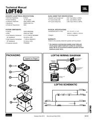
Install the Remote Level Control in a<br />
convenient location in or under the<br />
dashboard. The control may be<br />
removed from its housing for custom<br />
installation. Using the enclosed RJ11<br />
cable, connect the control to the<br />
amplifier, as shown in Figure 1.<br />
RJ11 Cable<br />
A6000GTi/A3000GTi<br />
(on input panel)<br />
RJ45 connector<br />
Figure 1. Connecting the Remote Level<br />
Control.<br />
Once the amplifier is mounted, peel the<br />
backing from the adhesive (on the back<br />
of the logo badge) and attach the<br />
badge in the appropriate orientation.<br />
2
DESIGNING A SPEAKER SYSTEM FOR THE GTi AMPLIFIER<br />
NOTE: Although the <strong>JBL</strong> A6000GTi or<br />
A3000GTi amplifier will drive a system<br />
made up of any subwoofers, we<br />
re<strong>com</strong>mend using <strong>JBL</strong> GTi subwoofers<br />
with GTi amplifiers.<br />
Both the <strong>JBL</strong> A6000GTi and A3000GTi<br />
amplifiers provide RMS power that<br />
exceeds the RMS power-handling<br />
rating of nearly every subwoofer<br />
available. To use this amplifier<br />
optimally, you should design a speaker<br />
system made up of several identical<br />
speakers, so that the power delivered<br />
by the amplifier will be shared equally<br />
among the speakers.<br />
The <strong>JBL</strong> A6000GTi and A3000GTi<br />
amplifiers support a wide range of<br />
impedances, and any speaker system<br />
with a total or equivalent impedance of<br />
1 to 4 ohms will extract full power from<br />
either amplifier. In order to connect<br />
multiple woofers to the A6000GTi or<br />
A3000GTi, you’ll need to connect your<br />
speakers in series, parallel or seriesparallel.<br />
We’ve included diagrams for<br />
each connection scheme and a pair of<br />
formulas, which will help you.<br />
SERIES CONNECTIONS<br />
The formula for determining the<br />
total impedance of the two woofers<br />
connected in series is:<br />
Z total = Z 1 + Z 2 + Z 3 ...<br />
Where Z total is the total impedance of<br />
all woofers connected in series. Z 1 , Z 2<br />
and Z 3 (and so on) are the nominal<br />
impedance ratings of the individual<br />
speakers. The total impedance of the<br />
voice coils shown in Figure 2 is 8 ohms.<br />
4 ohms 4 ohms<br />
PARALLEL<br />
CONNECTIONS<br />
The formula for determining the<br />
equivalent impedance of the voice<br />
coils connected in parallel is:<br />
Z equivalent = 1/(1/Z 1 + 1/Z 2 + 1/Z 3 …)<br />
Where Z equivalent is the equivalent<br />
impedance of the coils connected in<br />
parallel. Z 1 , Z 2 and Z 3 (and so on) are<br />
the nominal impedance ratings of the<br />
individual speakers. The equivalent<br />
impedance of the voice coils shown in<br />
Figure 3 is 2 ohms.<br />
4 ohms 4 ohms<br />
Figure 3. Parallel connection of two<br />
4-ohm voice coils yields a total<br />
impedance of 2 ohms.<br />
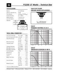
DUAL VOICE-COIL<br />
CONNECTIONS<br />
Dual voice-coil subwoofers, such as<br />
<strong>JBL</strong>’s GTi series, may be connected<br />
in series, as shown in Figure 2; in<br />
parallel, as shown in Figure 3; or in<br />
series-parallel, as shown in Figure 4.<br />
Figure 4. Series-parallel connections<br />
of three W15GTi subwoofers (with a<br />
voice coil impedance of 6 ohms) yields<br />
a total series impedance of 12 ohms<br />
for each subwoofer, and an equivalent<br />
parallel impedance of 4 ohms for all<br />
three subwoofers.<br />
To determine the impedance of a<br />
system of three W15GTi (dual voicecoil)<br />
subwoofers connected in seriesparallel,<br />
use the series connection<br />
formula to determine the impedance<br />
of each subwoofer with its voice coils<br />
connected in series. Then insert the<br />
calculated value into the parallel<br />
connection formula to determine the<br />
equivalent impedance for the three<br />
subwoofers connected in parallel.<br />
NOTE: Each W15GTi voice coil has an<br />
impedance of 6 ohms.<br />
For example, in Figure 4, each woofer<br />
will have an impedance of 12 ohms, by<br />
Z total = Z 1 + Z 2 = 6 + 6 = 12<br />
and the three woofers connected<br />
in parallel will have an equivalent<br />
impedance of 4 ohms, by<br />
Z equivalent = 1/(1/Z 1 + 1/Z 2 + 1/Z 3 )<br />
= 1/(1/12 + 1/12 + 1/12)<br />
= 1/(3/12)<br />
= 12/3 = 4<br />
NOTE: All subwoofers connected to an<br />
amplifier in a system must be identical<br />
and, if they are dual voice-coil subwoofers,<br />
their coils must be wired<br />
identically. Do not connect the coils of<br />
one subwoofer together in series and<br />
another in parallel, since doing so will<br />
cause uneven power distribution,<br />
potential damage to the speakers, and<br />
poor overall performance.<br />
Remove<br />
Terminal Jumper<br />
ABOUT SPEAKER<br />
POWER HANDLING<br />
The RMS power handling rating of<br />
a speaker indicates the amount of<br />
power it will handle continuously.<br />
Although designing a subwoofer<br />
system by considering the RMS rating<br />
will ultimately provide you with the<br />
most reliable system, your speakers<br />
may be able to handle more power,<br />
depending on what kind of music is<br />
being reproduced.<br />
For music with extended bass notes<br />
(e.g., bass music, hip-hop or techno),<br />
you should design a speaker system<br />
based on the RMS power handling of<br />
your speakers. For music with sharp<br />
transient bass notes (e.g., rock,<br />
country or jazz), the RMS power<br />
handling rating is conservative, and<br />
you can count on your speakers being<br />
able to handle more power than the<br />
RMS rating.<br />
The total power output of your<br />
amplifier will be divided among the<br />
speakers connected to it. For example,<br />
if you are using an A6000GTi and three<br />
W15GTi subwoofers, each subwoofer<br />
will receive 2,000 watts.<br />
It’s important to choose a system of<br />
subwoofers that will handle all of the<br />
power. To determine how much total<br />
power your speaker system will<br />
handle, simply multiply the RMS power<br />
handling rating of one of your speakers<br />
by the total number of speakers that<br />
will be connected.<br />
Red<br />
Figure 2. Series connection of two<br />
4-ohm voice coils yields a total<br />
impedance of 8 ohms.<br />
Black<br />
Remove<br />
Terminal Jumper<br />
3
SUPPLYING POWER TO THE GTi AMPLIFIER<br />
POWER IN IS<br />
POWER OUT<br />
In order to get full power out of your<br />
amplifier, you must provide full power<br />
to your amplifier. That’s a basic rule<br />
of physics. The A6000GTi amplifier<br />
can draw nearly 800 amperes when<br />
reproducing sine waves at full output.<br />
Both <strong>JBL</strong> A6000GTi and A3000GTi<br />
amplifiers can quickly exhaust the<br />
factory-installed charging system of<br />
any vehicle on the road today. With<br />
this much available amplifier power,<br />
you will need to beef up your vehicle’s<br />
electrical system to satisfy the<br />
amplifier’s current demands. We<br />
re<strong>com</strong>mend adding at least two<br />
12-volt batteries, connected in<br />
parallel with cold-cranking capacities<br />
of at least 600 amperes each, to the<br />
factory-installed charging system.<br />
HOW YOUR CHARGING<br />
SYSTEM WORKS<br />
The battery’s job is to start your<br />
vehicle. Running the electrical<br />
accessories is the alternator’s job.<br />
The battery isn’t designed to be a<br />
continuous source of power. It is a<br />
renewable source and is charged by<br />
the alternator when the engine runs.<br />
Battery charging can only occur when<br />
the current demand from the electrical<br />
accessories is less than the total current<br />
output capacity of the alternator.<br />
PROGRAM MATERIAL<br />
AND CURRENT DEMAND<br />
Music is a <strong>com</strong>bination of loud and<br />
soft sounds, with varying durations<br />
and rhythms that present unique<br />
current demands during amplification.<br />
For example, it may take full power<br />
to reproduce the sound of a kick drum.<br />
The peak power demand doesn’t last<br />
very long, but it is repeated over<br />
and over.<br />
If your charging system can’t provide<br />
all the power your amplifier needs on<br />
a continuous basis, it still may be<br />
adequate. During the sound of the<br />
kick drum, the battery can provide<br />
the extra current that’s necessary,<br />
and between kick drum beats, the<br />
alternator will put some of the energy<br />
back into the battery.<br />
Few stock batteries can provide the<br />
current required to reproduce even<br />
short-duration musical peaks. Adding<br />
a pair of batteries with cold-cranking<br />
capacities of 600 amperes will provide<br />
extra current for short music bursts,<br />
but reserve power may still be<br />
depleted over longer music intervals.<br />
Adding more batteries will provide<br />
more reserve power and current, but<br />
no matter how many are installed, the<br />
alternator will still have to recharge<br />
them all.<br />
If you plan to use the A6000GTi or<br />
A3000GTi in SPL <strong>com</strong>petition, the<br />
charging system requirements will be<br />
much greater than those for normal<br />
music listening. Be prepared to add<br />
additional batteries and alternators to<br />
provide continuous current required<br />
for continuous duty.<br />
However, depending on the current<br />
rating of the alternator, the amplifier’s<br />
maximum output power, the music<br />
content, and the charging system’s<br />
capability, the alternator may not be<br />
able to keep up over time. In that case,<br />
you’ll need to install a somewhat larger<br />
alternator for more current, or adjust<br />
your driving and listening habits, to<br />
give the alternator time to catch up<br />
with the amplifier’s current demand.<br />
See your authorized <strong>JBL</strong> car audio<br />
dealer for help in designing and<br />
installing an upgraded charging<br />
system to support your GTi amplifier.<br />
4
MAKING THE CONNECTIONS<br />
POWER CONNECTIONS<br />
Use 0-gauge cable to connect the<br />
amplifier’s GND – terminal directly to<br />
the vehicle’s chassis (see Figure 5).<br />
Scrape off all paint from the metal area<br />
for a good, clean ground connection.<br />
Make sure the ground wire is as short<br />
as possible and is connected to metal<br />
on the vehicle’s body. Do not connect<br />
the GND – cable to the frame of the<br />
vehicle. It is isolated from the chassis<br />
using rubber shims and will not provide<br />
an adequate ground. Instead, use the<br />
trunk’s floor or cargo area as a suitable<br />
location. Do not connect the GND –<br />
cable to the battery’s negative (–)<br />
terminal.<br />
(or other<br />
turn-on<br />
signal)<br />
Ground<br />
Source Unit<br />
+12 V<br />
85<br />
87 87a<br />
no nc<br />
86 30<br />
SPDT Relay<br />
Remote Turn-On<br />
Figure 5. Power wiring<br />
diagram for the <strong>JBL</strong> A6000GTi<br />
amplifier. The A3000GTi is<br />
wired in a similar way.<br />
ANN-Type Fuse<br />
(500 A or more)<br />
Use 0-gauge cable to connect the<br />
BATT+ terminal directly to the vehicle’s<br />
battery. If the battery is located in the<br />
engine <strong>com</strong>partment and the BATT+<br />
cable must be routed through the<br />
firewall or any metal obstruction,<br />
install a wafer-type (ANN) fuse with a<br />
current rating of at least 500 amperes<br />
and an appropriate fuse holder<br />
within 18" of the vehicle’s battery<br />
(see Figure 5).<br />
Connect the source unit’s remote<br />
turn-on lead to the REMOTE terminal<br />
on the amplifier (see Figure 5). Use<br />
any convenient gauge wire for the<br />
connection.<br />
The amplifier’s internal neon lights<br />
require a separate switched power<br />
connection with at least a 2-ampere<br />
current capacity. If desired, install a<br />
switch to turn on the neon lights or a<br />
relay triggered by a circuit in the vehicle<br />
(e.g., door switch, trunk pin switch or<br />
other turn-on source). If you want the<br />
amplifier’s neon to light when the<br />
amplifier is on, connect the LIGHTING<br />
terminal to a relay triggered by the radio’s<br />
remote turn-on lead (see Figure 5).<br />
18"<br />
Batteries<br />
A6000GTi<br />
Power Terminals<br />
0-gauge<br />
0-gauge<br />
Chassis<br />
Ground<br />
(Bare Metal)<br />
IMPORTANT: Do not connect a jumper<br />
directly between the REMOTE and<br />
LIGHTING terminals. Doing so may<br />
burn out the remote turn-on circuits<br />
in your source unit.<br />
SIGNAL CONNECTIONS<br />
Use high-quality twisted-pair RCA<br />
audio cables to connect your source<br />
unit’s main stereo or subwoofer RCA<br />
output jacks to the amplifier’s L/R<br />
INPUT jacks. For a single subwoofer<br />
output, use an RCA “Y” adapter to<br />
connect its signal to both input jacks.<br />
As a convenience, each <strong>JBL</strong> A6000GTi<br />
or A3000GTi amplifier is also equipped<br />
with a set of PASS-THRU L/R RCA<br />
audio jacks. They will pass in<strong>com</strong>ing<br />
audio signals unaltered, and you can<br />
use them to send stereo audio signals<br />
to other <strong>com</strong>ponents in your system.<br />
REMOTE LEVEL<br />
CONTROL/ACCESSORY<br />
GAUGE OUTPUTS<br />
The A6000GTi and A3000GTi use an<br />
RJ45 connector to output control<br />
signals for the Remote Level Control<br />
and accessory gauges. Use the 15'<br />
RJ11 cable to connect the control to<br />
the amplifier. For accessory gauges,<br />
use the pinouts in Figure 6 to make<br />
custom cables with materials found<br />
at most electronics supply stores or<br />
home centers.<br />
RJ45 Connector<br />
(GTi Input Panel)<br />
Ground (also use for acc. gauges) = 8<br />
No Connection = 7<br />
Remote Level Control = 6<br />
Remote Level Control = 5<br />
8 1<br />
For gauges, varying voltages are output<br />
on selected RJ45 pins to indicate<br />
voltage, current and temperature.<br />
For battery voltage, linear scale (pin 1):<br />
2 volts = 8 volts at the battery<br />
4.5 volts = 18 volts at the battery<br />
For temperature, linear scale (pin 2):<br />
0 volts = –10 degrees Celsius<br />
5 volts = 110 degrees Celsius<br />
For current, linear scale (pin 3):<br />
0 volts = 0 amperes current draw<br />
5 volts = 800 amperes current draw<br />
Also, you can connect a power meter<br />
using the pins for battery voltage and<br />
current. Be sure to use a power meter<br />
that multiplies the in<strong>com</strong>ing voltage<br />
and current signals (i.e., P = E x I) to<br />
convert the data to watts.<br />
CONNECTING<br />
THE SPEAKERS<br />
IMPORTANT: As a safety feature<br />
and due to the high output voltage<br />
capability of the A6000GTi and<br />
A3000GTi amplifiers, the SPEAKER<br />
OUTPUTS are equipped with a cover<br />
that must be in place in order for the<br />
amplifier to operate. When the cover<br />
is removed, the amplifier will turn off<br />
and speaker connections can be<br />
made safely.<br />
1 = Battery Voltage (to acc. volt meter)<br />
2 = Temperature (to acc. temp. gauge)<br />
3 = Current (to acc. ampere meter)<br />
4 = Remote Level Control<br />
Figure 6. Pinouts for the REMOTE LEVEL RJ45 connector on the<br />
A6000GTi or A3000GTi amplifier.<br />
5
MAKING THE CONNECTIONS<br />
A6000GTi SPEAKER<br />
CONNECTIONS<br />
The A6000GTi is a 2-channel amplifier<br />
designed to drive subwoofers only.<br />
The left and right input signals are<br />
<strong>com</strong>bined inside the amplifier to<br />
provide a mono output signal, no<br />
matter which output mode is selected.<br />
Figure 7. The <strong>JBL</strong> A6000GTi<br />
subwoofer amplifier is set<br />
to bridged mode to drive a<br />
subwoofer system. Only use<br />
this mode when the nominal<br />
equivalent or total impedance<br />
of the speaker system is<br />
2 ohms or greater.<br />
Set Output Mode<br />
to 2CH/BR<br />
(on input panel)<br />
A6000GTi Amplifier<br />
(partial output panel)<br />
The A6000GTi can be connected to<br />
two independent speaker systems in<br />
2-channel mode. It can be connected<br />
to a <strong>com</strong>bination of subwoofers<br />
configured as a single load with its<br />
channels bridged or connected in<br />
parallel. Bridged channels will provide<br />
high output voltage for driving loads<br />
with a nominal impedance of 2 to 4<br />
ohms. Connecting the channels in<br />
parallel will provide the high current<br />
necessary to drive loads of 1 to 2 ohms.<br />
Included below are three application<br />
diagrams that will help you plan<br />
your A6000GTi installation. Figures 7<br />
through 9 show how to configure the<br />
<strong>JBL</strong> A6000GTi subwoofer amplifier for<br />
bridged-mono, parallel-mono and<br />
2-channel operation (see Setting Up<br />
the GTi Amplifier).<br />
Figure 8. The <strong>JBL</strong> A6000GTi<br />
subwoofer amplifier is set<br />
to parallel mode to drive a<br />
subwoofer system. Only<br />
use this mode when the<br />
nominal equivalent or total<br />
impedance of the speaker<br />
system is less than 2 ohms.<br />
NOTE: A jumper is added<br />
between the + terminals.<br />
See “Setting The Crossover”<br />
on Page 8<br />
to Adjust Crossover Controls<br />
Set Output Mode<br />
to PARALLEL<br />
(on input panel)<br />
See “Setting The Crossover”<br />
on Page 8<br />
to Adjust Crossover Controls<br />
Subwoofer<br />
System<br />
2 ohms<br />
or more<br />
A6000GTi Amplifier<br />
(partial output panel)<br />
jumper<br />
Subwoofer<br />
System<br />
IMPORTANT: If the nominal impedance<br />
of the speaker system is close to 2<br />
ohms, you may try both bridged and<br />
parallel configurations to determine<br />
which one performs better. Remember<br />
to set the output mode switch to the<br />
appropriate setting when changing<br />
configurations.<br />
NOTE: For simplicity, Figures 7 through<br />
9 do not show power, remote and input<br />
connections (see page 5).<br />
Figure 9. The <strong>JBL</strong> A6000GTi<br />
subwoofer amplifier is set<br />
to 2-channel mode to drive<br />
a pair of subwoofers or<br />
subwoofer systems with<br />
nominal equivalent or total<br />
impedances of 2 to 4 ohms.<br />
Set Output Mode<br />
to 2CH/BR<br />
(on input panel)<br />
2 ohms<br />
or less<br />
A6000GTi Amplifier<br />
(partial output panel)<br />
See “Setting The Crossover”<br />
on Page 8<br />
to Adjust Crossover Controls<br />
Subwoofer<br />
System<br />
Subwoofer<br />
System<br />
2 to 4<br />
ohms<br />
2 to 4<br />
ohms<br />
6
MAKING THE CONNECTIONS<br />
A3000GTi SPEAKER<br />
CONNECTIONS<br />
Included below are three application<br />
diagrams that will help you plan your<br />
A3000GTi installation. Figures 10<br />
through 12 show how to configure<br />
the <strong>JBL</strong> A3000GTi amplifier for<br />
bridged-mono, parallel-mono and<br />
2-channel operation (also see<br />
Setting Up the GTi Amplifier).<br />
NOTE: For simplicity, Figures 10<br />
through 12 do not show power, remote<br />
and input connections (see page 5).<br />
Figure 10. The <strong>JBL</strong> A3000GTi<br />
amplifier is set to bridged<br />
mode to drive a subwoofer<br />
system. Only use this mode<br />
when the nominal equivalent<br />
or total impedance of the<br />
speaker system is 2 ohms<br />
or greater.<br />
Set Output Mode<br />
to BRIDGE<br />
(on input panel)<br />
See “Setting The Crossover”<br />
on Page 8<br />
to Adjust Crossover Controls<br />
A3000GTi Amplifier<br />
(partial output panel)<br />
Subwoofer<br />
System<br />
OUTPUT LOAD SWITCH<br />
The Output Load switch is used to<br />
optimize amplifier performance when<br />
driving a full-range signal. Set the<br />
switch according to the nominal<br />
impedance of the load: Use the<br />
4-ohm mode when driving loads<br />
with a nominal impedance greater<br />
than 2 ohms and the 2-ohm mode<br />
when driving loads with a nominal<br />
impedance of 2 ohms or less.<br />
Figure 11. The <strong>JBL</strong> A3000GTi<br />
amplifier is set to parallel<br />
mode to drive a subwoofer<br />
system. Only use this mode<br />
when the nominal equivalent<br />
or total impedance of the<br />
speaker system is less than<br />
2 ohms.<br />
Set Output Mode<br />
to PARALLEL<br />
(on input panel)<br />
2 ohms<br />
or more<br />
A3000GTi Amplifier<br />
(partial output panel)<br />
jumper<br />
NOTE: A jumper is added<br />
between the + terminals.<br />
See “Setting The Crossover”<br />
on Page 8<br />
to Adjust Crossover Controls<br />
Subwoofer<br />
System<br />
2 ohms<br />
or less<br />
Figure 12. The <strong>JBL</strong> A3000GTi<br />
amplifier is set to stereo<br />
mode to drive a pair of fullrange<br />
speaker systems with<br />
nominal equivalent or total<br />
impedances of 2 to 4 ohms.<br />
Set Output Mode<br />
to STEREO<br />
(on input panel)<br />
A3000GTi Amplifier<br />
(partial output panel)<br />
See “Setting The Crossover”<br />
on Page 8<br />
to Adjust Crossover Controls<br />
L Speaker<br />
System<br />
R Speaker<br />
System<br />
2 to 4<br />
ohms<br />
2 to 4<br />
ohms<br />
7
SETTING UP THE GTi AMPLIFIER<br />
SETTING THE CROSSOVER<br />
IMPORTANT: If you plan to use the<br />
A3000GTi to drive full-range speakers,<br />
set the crossover mode switch to FLAT<br />
and skip to the next section, “Setting<br />
Input Sensitivity.”<br />
1. Depending on your system plan,<br />
set the A3000GTi’s crossover mode<br />
switch to LP (low-pass) or HP (highpass).<br />
The A6000GTi is a low-pass<br />
amplifier only, designed to drive<br />
subwoofers. No crossover switch<br />
is provided.<br />
2. The crossover slope has two<br />
settings: 12 (dB per octave) or<br />
24 (dB per octave). Select the<br />
slope that best suits your taste, but<br />
consider that a steeper low-pass<br />
filter will make the subwoofers<br />
sound less directional (since more<br />
midrange will be filtered from the<br />
signal). A steeper high-pass filter<br />
will reduce a small speaker’s<br />
unnecessary cone excursion at<br />
the lowest frequencies, which<br />
will increase power handling<br />
and reduce distortion.<br />
3. Set the A3000GTi’s HP FREQ control<br />
to allow the speakers to make<br />
as much bass as possible while<br />
minimizing distortion caused by<br />
small speakers trying to reproduce<br />
the lowest frequencies. The best<br />
setting is one where the speakers<br />
produce crisp, clear impact without<br />
being overdriven.<br />
4. For either amplifier, set the LP FREQ<br />
control so vocal information is not<br />
reproduced by the subwoofers, and<br />
the subwoofers’ sound blends with<br />
the sound of the midrange speakers<br />
without any missing information.<br />
NOTE: The LP FREQ control can be<br />
set to any frequency between 32Hz<br />
and 320Hz.<br />
SETTING INPUT<br />
SENSITIVITY<br />
NOTE: You can use the supplied<br />
REMOTE LEVEL control to fine-tune<br />
the input sensitivity or to adjust the<br />
level of the bass according to the<br />
program material after the amplifier’s<br />
LEVEL control has been set properly.<br />
Connect the remote module’s attached<br />
cable to the REMOTE LEVEL (RJ45) jack<br />
on the amplifier’s input panel. Start<br />
with the REMOTE LEVEL Control in its<br />
maximum (clockwise) position.<br />
1. Initially, turn the amplifier’s LEVEL<br />
control to the minimum (clockwise)<br />
position.<br />
2. Reconnect the (–) negative lead to<br />
your vehicle’s battery. Apply power<br />
to the audio system and play a<br />
favorite music track.<br />
3. Increase the source unit’s volume<br />
control to the maximum listening<br />
position. Slowly turn the amplifier’s<br />
LEVEL control counterclockwise and<br />
observe the I/OPT and E/OPT LEDs<br />
(on the amplifier’s top).<br />
• In the bridged or 2-channel mode,<br />
at the ideal setting, the E/OPT LED<br />
should flash on musical peaks to<br />
indicate the amplifier is producing<br />
maximum voltage. If the I/OPT LED<br />
flashes in bridged mode, this<br />
indicates the speaker system’s<br />
impedance is lower than 2 ohms<br />
and the amplifier should be<br />
configured in the parallel mode.<br />
• In the parallel mode, at the ideal<br />
setting, the I/OPT LED should<br />
flash on musical peaks to indicate<br />
that the amplifier is producing<br />
maximum current.<br />
If either the I/OPT or E/OPT LED is<br />
on steadily, the amplifier is being<br />
overdriven and your speakers may<br />
be in jeopardy. Turn the LEVEL<br />
control back slightly until the I/OPT or<br />
E/OPT LED flashes on musical peaks.<br />
SETTING PHASE<br />
1. Initially set the PHASE control to 0.°<br />
Play a favorite audio track that has<br />
significant bass output.<br />
2. Continue listening to the music and<br />
have another person slowly adjust<br />
the PHASE control towards 180° and<br />
back to 0° again.<br />
3. Repeat Step 2 as needed until you<br />
find a setting that produces the<br />
most mid-bass output.<br />
NOTE: For applications using multiple<br />
GTi amplifiers where the highest SPL<br />
is desired at a single point in the<br />
vehicle (i.e., SPL <strong>com</strong>petition), adjust<br />
the PHASE controls on all amplifiers<br />
so all speakers are in phase at the<br />
microphone position. This will provide<br />
the highest SPL when measured with<br />
an SPL meter.<br />
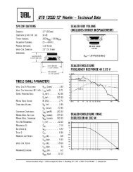
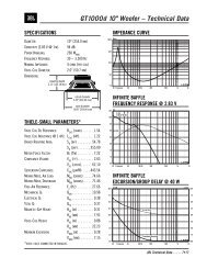
DBO HP FREQ Control<br />
(adjusts cut-off<br />
frequency)<br />
dB<br />
0<br />
–3<br />
–6<br />
–9<br />
–12<br />
20 80 Freq. (Hz)<br />
DBO BOOST Control<br />
(adjusts boost amount<br />
at cut-off frequency)<br />
dB<br />
12<br />
6<br />
0<br />
–6<br />
–12<br />
HP FREQ<br />
80Hz<br />
BOOST<br />
MIN<br />
20Hz<br />
MAX<br />
20 80 Freq. (Hz)<br />
Figure 13. Frequency response curves<br />
show typical DBO control ranges for<br />
the <strong>JBL</strong> A6000GTi or A3000GTi amplifier.<br />
SETTING DBO<br />
DBO (or Dynamic Bass Optimizer) is<br />
a 12dB/octave high-pass filter with<br />
variable frequency (20Hz to 80Hz)<br />
and variable boost (0 to +12dB) at<br />
the cutoff frequency.<br />
NOTE: During DBO adjustment, you can<br />
audition the effect by setting the DBO<br />
switch to OFF and then back to ON.<br />
NOTE: The A3000GTi can be used<br />
to drive a pair of stereo mid-bass<br />
speakers. In this case, use the DBO<br />
to set the high-pass filter (from 20Hz to<br />
80Hz) and use the crossover to set the<br />
low-pass filter (from 80Hz to 320Hz).<br />
For a vented box where a subwoofer<br />
is prone to overexcursion below the<br />
tuned frequency, set DBO to ON and<br />
set the DBO HP FREQ control 10Hz<br />
below the box’s resonant (tuned)<br />
frequency (e.g., 30Hz for a vented<br />
box tuned to 40Hz). Power typically<br />
wasted in this region will now be<br />
conserved and instead be available<br />
for frequencies the enclosure can<br />
reproduce. Use the DBO BOOST<br />
control to boost the bass at the set<br />
frequency by as much as 12dB, as<br />
shown in Figure 13.<br />
For a sealed enclosure, use DBO to<br />
enhance the middle of the bass region.<br />
Set DBO to ON, and then set the DBO<br />
HP FREQ control to 35Hz to 40Hz.<br />
Adjust the DBO BOOST control for a<br />
big and full bass sound. Alternatively,<br />
for a tighter-sounding bass, set the<br />
DBO HP FREQ control between 45Hz to<br />
50Hz and also adjust the DBO BOOST<br />
control according to your preference.<br />
For an infinite baffle application,<br />
set DBO to ON, and then set the<br />
HP FREQ control to the speaker’s Fs<br />
value (to keep the subwoofer from<br />
trying to create bass below the<br />
resonant frequency). Adjust the DBO<br />
BOOST control according to your taste.<br />
8
SETTING UP THE GTi AMPLIFIER<br />
REPLACING THE FUSE<br />
OR NEON TUBES<br />
The <strong>JBL</strong> A6000/A3000GTi amplifier<br />
is equipped with an internal fuse, a<br />
20-inch neon tube and two 6-inch neon<br />
tubes. Should the fuse or a neon tube<br />
fail, perform the following steps<br />
to replace the part:<br />
Figure 14. Removing bottom screws<br />
and the clear cover from the A6000GTi<br />
amplifier. NOTE: Do not remove the<br />
logo badge assembly.<br />
NOTE: For neon tube replacement, see<br />
your authorized <strong>JBL</strong> car audio dealer<br />
to purchase new StreetGlow ® neon<br />
tubes in 6- or 20-inch sizes.<br />
NOTE: Although the following<br />
steps discuss and illustrate how<br />
to disassemble a <strong>JBL</strong> A6000GTi,<br />
the disassembly procedure for a<br />
<strong>JBL</strong> A3000GTi is similar.<br />
1. Disconnect and unmount the<br />
amplifier from the vehicle. On a<br />
soft surface, turn the amplifier over<br />
to view the bottom. Using a T-25<br />
screwdriver, remove the four large<br />
Torx-head screws along the bottom<br />
edges and set them aside (see<br />
Figure 14).<br />
2. Turn the amplifier over to view the<br />
top. Using a 5 ⁄32-inch Allen wrench,<br />
remove the four cap screws on the<br />
clear cover and set them aside (see<br />
Figure 14).<br />
3. Slide the clear cover off and set it<br />
aside (see Figure 14).<br />
4. Using a T-15 screwdriver, remove<br />
the four Torx-head screws around<br />
the output panel and set them aside<br />
(see Figure 15).<br />
5. Repeat Step 4 for the input panel<br />
(see Figure 15).<br />
6. Remove the cover and set it aside<br />
(see Figure 15).<br />
Figure 15. Removing the input and<br />
output screws and the cover from the<br />
A6000GTi amplifier.<br />
9
SETTING UP THE GTi AMPLIFIER<br />
7. Using a T-15 screwdriver, remove<br />
the two Torx-head screws on the<br />
display board and set them aside<br />
(see Figure 16 below). Disconnect<br />
the ribbon cable from display board.<br />
8. Using a T-15 screwdriver, remove<br />
the 16 Torx-head screws on the<br />
perforated shield and set them aside<br />
(see Figure 16).<br />
Figure 16. Removing the fuse from the<br />
A6000GTi amplifier.<br />
9. Using a small flat-blade screwdriver,<br />
disconnect the wiring for the neon<br />
tubes.<br />
10. Remove the perforated shield and<br />
set it aside.<br />
11. Replace the fuse or a neon tube as<br />
follows:<br />
• To replace the fuse on the amplifier<br />
circuit board (see Figure 16),<br />
use a 7⁄16-inch hex-socket driver<br />
to remove the two fuse nuts and<br />
then discard the failed fuse.<br />
Fasten the replacement fuse<br />
in place using the two fuse nuts.<br />
• To replace a neon tube (see<br />
Figure 17), use a T-15 screwdriver<br />
and pliers to remove the two<br />
Torx-head screws, nuts and<br />
washers on the two clamps that<br />
hold each neon tube in place.<br />
Remove the failed neon tube<br />
and unscrew its wires.<br />
On the replacement neon tube, clip off<br />
the cigarette lighter adapter. Then strip<br />
the wires and screw the ends to the<br />
connector. Refasten the two clamps<br />
with hardware in place around the<br />
neon tube. If needed, repeat this procedure<br />
for another failed neon tube.<br />
Failed<br />
Fuse<br />
Figure 17. Neon tube locations on the<br />
A6000GTi amplifier.<br />
6" Neon Tubes<br />
12. Reassemble the amplifier in reverse<br />
order, as discussed in Steps 1<br />
through 10.<br />
20" Neon Tube<br />
(under shield)<br />
10
TROUBLESHOOTING<br />
SYMPTOM LIKELY CAUSE SOLUTION<br />
No audio No voltage at power Check BATT+, REMOTE and<br />
(Power LED is off) or remote terminal GND – terminals with VOM for<br />
blown fuse or poor connection<br />
A6000GTi<br />
Power<br />
6000 Watts Parallel Bridge<br />
Thermal Signal -18 dB -9 dB E Opt I Opt Fault<br />
Internal fuse blown<br />
Replace internal fuse<br />
(incorrect power<br />
(see Replacing the Fuse<br />
connections)<br />
or Neon Tubes section)<br />
No audio Low or high voltage Check BATT+ terminal with<br />
(Power LED at power terminal VOM for voltage between<br />
is flashing)<br />
10 and 16 Vdc; if not within<br />
limits, check vehicle’s<br />
electrical system<br />
No audio Direct current on Disconnect cable from<br />
(Power and speaker output(s) REMOTE terminal; if Fault LED<br />
Fault LEDs<br />
is still on, contact local <strong>JBL</strong><br />
are on)<br />
service center<br />
No audio Internal amplifier Check for blocked vents<br />
(Power and temperature is over or whether the ambient<br />
Thermal LEDs 85° C temperature is above 85° C<br />
are on)<br />
Distorted audio Amplifier’s gain is Properly adjust the<br />
(I OPT and/or set to High LEVEL control (see<br />
E OPT LED[s]<br />
Setting Input<br />
are on more<br />
Sensitivity section)<br />
than off)<br />
Distorted audio Defective source unit Try new source unit<br />
(I OPT and/or<br />
E OPT LED[s] Shorted speaker Disconnect wires from<br />
work correctly) wires SPEAKER OUTPUTS and<br />
check for shorts between<br />
wires, or between a wire and<br />
the vehicle’s chassis<br />
Music lacks Speakers are out Check speaker connections<br />
“punch” of phase (see sections on speaker<br />
connections)<br />
Wrong output mode<br />
Verify output mode setting<br />
(see Making the Connections<br />
section)<br />
Neon tubes do No voltage to neon tubes Check LIGHTING<br />
not light for +12 Vdc terminal with VOM<br />
A3000GTi<br />
3000 Watts Parallel Bridge<br />
CH 1<br />
Thermal<br />
Signal -18 dB -9 dB E Opt I Opt<br />
CH 2<br />
Figure 18. Display indicates Power Output and Protection status.<br />
Power<br />
Fault<br />
Neon tubes are dead<br />
Replace neon tubes<br />
(see Replacing the Fuse<br />
or Neon Tubes section)<br />
11
Features, specifications and appearance are subject to change without notice.<br />
<strong>JBL</strong> Consumer Products<br />
250 Crossways Park Drive, Woodbury, NY 11797 USA<br />
© 2004 Harman International Industries, Incorporated<br />
<strong>JBL</strong> and Crown are registered trademarks of<br />
Harman International Industries, Incorporated.<br />
Part No. GTIAMPOM4/04<br />
www.jbl.<strong>com</strong>