TD-W8961ND Wireless N ADSL2+ Modem Router - Mondo Plast
TD-W8961ND Wireless N ADSL2+ Modem Router - Mondo Plast
TD-W8961ND Wireless N ADSL2+ Modem Router - Mondo Plast

Create successful ePaper yourself
Turn your PDF publications into a flip-book with our unique Google optimized e-Paper software.
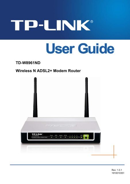
<strong>TD</strong>-<strong>W8961ND</strong><br />
<strong>Wireless</strong> N <strong>ADSL2+</strong> <strong>Modem</strong> <strong>Router</strong><br />
Rev: 1.0.1<br />
1910010351
COPYRIGHT & TRADEMARKS<br />
Specifications are subject to change without notice.<br />
is a registered trademark<br />
of TP-LINK TECHNOLOGIES CO., L<strong>TD</strong>. Other brands and product names are trademarks or<br />
registered trademarks of their respective holders.<br />
No part of the specifications may be reproduced in any form or by any means or used to make any<br />
derivative such as translation, transformation, or adaptation without permission from TP-LINK<br />
TECHNOLOGIES CO., L<strong>TD</strong>. Copyright © 2010 TP-LINK TECHNOLOGIES CO., L<strong>TD</strong>. All rights<br />
reserved.<br />
http://www.tp-link.com<br />
FCC STATEMENT<br />
This equipment has been tested and found to comply with the limits for a Class B digital device,<br />
pursuant to part 15 of the FCC Rules. These limits are designed to pro-vide reasonable protection<br />
against harmful interference in a residential installation. This equipment generates, uses and can<br />
radiate radio frequency energy and, if not in-stalled and used in accordance with the instructions,<br />
may cause harmful interference to radio communications. However, there is no guarantee that<br />
interference will not occur in a particular installation. If this equipment does cause harmful<br />
interference to radio or television reception, which can be determined by turning the equipment off<br />
and on, the user is encouraged to try to correct the interference by one or more of the following<br />
measures:<br />
• Reorient or relocate the receiving antenna.<br />
• Increase the separation between the equipment and receiver.<br />
• Connect the equipment into an outlet on a circuit different from that to which the<br />
receiver is connected.<br />
• Consult the dealer or an experienced radio/ TV technician for help.<br />
This device complies with part 15 of the FCC Rules. Operation is subject to the following two<br />
conditions:<br />
1) This device may not cause harmful interference.<br />
2) This device must accept any interference received, including interference that may<br />
cause undesired operation.<br />
Any changes or modifications not expressly approved by the party responsible for compliance<br />
could void the user’s authority to operate the equipment.<br />
Note: The manufacturer is not responsible for any radio or tv interference caused by unauthorized<br />
modifications to this equipment. Such modifications could void the user’s authority to operate the<br />
equipment.
FCC RF Radiation Exposure Statement<br />
This equipment complies with FCC RF radiation exposure limits set forth for an uncontrolled<br />
environment. This device and its antenna must not be co-located or operating in conjunction with<br />
any other antenna or transmitter.<br />
“To comply with FCC RF exposure compliance requirements, this grant is applicable to only<br />
Mobile Configurations. The antennas used for this transmitter must be installed to provide a<br />
separation distance of at least 20 cm from all persons and must not be co-located or operating in<br />
conjunction with any other antenna or transmitter.”<br />
CE Mark Warning<br />
This is a class B product. In a domestic environment, this product may cause radio interference, in<br />
which case the user may be required to take adequate measures.<br />
National Restrictions<br />
This device is intended for home and office use in all EU countries (and other countries following<br />
the EU directive 1999/5/EC) without any limitation except for the countries mentioned below:<br />
Country Restriction Reason/remark<br />
Bulgaria<br />
None<br />
General authorization required for outdoor use and<br />
public service<br />
France<br />
Outdoor use limited to 10<br />
mW e.i.r.p. within the band<br />
2454-2483.5 MHz<br />
Military Radiolocation use. Refarming of the 2.4 GHz<br />
band has been ongoing in recent years to allow current<br />
relaxed regulation. Full implementation planned 2012<br />
Italy<br />
None<br />
If used outside of own premises, general authorization is<br />
required<br />
Luxembourg<br />
None<br />
General authorization required for network and service<br />
supply(not for spectrum)<br />
Norway<br />
Implemented<br />
This subsection does not apply for the geographical area<br />
within a radius of 20 km from the centre of Ny-Ålesund<br />
Russian Federation None Only for indoor applications<br />
Note: Please don’t use the product outdoors in France.
TP-LINK TECHNOLOGIES CO., L<strong>TD</strong><br />
DECLARATION OF CONFORMITY<br />
For the following equipment:<br />
Product Description: <strong>Wireless</strong> N <strong>ADSL2+</strong> <strong>Modem</strong> <strong>Router</strong><br />
Model No.: <strong>TD</strong>-<strong>W8961ND</strong><br />
Trademark: TP-LINK<br />
We declare under our own responsibility that the above products satisfy all the technical<br />
regulations applicable to the product within the scope of Council Directives:<br />
Directives 1999/5/EC<br />
The above product is in conformity with the following standards or other normative documents<br />
ETSI EN 300 328 V1.7.1: 2006<br />
ETSI EN 301 489-1 V1.8.1:2008& ETSI EN 301 489-17 V2.1.1:2009<br />
EN60950-1:2006<br />
Recommendation 1999/519/EC<br />
EN62311:2008<br />
Directives 2004/108/EC<br />
The above product is in conformity with the following standards or other normative documents<br />
EN 55022:2006 +A1:2007<br />
EN 55024:1998+A1:2001+A2:2003<br />
EN 61000-3-2:2006<br />
EN 61000-3-3:1995+A1:2001+A2:2005<br />
Directives 2006/95/EC<br />
The above product is in conformity with the following standards or other normative documents<br />
EN60950-1:2006<br />
Directive(ErP) 2009/125/EC<br />
Audio/Video, information and communication technology equipment- Environmentally conscious<br />
design<br />
EN62075:2008<br />
Person is responsible for marking this declaration:<br />
Yang Hongliang<br />
Product Manager of International Business<br />
TP-LINK TECHNOLOGIES CO., L<strong>TD</strong>.<br />
South Building, No.5 Keyuan Road, Central Zone, Science & Technology Park, Nanshan,<br />
Shenzhen, P. R. China
CONTENTS<br />
Package Contents .................................................................................................... 1<br />
Chapter 1 Introduction ......................................................................................... 2<br />
1.1 Product Overview.................................................................................. 2<br />
1.2 Main Features ....................................................................................... 2<br />
1.3 Conventions .......................................................................................... 3<br />
Chapter 2 Hardware Installation.......................................................................... 4<br />
2.1 The Front Panel .................................................................................... 4<br />
2.2 The Back Panel..................................................................................... 5<br />
2.3 Installation Environment........................................................................ 5<br />
2.4 Connecting the <strong>Router</strong> .......................................................................... 6<br />
Chapter 3 Quick Installation Guide ..................................................................... 8<br />
3.1 Configure PC......................................................................................... 8<br />
3.2 Login ................................................................................................... 11<br />
Chapter 4 Software Configuration .................................................................... 14<br />
4.1 Status.................................................................................................. 14<br />
4.1.1 Device Info............................................................................................... 14<br />
4.1.2 System Log.............................................................................................. 15<br />
4.1.3 Statistics .................................................................................................. 16<br />
4.2 Quick Start .......................................................................................... 18<br />
4.3 Interface Setup.................................................................................... 18<br />
4.3.1 Internet .................................................................................................... 19<br />
4.3.2 LAN ......................................................................................................... 24<br />
4.3.3 <strong>Wireless</strong>................................................................................................... 27<br />
4.4 Advanced Setup.................................................................................. 37<br />
4.4.1 Firewall .................................................................................................... 37<br />
4.4.2 Routing .................................................................................................... 38<br />
4.4.3 NAT ......................................................................................................... 39<br />
4.4.4 QoS ......................................................................................................... 42<br />
4.4.5 VLAN ....................................................................................................... 44<br />
4.4.6 ADSL ....................................................................................................... 46<br />
4.5 Access Management........................................................................... 47<br />
4.5.1 ACL ......................................................................................................... 47<br />
4.5.2 Filter ........................................................................................................ 48
4.5.3 SNMP ...................................................................................................... 56<br />
4.5.4 UPnP ....................................................................................................... 56<br />
4.5.5 DDNS ...................................................................................................... 57<br />
4.5.6 CWMP ..................................................................................................... 57<br />
4.6 Maintenance........................................................................................ 58<br />
4.6.1 Administration.......................................................................................... 58<br />
4.6.2 Time Zone ............................................................................................... 59<br />
4.6.3 Firmware.................................................................................................. 60<br />
4.6.4 System Restart ........................................................................................ 62<br />
4.6.5 Diagnostic................................................................................................ 62<br />
4.7 Help..................................................................................................... 63<br />
Appendix A: Specifications................................................................................... 65
Package Contents<br />
The following contents should be found in your package:<br />
‣ One <strong>TD</strong>-<strong>W8961ND</strong> <strong>Wireless</strong> N <strong>ADSL2+</strong> <strong>Modem</strong> <strong>Router</strong><br />
‣ One Power Adapter for <strong>TD</strong>-<strong>W8961ND</strong> <strong>Wireless</strong> N <strong>ADSL2+</strong> <strong>Modem</strong> <strong>Router</strong><br />
‣ Quick Installation Guide<br />
‣ One RJ45 cable<br />
‣ Two RJ11 cables<br />
‣ One ADSL splitter<br />
‣ One Resource CD, which includes this User Guide<br />
Note:<br />
Make sure that the package contains the above items. If any of the listed items are damaged or<br />
missing, please contact your distributor.<br />
1
<strong>TD</strong>-<strong>W8961ND</strong> <strong>Wireless</strong> N <strong>ADSL2+</strong> <strong>Modem</strong> <strong>Router</strong> User Guide<br />
Chapter 1 Introduction<br />
Thank you for choosing the <strong>TD</strong>-<strong>W8961ND</strong> <strong>Wireless</strong> N <strong>ADSL2+</strong> <strong>Modem</strong> <strong>Router</strong>.<br />
1.1 Product Overview<br />
The device is designed to provide a simple and cost-effective ADSL Internet connection for a<br />
private Ethernet or IEEE 802.11n/ IEEE 802.11g/ IEEE 802.11b wireless network.<br />
The <strong>TD</strong>-<strong>W8961ND</strong> connects to an Ethernet LAN or computers via standard Ethernet ports. The<br />
ADSL connection is made using ordinary telephone line with standard connectors. Multiple<br />
workstations can be networked and connected to the Internet using a single Wide Area Network<br />
(WAN) interface and single global IP address. The advanced security enhancements, IP/MAC<br />
Filter, Application Filter and URL Filter can help to protect your network from potentially<br />
devastating intrusions by malicious agents from the outside of your network.<br />
Quick Start of the Web-based Utility is supplied and friendly help messages are provided for the<br />
configuration. Network and <strong>Router</strong> management is done through the Web-based Utility which can<br />
be accessed through local Ethernet using any web browser.<br />
ADSL<br />
The <strong>TD</strong>-<strong>W8961ND</strong> supports full-rate <strong>ADSL2+</strong> connectivity conforming to the ITU and ANSI<br />
specifications. In addition to the basic DMT physical layer functions, the <strong>ADSL2+</strong> PHY supports<br />
dual latency <strong>ADSL2+</strong> framing (fast and interleaved) and the I.432 ATM Physical Layer.<br />
<strong>Wireless</strong><br />
In the most attentive wireless security, the <strong>Router</strong> provides multiple protection measures. It can be<br />
set to turn off the wireless network name (SSID) broadcast so that only stations that have the<br />
SSID can be connected. The <strong>Router</strong> provides wireless LAN 64/128-bit WEP encryption security,<br />
WPA-PSK/WPA2-PSK authentication, as well as TKIP/AES encryption security.<br />
1.2 Main Features<br />
‣ Four 10/100Mbps Auto-Negotiation RJ45 LAN ports (Auto MDI/MDIX), one RJ11 port.<br />
‣ Provides external splitter.<br />
‣ Adopts Advanced DMT modulation and demodulation technology.<br />
‣ Supports bridge mode and <strong>Router</strong> function.<br />
‣ Multi-user sharing a high-speed Internet connection.<br />
‣ Downstream data rates up to 24Mbps, upstream data rates up to 3.5Mbps(With Annex M<br />
enabled).<br />
‣ Supports long transfers, the max line length can reach to 6.5Km.<br />
‣ Supports remote configuration and management through SNMP and CWMP.<br />
‣ Supports PPPoE, it allows connecting the internet on demand and disconnecting from the<br />
2
<strong>TD</strong>-<strong>W8961ND</strong> <strong>Wireless</strong> N <strong>ADSL2+</strong> <strong>Modem</strong> <strong>Router</strong> User Guide<br />
Internet when idle.<br />
‣ Provides reliable ESD and surge-protect function with quick response semi-conductive surge<br />
protection circuit.<br />
‣ High speed and asymmetrical data transmit mode, provides safe and exclusive bandwidth.<br />
‣ Supports All ADSL industrial standards.<br />
‣ Compatible with all mainstream DSLAM (CO).<br />
‣ Provides integrated access of internet and route function which face to SOHO user.<br />
‣ Real-time Configuration and device monitoring.<br />
‣ Supports Multiple PVC (Permanent Virtual Circuit).<br />
‣ Built-in DHCP server.<br />
‣ Built-in firewall, supporting IP/MAC filter, Application filter and URL filter.<br />
‣ Supports Virtual Server, DMZ host and IP Address Mapping.<br />
‣ Supports Dynamic DNS, UPnP and Static Routing.<br />
‣ Supports system log and flow Statistics.<br />
‣ Supports firmware upgrade and Web management.<br />
‣ Provides WPA-PSK/WPA2-PSK data security, TKIP/AES encryption security.<br />
‣ Provides 64/128-bit WEP encryption security and wireless LAN ACL (Access Control List).<br />
1.3 Conventions<br />
The <strong>Router</strong> or device mentioned in this User Guide stands for <strong>TD</strong>-<strong>W8961ND</strong> without any<br />
explanations.<br />
Parameters provided in the pictures are just references for setting up the product, which may<br />
differ from the actual situation.<br />
3
<strong>TD</strong>-<strong>W8961ND</strong> <strong>Wireless</strong> N <strong>ADSL2+</strong> <strong>Modem</strong> <strong>Router</strong> User Guide<br />
Chapter 2 Hardware Installation<br />
2.1 The Front Panel<br />
Figure 2-1<br />
The LEDs locate on the front panel, they indicate the device’s working status. For details, please<br />
refer to LED Explanation.<br />
LED Explanation:<br />
Name Status Indication<br />
Power<br />
ADSL<br />
Internet<br />
WLAN<br />
LAN(1-4)<br />
QSS<br />
On<br />
Off<br />
Flash<br />
On<br />
Off<br />
Off<br />
On<br />
Flash<br />
On<br />
Flash<br />
Off<br />
Flash<br />
On<br />
Off<br />
Slow Flash<br />
On<br />
Quick Flash<br />
Power is on.<br />
Power is off.<br />
The ADSL negotiation is in progress.<br />
The LINE port is linked up.<br />
The LINE port is linked down.<br />
There is no successful PPP connection or the <strong>Router</strong> works on Bridge<br />
mode.<br />
A successful PPP connection has been built.<br />
Data is being transferred over the Internet.<br />
The wireless function is enabled but no data is being transmitted.<br />
There is wireless data being transmitted.<br />
The wireless function is disabled.<br />
Data is being transferred over the 1-4 (LAN) port.<br />
There is a successful connection on the corresponding 1-4 (LAN)<br />
port but no activity.<br />
There is no connection on the corresponding 1-4 (LAN) port or the<br />
connection is abnormal.<br />
A wireless device is connecting to the network by QSS function. This<br />
process will last in the first 2 minutes.<br />
A wireless device has been successfully added to the network by QSS<br />
function.<br />
A wireless device failed to be added to the network by QSS function.<br />
4
<strong>TD</strong>-<strong>W8961ND</strong> <strong>Wireless</strong> N <strong>ADSL2+</strong> <strong>Modem</strong> <strong>Router</strong> User Guide<br />
Note:<br />
After a device is successfully added to the network by QSS function, the QSS LED will keep on for<br />
about 5 minutes and then turn off.<br />
2.2 The Back Panel<br />
Figure 2-2<br />
‣ POWER: The Power plug is where you will connect the power adapter.<br />
‣ 1, 2, 3, 4 (LAN): Through the port, you can connect the <strong>Router</strong> to your PC or the other<br />
Ethernet network devices.<br />
‣ RESET: There are two ways to reset the <strong>Router</strong>'s factory defaults.<br />
Method one: With the <strong>Router</strong> powered on, use a pin to press and hold the Reset button for at<br />
least 5 seconds. And the <strong>Router</strong> will reboot to its factory default settings.<br />
Method two: Restore the default setting from “Maintenance-SysRestart” of the <strong>Router</strong>'s<br />
Web-based Utility.<br />
‣ LINE: Through the port, you can connect the router with the telephone. Or you can connect<br />
them by an external separate splitter. For details, please refer to 2.4.<br />
‣ Antenna: Used for wireless operation and data transmit.<br />
2.3 Installation Environment<br />
‣ The Product should not be located where it will be exposed to moisture or excessive heat.<br />
‣ Place the <strong>Router</strong> in a location where it can be connected to the various devices as well as to<br />
a power source.<br />
5
<strong>TD</strong>-<strong>W8961ND</strong> <strong>Wireless</strong> N <strong>ADSL2+</strong> <strong>Modem</strong> <strong>Router</strong> User Guide<br />
‣ Make sure the cables and power cord are safely placed out of the way so they do not create a<br />
tripping hazard.<br />
‣ The <strong>Router</strong> can be placed on a shelf or desktop.<br />
‣ Keep away from the strong electromagnetic radiation and the device of electromagnetic<br />
sensitive.<br />
2.4 Connecting the <strong>Router</strong><br />
Before installing the device, please make sure your broadband service provided by your ISP is<br />
available. If there is any problem, please contact your ISP. Before cable connection, cut off the<br />
power supply and keep your hands dry. You can follow the steps below to install it.<br />
Step 1: Connect the ADSL Line.<br />
Method one: Plug one end of the twisted-pair ADSL cable into the ADSL LINE port on<br />
the rear panel of <strong>TD</strong>-<strong>W8961ND</strong>, and insert the other end into the wall socket.<br />
Method two:You can use a separate splitter. External splitter can divide the data and<br />
voice, and then you can access the Internet and make calls at the same time. The<br />
external splitter has three ports:<br />
• LINE: Connect to the wall jack<br />
• PHONE: Connect to the phone sets<br />
• MODEM: Connect to the ADSL LINE port of <strong>TD</strong>-<strong>W8961ND</strong><br />
Plug one end of the twisted-pair ADSL cable into the ADSL LINE port on the rear panel<br />
of <strong>TD</strong>-<strong>W8961ND</strong>. Connect the other end to the MODEM port of the external splitter.<br />
Step 2: Connect the Ethernet cable. Attach one end of a network cable to your computer’s<br />
Ethernet port or a regular hub/switch port, and the other end to the LAN port on the<br />
<strong>TD</strong>-<strong>W8961ND</strong>.<br />
Step 3: Power on the computers and LAN devices.<br />
Step 4: Attach the power adapter. Connect the power adapter to the power connector on the rear<br />
of the device and plug in the adapter to a wall outlet or power extension.<br />
6
<strong>TD</strong>-<strong>W8961ND</strong> <strong>Wireless</strong> N <strong>ADSL2+</strong> <strong>Modem</strong> <strong>Router</strong> User Guide<br />
Figure 2-3<br />
7
<strong>TD</strong>-<strong>W8961ND</strong> <strong>Wireless</strong> N <strong>ADSL2+</strong> <strong>Modem</strong> <strong>Router</strong> User Guide<br />
Chapter 3 Quick Installation Guide<br />
3.1 Configure PC<br />
After you directly connect your PC to the <strong>TD</strong>-<strong>W8961ND</strong> or connect your adapter to a Hub/Switch<br />
which has connected to the <strong>Router</strong>, you need to configure your PC’s IP address. Follow the steps<br />
below to configure it.<br />
Step 1: Click the Start menu on your desktop, right click My Network Places, and then select<br />
Properties (shown in Figure 3-1).<br />
Figure 3-1<br />
Step 2: Right click Local Area Connection (LAN), and then select Properties.<br />
8
<strong>TD</strong>-<strong>W8961ND</strong> <strong>Wireless</strong> N <strong>ADSL2+</strong> <strong>Modem</strong> <strong>Router</strong> User Guide<br />
Figure 3-2<br />
Step 3: Select General tab, highlight Internet Protocol (TCP/IP), and then click the Properties<br />
button.<br />
Figure 3-3<br />
9
<strong>TD</strong>-<strong>W8961ND</strong> <strong>Wireless</strong> N <strong>ADSL2+</strong> <strong>Modem</strong> <strong>Router</strong> User Guide<br />
Step 4: Configure the IP address as Figure 3-4 shows. After that, click OK.<br />
Figure 3-4<br />
Note:<br />
You can configure the PC to get an IP address automatically, select “Obtain an IP address<br />
automatically” and “Obtain DNS server address automatically” in the screen above.<br />
Now, you can run the Ping command in the command prompt to verify the network connection.<br />
Please click the Start menu on your desktop, select run tab, type cmd or command in the field<br />
and press Enter. Type ping 192.168.1.1 on the next screen, and then press Enter.<br />
If the result displayed is similar to the screen below, the connection between your PC and the<br />
<strong>Router</strong> has been established.<br />
Figure 3-5<br />
10
<strong>TD</strong>-<strong>W8961ND</strong> <strong>Wireless</strong> N <strong>ADSL2+</strong> <strong>Modem</strong> <strong>Router</strong> User Guide<br />
If the result displayed is similar to the screen shown below, it means that your PC has not<br />
connected to the <strong>Router</strong>.<br />
You can check it follow the steps below:<br />
Figure 3-6<br />
1) Is the connection between your PC and the <strong>Router</strong> correct<br />
The LEDs of LAN port which you link to the device and the LEDs on your PC's adapter should<br />
be lit.<br />
2) Is the TCP/IP configuration for your PC correct<br />
If the <strong>Router</strong>'s IP address is 192.168.1.1, your PC's IP address must be within the range of<br />
192.168.1.2 ~ 192.168.1.254.<br />
3.2 Login<br />
Once your host PC is properly configured, please proceed as follows to use the Web-based Utility:<br />
Start your web browser and type the private IP address of the <strong>Router</strong> in the URL field: 192.168.1.1.<br />
After that, you will see the screen shown below, enter the default User Name admin and the<br />
default Password admin, and then click OK to access to the Quick Setup screen. You can follow<br />
the steps below to complete the Quick Setup.<br />
Figure 3-7<br />
11
<strong>TD</strong>-<strong>W8961ND</strong> <strong>Wireless</strong> N <strong>ADSL2+</strong> <strong>Modem</strong> <strong>Router</strong> User Guide<br />
Step 1: Select the Quick Start tab, then click RUN WIZARD, and you will see the next screen.<br />
Click the NEXT button.<br />
Figure 3-8<br />
Step 2: Configure the time for the <strong>Router</strong>, and then click the NEXT button.<br />
Figure 3-9<br />
Step 3: Select the connection type to connect to the ISP (We select PPPoE/PPPoA mode for<br />
example here), and then click the NEXT button.<br />
Figure 3-10<br />
Step 4: Configure the following options provided by your ISP: Username, Password, VPI, VCI<br />
and Connection Type. Then click Next.<br />
12
<strong>TD</strong>-<strong>W8961ND</strong> <strong>Wireless</strong> N <strong>ADSL2+</strong> <strong>Modem</strong> <strong>Router</strong> User Guide<br />
Figure 3-11<br />
Step 5: Configure the rules for the WLAN, and click NEXT.<br />
Note:<br />
Figure 3-12<br />
If the Access Point is activated, the wireless function will be available even without the external<br />
antenna because of an additional printed antenna. To adopt the wireless security protection<br />
measures, please refer to section 4.3.3.<br />
Step 6: Click NEXT to finish the Quick Start.<br />
Figure 3-13<br />
13
<strong>TD</strong>-<strong>W8961ND</strong> <strong>Wireless</strong> N <strong>ADSL2+</strong> <strong>Modem</strong> <strong>Router</strong> User Guide<br />
Chapter 4 Software Configuration<br />
This User Guide recommends using the “Quick Installation Guide” for first-time installation. For<br />
advanced users, if you want to know more about this device and make use of its functions<br />
adequately, maybe you will get help from this chapter to configure the advanced settings through<br />
the Web-based Utility.<br />
After your successful login, you can configure and manage the device. There are main menus on<br />
the top of the Web-based Utility; submenus will be available after you click one of the main menus.<br />
On the center of the Web-based Utility, there are the detailed configurations or status information.<br />
To apply any settings you have altered on the page, please click the SAVE button.<br />
4.1 Status<br />
Choose “Status”, you can see the next submenus: Device Info, System Log and Statistics.<br />
Click any of them, and you will be able to configure the corresponding function.<br />
Figure 4-1<br />
Click any of them, and you will be able to view the corresponding information.<br />
4.1.1 Device Info<br />
Choose “Status→Device Info” menu, and you will be able to view the device information,<br />
including LAN, WAN and ADSL. The information will vary depending on the settings of the <strong>Router</strong><br />
configured on the Interface Setup screen.<br />
14
<strong>TD</strong>-<strong>W8961ND</strong> <strong>Wireless</strong> N <strong>ADSL2+</strong> <strong>Modem</strong> <strong>Router</strong> User Guide<br />
Figure 4-2<br />
Note:<br />
Click the other submenus System Log or Statistics in Figure 4-2, and you will be able to view the<br />
system log and traffic statistics about the <strong>Router</strong>.<br />
4.1.2 System Log<br />
Choose “Status→System Log” menu, and you will be able to query the logs of the <strong>Router</strong>.<br />
15
<strong>TD</strong>-<strong>W8961ND</strong> <strong>Wireless</strong> N <strong>ADSL2+</strong> <strong>Modem</strong> <strong>Router</strong> User Guide<br />
Figure 4-3<br />
The <strong>Router</strong> can keep logs of all traffic. You can query the logs to find what happened to the<br />
<strong>Router</strong>.<br />
Click the CLEAR LOG button to clear the logs.<br />
Click the SAVE LOG button to save the logs.<br />
4.1.3 Statistics<br />
Choose “Status→Statistics” menu, and you will be able to view the network traffic over Ethernet,<br />
ADSL and WLAN.<br />
Figure 4-4<br />
16
<strong>TD</strong>-<strong>W8961ND</strong> <strong>Wireless</strong> N <strong>ADSL2+</strong> <strong>Modem</strong> <strong>Router</strong> User Guide<br />
‣ Interface: You can select Ethernet, ADSL and WLAN to view the corresponding network<br />
traffic over different ports.<br />
‣ Select Ethernet, and you will see the statistics table as below.<br />
Statistics Table:<br />
Transmit Frames<br />
The frames transmitted over the Ethernet port.<br />
Transmit<br />
Statistics<br />
Transmit Multicast Frames<br />
Transmit total Bytes<br />
Transmit Collision<br />
The multicast frames transmitted over the Ethernet<br />
port.<br />
The total bytes transmitted over the Ethernet port.<br />
The collision occurred over the Ethernet port when<br />
data is being transmitted.<br />
Receive<br />
Statistics<br />
Transmit Error Frames<br />
Receive Frames<br />
Receive Multicast Frames<br />
Receive total Bytes<br />
Receive CRC Errors<br />
The error frames over the Ethernet port when data is<br />
being transmitted.<br />
The frames received over the Ethernet port.<br />
The multicast frames received over the Ethernet port.<br />
The total bytes received over the Ethernet port.<br />
The CRC errors occurred over the Ethernet port when<br />
data is being received.<br />
Receive Under-size Frames<br />
The Under-size frames received over the Ethernet<br />
port.<br />
‣ Select ADSL, and you will see the statistics table as below.<br />
17
<strong>TD</strong>-<strong>W8961ND</strong> <strong>Wireless</strong> N <strong>ADSL2+</strong> <strong>Modem</strong> <strong>Router</strong> User Guide<br />
Statistics Table:<br />
Transmit total PDUs<br />
Transmit<br />
Statistics Transmit total Error Counts<br />
The total PDUs transmitted over the ADSL port.<br />
The total errors occurred over the ADSL port when data<br />
is being transmitted.<br />
Receive<br />
Statistics<br />
Receive total PDUs<br />
Receive total Error Counts<br />
The total PDUs transmitted over the ADSL port.<br />
The total errors occurred over the ADSL port when data<br />
is being received.<br />
‣ Select WLAN, and you will see the statistics table as below.<br />
Statistics Table:<br />
Tx Frames Count<br />
Transmit<br />
Tx Errors Count<br />
Statistics<br />
Tx Drops Count<br />
The frames transmitted over the WLAN when wireless data is<br />
being transmitted.<br />
The errors occurred over the WLAN when wireless data is being<br />
transmitted.<br />
The drops occurred over the WLAN when wireless data is being<br />
transmitted.<br />
Receive<br />
Statistics<br />
Rx Frames Count<br />
Rx Errors Count<br />
Rx Drops Count<br />
The frames received over the WLAN when wireless data is being<br />
transmitted.<br />
The terrors occurred over the WLAN when wireless data is being<br />
received.<br />
The drops occurred over the WLAN when wireless data is being<br />
received.<br />
Click the Refresh button to refresh immediately.<br />
4.2 Quick Start<br />
Please refer to " 3.2: Login".<br />
4.3 Interface Setup<br />
Choose “Interface Setup”, you can see the next submenus: Internet and LAN.<br />
18
<strong>TD</strong>-<strong>W8961ND</strong> <strong>Wireless</strong> N <strong>ADSL2+</strong> <strong>Modem</strong> <strong>Router</strong> User Guide<br />
Figure 4-5<br />
Click any of them, and you will be able to configure the corresponding function.<br />
4.3.1 Internet<br />
Choose “Interface Setup→Internet” menu, you can configure the parameters for WAN ports in<br />
the next screen (shown in Figure 4-6).<br />
Figure 4-6<br />
19
<strong>TD</strong>-<strong>W8961ND</strong> <strong>Wireless</strong> N <strong>ADSL2+</strong> <strong>Modem</strong> <strong>Router</strong> User Guide<br />
‣ ATM VC: ATM settings are used to connect to your ISP. Your ISP provides VPI (Virtual Path<br />
Identifier), VCI (Virtual Channel Identifier) settings to you. In this Device, you can totally setup<br />
8 VCs on different encapsulations, if you apply 8 different virtual circuits from your ISP. You<br />
need to activate the VC to take effect. For PVCs management, you can use ATM QoS to<br />
setup each PVC traffic line's priority.<br />
• Virtual Circuit: Select the VC number you want to setup, PVC0~PVC7.<br />
• Status: If you want to use a designed VC, you should activate it.<br />
• VPI: Identifies the virtual path between endpoints in an ATM network. The valid range is<br />
from 0 to 255. Please input the value provided by your ISP.<br />
• VCI: Identifies the virtual channel endpoints in an ATM network. The valid range is from<br />
32 to 65535 (1 to 31 is reserved for well-known protocols). Please input the value<br />
provided by your ISP.<br />
• PVCs Summary: Click the button, and you can view the summary information about the<br />
PVCs.<br />
• QoS: Select the Quality of Service types for this Virtual Circuit, including CBR (Constant<br />
Bit Rate), UBR (Unspecified Bit Rate) and VBR (Variable Bit Rate). These QoS types are<br />
all controlled by the parameters specified below, including PCR (Peak Cell Rate), SCR<br />
(Sustained Cell Rate) and MBS (Maximum Burst Size), please configure them according<br />
to your needs.<br />
‣ Encapsulation: There are four connection types: Dynamic IP Address, Static IP Address,<br />
PPPoA/PPPoE and Bridge Mode. Please choose the designed type that you want to use.<br />
After that, you should follow the configuration below to proceed.<br />
1) Dynamic IP Address<br />
Select this option if your ISP provides you an IP address automatically. This option is typically<br />
used for Cable services. Please enter the Dynamic IP information accordingly.<br />
20
<strong>TD</strong>-<strong>W8961ND</strong> <strong>Wireless</strong> N <strong>ADSL2+</strong> <strong>Modem</strong> <strong>Router</strong> User Guide<br />
Figure 4-7<br />
‣ Encapsulation: Select the encapsulation mode for the Dynamic IP Address, you can leave it<br />
default.<br />
‣ NAT: Select this option to Enable/Disable the NAT (Network Address Translation) function<br />
for this VC. The NAT function can be activated or deactivated per PVC basis.<br />
‣ Default Route: If enable this function, the current PVC will be considered as the default<br />
gateway to internet from this device.<br />
‣ TCP MTU Option: Enter the TCP MTU as your desire.<br />
‣ Dynamic Route: Select this option to specify the RIP (Routing Information protocol) version<br />
for WAN interface, including RIP1, RIP2-B and RIP2-M. RIP2-B and RIP2-M are both sent in<br />
RIP2 format, the difference is that RIP2-M using Multicast, while RIP2-B using Broadcast<br />
format.<br />
• Direction: Select this option to specify the RIP direction. None is for disabling the RIP<br />
function. Both means the ADSL <strong>Router</strong> will periodically send routing information and<br />
accept routing information, and then incorporate them into routing table. IN only means<br />
the ADLS router will only accept but will not send RIP packet. OUT only means the<br />
ADLS router will only send but will not accept RIP packet.<br />
‣ Multicast: Select IGMP version, or disable the function. IGMP (Internet Group Multicast<br />
Protocol) is a session-layer protocol used to establish membership in a multicast group. The<br />
ADSL ATU-R supports both IGMP version 1 (IGMP v1) and IGMP v2. Select “Disabled” to<br />
disable it.<br />
2) Static IP Address<br />
Select this option if your ISP provides static IP information to you. You should set static IP<br />
address, IP subnet mask, and gateway address in the screen below (shown in Figure 4-8).<br />
21
<strong>TD</strong>-<strong>W8961ND</strong> <strong>Wireless</strong> N <strong>ADSL2+</strong> <strong>Modem</strong> <strong>Router</strong> User Guide<br />
Figure 4-8<br />
Note:<br />
Each IP address entered in the fields must be in the appropriate IP form, which is four IP octets<br />
separated by a dot (x.x.x.x), such as 192.168.1.100. The <strong>Router</strong> will not accept the IP address if it<br />
is not in this format.<br />
3) PPPoA/PPPoE<br />
Select this option if your ISP requires you to use a PPPoE connection. This option is typically<br />
used for DSL services. Select Dynamic PPPoE to obtain an IP address automatically for your<br />
PPPoE connection. Select Static PPPoE to use a static IP address for your PPPoE connection.<br />
Please enter the information accordingly.<br />
22
<strong>TD</strong>-<strong>W8961ND</strong> <strong>Wireless</strong> N <strong>ADSL2+</strong> <strong>Modem</strong> <strong>Router</strong> User Guide<br />
Figure 4-9<br />
‣ Servicename: Enter a name to mark current connection, or you can leave it blank.<br />
‣ Username: Enter your username for your PPPoE/PPPoA connection.<br />
‣ Password: Enter your password for your PPPoE/PPPoA connection.<br />
‣ Encapsulation: For both PPPoE/PPPoA connection, you need to specify the type of<br />
Multiplexing, either LLC or VC Mux.<br />
‣ Bridge Interface: Activate the option, and the <strong>Router</strong> can also work in Bridge mode.<br />
‣ Connection: For PPPoE/PPPoA connection, you can select Always on or Connect<br />
on-Demand or Connect Manually. Connect on demand is dependent on the traffic. If there<br />
is no traffic (or Idle) for a pre-specified period of time), the connection will tear down<br />
automatically. And once there is traffic send or receive, the connection will be automatically<br />
on.<br />
‣ Static/Dynamic IP Address: For PPPoE/PPPoA connection, you need to specify the public<br />
IP address for this ADSL <strong>Router</strong>. The IP address can be either dynamically (via DHCP) or<br />
given IP address provided by your ISP. For Static IP, you need to specify the IP address,<br />
Subnet Mask and Gateway IP address.<br />
‣ Default Route: You should select Yes to configure the PVC as the default gateway to<br />
internet from this device.<br />
23
<strong>TD</strong>-<strong>W8961ND</strong> <strong>Wireless</strong> N <strong>ADSL2+</strong> <strong>Modem</strong> <strong>Router</strong> User Guide<br />
‣ MAC Spoofing: Enable the MAC Spoofing, and enter a MAC address to configure the WAN<br />
port. It makes your inside network appear as a device with this MAC address to the outside<br />
world.<br />
4) Bridge Mode<br />
If you select this type of connection, the modem can be configured to act as a bridging device<br />
between your LAN and your ISP. Bridges are devices that enable two or more networks to<br />
communicate as if they are two segments of the same physical LAN.<br />
Figure 4-10<br />
Note:<br />
After you finish the Internet configuration, please click SAVE to make the settings take effect.<br />
4.3.2 LAN<br />
Choose “Interface Setup→LAN” menu, and you will see the LAN screen (shown in Figure 4-11).<br />
Please configure the parameters for LAN ports according to the descriptions below.<br />
24
<strong>TD</strong>-<strong>W8961ND</strong> <strong>Wireless</strong> N <strong>ADSL2+</strong> <strong>Modem</strong> <strong>Router</strong> User Guide<br />
Figure 4-11<br />
‣ <strong>Router</strong> Local IP: These are the IP settings of the LAN interface for the device. These<br />
settings may be referred to as Private settings. You may change the LAN IP address if<br />
needed. The LAN IP address is private to your internal network and cannot be seen on the<br />
Internet.<br />
• IP Address: Enter the <strong>Router</strong>’s local IP Address, then you can access to the Web-based<br />
Utility via the IP Address, the default value is 192.168.1.1.<br />
• IP Subnet Mask: Enter the <strong>Router</strong>’s Subnet Mask, the default value is 255.255.255.0.<br />
• Dynamic Route: Select this option to specify the RIP (Routing Information protocol)<br />
version for LAN interface, including RIP1, RIP2-B and RIP2-M. RIP2-B and RIP2-M are<br />
both sent in RIP2 format, the difference is that RIP2-M using Multicast, while RIP2-B<br />
using Broadcast format.<br />
• Direction: Select this option to specify the RIP direction. None is for disabling the RIP<br />
function. Both means the ADSL <strong>Router</strong> will periodically send routing information and<br />
accept routing information, and then incorporate them into routing table. IN only means<br />
the ADLS router will only accept but will not send RIP packet. OUT only means the<br />
ADLS router will only send but will not accept RIP packet.<br />
• Multicast: Select IGMP version, or disable the function. IGMP (Internet Group Multicast<br />
Protocol) is a session-layer protocol used to establish membership in a multicast group.<br />
The ADSL ATU-R supports both IGMP version 1 (IGMP v1) and IGMP v2. Select<br />
“Disabled” to disable it.<br />
• IGMP Snoop: Enable the IGMP Snoop function if you need.<br />
‣ DHCP Server: Select Enabled, then you will see the screen below (shown in Figure 4-12).<br />
The <strong>Router</strong> will work as a DHCP Server; it becomes the default gateway for DHCP client<br />
25
<strong>TD</strong>-<strong>W8961ND</strong> <strong>Wireless</strong> N <strong>ADSL2+</strong> <strong>Modem</strong> <strong>Router</strong> User Guide<br />
connected to it. DHCP stands for Dynamic Host Control Protocol. The DHCP Server gives<br />
out IP addresses when a device is booting up and request an IP address to be logged on to<br />
the network. That device must be set as a DHCP client to obtain the IP address automatically.<br />
By default, the DHCP Server is enabled. The DHCP address pool contains the range of the<br />
IP address that will automatically be assigned to the clients on the network.<br />
Figure 4-12<br />
• Starting IP Address: Enter the starting IP address for the DHCP server's IP assignment.<br />
Because the default IP address for the <strong>Router</strong> is 192.168.1.1, the default Start IP<br />
Address is 192.168.1.2, and the Start IP Address must be 192.168.1.2or greater, but<br />
smaller than 192.168.1.254.<br />
• IP Pool Count: The max user pool size.<br />
• Lease Time: The length of time for the IP lease. After the dynamic IP address has<br />
expired, the user will be automatically assigned a new dynamic IP address. The default<br />
is 259200 seconds.<br />
• Physical Ports: Specify the Physical Ports of the DHCP client.<br />
• DNS Relay: If you want to disable this feature, you just need to set both Primary and<br />
secondary DNS IP to 0.0.0.0. If you want to use DNS relay, you can setup DNS server IP<br />
to 192.168.1.1 on their Computer. If not, the device will perform as no DNS relay.<br />
• Primary DNS Server: Type in your preferred DNS server.<br />
• Secondary DNS Server: Type in your preferred DNS server.<br />
• Current Pool Summary: Click the button, then you can view the IP addresses that the<br />
DHCP Server gives out.<br />
Note:<br />
If Use Auto Discovered DNS Server Only is selected in DNS Relay, this router will accept the<br />
first received DNS assignment from one of the PPPoA, PPPoE or MER/DHCP enabled PVC(s)<br />
during the connection establishment. If Use User Discovered DNS Server Only is selected in<br />
DNS Relay, it is necessary for you to enter the primary and optional secondary DNS server IP<br />
addresses. After type in the address, click SAVE button to save it and invoke it.<br />
‣ DHCP Relay: Select Relay, then you will see the next screen (shown in Figure 4-13), and the<br />
26
<strong>TD</strong>-<strong>W8961ND</strong> <strong>Wireless</strong> N <strong>ADSL2+</strong> <strong>Modem</strong> <strong>Router</strong> User Guide<br />
<strong>Router</strong> will work as a DHCP Relay. A DHCP relay is a computer that forwards DHCP data<br />
between computers that request IP addresses and the DHCP server that assigns the<br />
addresses. Each of the device's interfaces can be configured as a DHCP relay. If it is enabled,<br />
the DHCP requests from local PCs will forward to the DHCP server runs on WAN side. To<br />
have this function working properly, please run on router mode only, disable the DHCP server<br />
on the LAN port, and make sure the routing table has the correct routing entry.<br />
Figure 4-13<br />
• DHCP Server IP for Relay Agent: Enter the DHCP server IP Address runs on WAN<br />
side.<br />
Note:<br />
If you select Disabled, the DHCP function will not take effect.<br />
4.3.3 <strong>Wireless</strong><br />
Choose “Interface Setup→<strong>Wireless</strong>” menu, and you will see the <strong>Wireless</strong> screen (shown in<br />
Figure 4-14 ). Please configure the parameters for wireless according to the descriptions below.<br />
27
<strong>TD</strong>-<strong>W8961ND</strong> <strong>Wireless</strong> N <strong>ADSL2+</strong> <strong>Modem</strong> <strong>Router</strong> User Guide<br />
Figure 4-14<br />
‣ Access point Settings: These are the settings of the access point. You can configure the<br />
rules to allow wireless-equipped computers and other devices to communicate with a<br />
wireless network.<br />
• Access point: Select Activated to allow wireless station to associate with the access<br />
point.<br />
• Channel: Select the channel you want to use from the drop-down List of Channel. This<br />
28
<strong>TD</strong>-<strong>W8961ND</strong> <strong>Wireless</strong> N <strong>ADSL2+</strong> <strong>Modem</strong> <strong>Router</strong> User Guide<br />
field determines which operating frequency will be used. It is not necessary to change<br />
the wireless channel unless you notice interference problems with another nearby<br />
access point.<br />
• Beacon Interval: Enter a value between 20-1000 milliseconds. The Beacon Interval<br />
value indicates the frequency interval of the beacon. A beacon is a packet broadcast by<br />
the <strong>Router</strong> to synchronize the wireless network. The default value is 100.<br />
• RTS/CTS Threshold: Should you encounter inconsistent data flow, only minor reduction<br />
of the default value 2347 is recommended. If a network packet is smaller than the preset<br />
RTS threshold size, the RTS/CTS mechanism will not be enabled. The <strong>Router</strong> sends<br />
Request to Send (RTS) frames to a particular receiving station and negotiates the<br />
sending of a data frame. After receiving an RTS, the wireless station responds with a<br />
Clear to Send (CTS) frame to acknowledge the right to begin transmission. In most<br />
cases, keep its default value of 2347.<br />
• Fragmentation Threshold: This value specifies the maximum size for a packet before<br />
data is fragmented into multiple packets. If you experience a high packet error rate, you<br />
may slightly increase the Fragmentation Threshold. Setting the Fragmentation Threshold<br />
too low may result in poor network performance. Only minor reduction of the default<br />
value is recommended. In most cases, it should remain at its default value of 2346.<br />
• DTIM: This value, between 1 and 255, indicates the interval of the Delivery Traffic<br />
Indication Message (DTIM). A DTIM field is a countdown field informing clients of the<br />
next window for listening to broadcast and multicast messages. When the <strong>Router</strong> has<br />
buffered broadcast or multicast messages for associated clients, it sends the next DTIM<br />
with a DTIM Interval value. Its clients hear the beacons and awaken to receive the<br />
broadcast and multicast messages. The default value is 1.<br />
• <strong>Wireless</strong> Mode: In the drop-down list you can select “802.11b”, “802.11g”, “802.11n”,<br />
“802.11b+g”, “802.11g+n” and “802.11b+g+n”. “802.11b+g+n” allows both 802.11b,<br />
802.11g and 802.11n wireless stations to connect to the <strong>Router</strong>.<br />
‣ 11n Settings: These are the settings of the 11n parameters. If “802.11n”, “802.11g+n” or<br />
“802.11b+g+n” is selected for <strong>Wireless</strong> mode, these settings will be displayed.<br />
• Channel Bandwidth: Select the Bandwidth you want to use from the drop-down List.<br />
There are two options, “20 MHz” and “20/40 MHz”. If bigger bandwidth is selected,<br />
device could transmit and receive data with higher speed.<br />
• Extension Channel: If “20/40 MHz” is selected, this option will be displayed.<br />
• Guard Interval: Select the guard interval you want from the drop-down list.<br />
• MCS: Select the wireless transmission rate from the drop-down list. By default, the<br />
option is AUTO.<br />
‣ Multiple SSIDs Settings: These are the settings of the SSID.<br />
• SSID Index: The index of the SSID, and in this model, you can only leave it as a default<br />
value of 1.<br />
• Broadcast SSID: When wireless clients survey the local area for wireless networks to<br />
associate with, they will detect the SSID broadcast by the <strong>Router</strong>. To broadcast the<br />
29
<strong>TD</strong>-<strong>W8961ND</strong> <strong>Wireless</strong> N <strong>ADSL2+</strong> <strong>Modem</strong> <strong>Router</strong> User Guide<br />
<strong>Router</strong>’s SSID, keep the default setting. If you don’t want to broadcast the <strong>Router</strong>’s SSID,<br />
select “No”.<br />
• Use QSS: Use QSS (Wi-Fi Protected Setup) function, you can add a new wireless<br />
device to an existing network quickly. To Use QSS, keep the default setting, and<br />
configure the parameters in QSS Settings. If you don’t want to Use QSS, select “No”,<br />
then you will see the screen as shown below.<br />
Figure 4-15<br />
• SSID: <strong>Wireless</strong> network name shared among all points in a wireless network. The SSID<br />
must be identical for all devices in the wireless network. It is case-sensitive and must not<br />
exceed 32 characters (use any of the characters on the keyboard). Make sure this<br />
setting is the same for all stations in your wireless network. Type the desired SSID in the<br />
space provided.<br />
• Authentication Type: Select an authentication type from the drop-down list, which<br />
allows you to configure security features of the wireless LAN interface. Options available<br />
are: Disabled, WEP-64Bits, WEP-128Bits, WPA-PSK, WPA2-PSK, and WPA-PSK/<br />
WPA2-PSK.<br />
1) WEP-64Bits<br />
To configure WPA-64Bits settings, select the WPA-64Bits option from the drop-down list. The<br />
menu will change to offer the appropriate settings. WPA-64Bits is a data privacy mechanism<br />
based on a 64-bit shared key algorithm, as described in the IEEE 802.11g standard.<br />
2) WEP-128Bits<br />
Figure 4-16<br />
30
<strong>TD</strong>-<strong>W8961ND</strong> <strong>Wireless</strong> N <strong>ADSL2+</strong> <strong>Modem</strong> <strong>Router</strong> User Guide<br />
To configure WPA-64Bits settings, select the WPA-64Bits option from the drop-down list. The<br />
menu will change to offer the appropriate settings. 128-bit is stronger than 64-bit.<br />
Figure 4-17<br />
3) WPA-PSK<br />
To configure WPA-PSK settings, select the WPA-PSK option from the drop-down list. The<br />
menu will change to offer the appropriate settings. WPA-PSK requires a shared key and does<br />
not use a separate server for authentication. PSK keys can be ASCII or Hex type.<br />
Figure 4-18<br />
‣ Encryption: Select the encryption you want to use: TKIP/AES, TKIP or AES (AES is an<br />
encryption method stronger than TKIP).<br />
• TKIP (Temporal Key Integrity Protocol) - a wireless encryption protocol that provides<br />
dynamic encryption keys for each packet transmitted.<br />
• AES (Advanced Encryption Standard) - A security method that uses symmetric<br />
128-bit block data encryption.<br />
‣ Pre-Shared Key: Enter the key shared by the <strong>Router</strong> and your other network devices. It<br />
must have 8-63 ASCII characters or 64 Hexadecimal digits.<br />
4) WPA2-PSK<br />
To configure WPA2-PSK settings, select the WPA2-PSK option from the drop-down list. The<br />
menu will change to offer the appropriate settings. WPA2-PSK requires a shared key and<br />
31
<strong>TD</strong>-<strong>W8961ND</strong> <strong>Wireless</strong> N <strong>ADSL2+</strong> <strong>Modem</strong> <strong>Router</strong> User Guide<br />
does not use a separate server for authentication. PSK keys can be ASCII or Hex type.<br />
Figure 4-19<br />
5) WPA-PSK/WPA2-PSK<br />
To configure WPA-PSK/WPA2-PSK settings, select the WPA-PSK/WPA2-PSK option from<br />
the drop-down list. The menu will change to offer the appropriate settings.<br />
WPA-PSK/WPA2-PSK requires a shared key and does not use a separate server for<br />
authentication. PSK keys can be ASCII or Hex type. WPA-PSK/WPA2-PSK is more flexible<br />
than WPA-PSK or WPA2-PSK.<br />
Figure 4-20<br />
‣ QSS Settings: QSS can help you to add a new wireless device to an existing network quickly.<br />
This section will guide you how to use QSS function.<br />
• QSS state: Display the current QSS state.<br />
• QSS mode: If the wireless adapter supports Wi-Fi Protected Setup (QSS), you can<br />
establish a wireless connection between wireless adapter and <strong>Router</strong> using either Push<br />
Button Configuration (PBC) method or PIN method, please select the one you want.<br />
1) PBC<br />
If the wireless adapter supports Wi-Fi Protected Setup and the Push Button Configuration<br />
(PBC) method, you can add it to the network by PBC with the following two methods. Click<br />
PBC, you will see the screen as shown below.<br />
32
<strong>TD</strong>-<strong>W8961ND</strong> <strong>Wireless</strong> N <strong>ADSL2+</strong> <strong>Modem</strong> <strong>Router</strong> User Guide<br />
Figure 4-21<br />
Method One:<br />
Step 1: Press the QSS button on the front panel of the <strong>Router</strong> or click Start QSS button in<br />
Figure 4-21.<br />
Step 2: Press and hold the QSS button of the adapter directly for 2 or 3 seconds.<br />
Step 3: Wait for a while until the next screen appears. Click Finish to complete the QSS<br />
configuration.<br />
The QSS Configuration Screen of <strong>Wireless</strong> Adapter<br />
Method Two:<br />
Step 1: Press the QSS button on the front panel of the <strong>Router</strong> or click Start QSS button in<br />
Figure 4-21.<br />
33
<strong>TD</strong>-<strong>W8961ND</strong> <strong>Wireless</strong> N <strong>ADSL2+</strong> <strong>Modem</strong> <strong>Router</strong> User Guide<br />
Step 2: For the configuration of the wireless adapter, please choose “Push the button on<br />
my access point” in the configuration utility of the QSS as below, and click Next.<br />
The QSS Configuration Screen of <strong>Wireless</strong> Adapter<br />
Step 3: Wait for a while until the next screen appears. Click Finish to complete the QSS<br />
configuration.<br />
The QSS Configuration Screen of <strong>Wireless</strong> Adapter<br />
34
<strong>TD</strong>-<strong>W8961ND</strong> <strong>Wireless</strong> N <strong>ADSL2+</strong> <strong>Modem</strong> <strong>Router</strong> User Guide<br />
2) PIN code<br />
If the wireless adapter supports Wi-Fi Protected Setup and the PIN method, you can add it to<br />
the network by PIN with the following two methods. Click PIN code, you will see the screen<br />
as shown below.<br />
Figure 4-22<br />
Method One: Enter the PIN into my <strong>Router</strong><br />
Step 1: For the configuration of the wireless adapter, please choose “Enter a PIN into my<br />
access point or a registrar” in the configuration utility of the QSS, and get the PIN<br />
code on the screen as below, then click Next.<br />
The QSS Configuration Screen of <strong>Wireless</strong> Adapter<br />
Step 2: For the <strong>Router</strong>, keep PIN code selected and enter the PIN code of the wireless<br />
adapter in the field after enrollee PIN code as shown below. Then click Start QSS.<br />
35
<strong>TD</strong>-<strong>W8961ND</strong> <strong>Wireless</strong> N <strong>ADSL2+</strong> <strong>Modem</strong> <strong>Router</strong> User Guide<br />
Figure 4-23<br />
Method Two: Enter the PIN from my <strong>Router</strong><br />
Step 1: Get the Current PIN code of the <strong>Router</strong> from AP self PIN code in Figure 4-23 (each<br />
<strong>Router</strong> has its unique PIN code. Here takes the PIN code 55924054 of this <strong>Router</strong><br />
for example).<br />
Step 2: For the configuration of the wireless adapter, please choose “Enter a PIN from my<br />
access point” in the configuration utility of the QSS as below, and enter the PIN<br />
code of the <strong>Router</strong> into the field after “Access Point PIN”. Then click Next.<br />
Note:<br />
The QSS Configuration Screen of <strong>Wireless</strong> Adapter<br />
The default PIN code of the <strong>Router</strong> can be found in its label or the QSS configuration screen<br />
as Figure 4-23.<br />
• QSS progress: Show the current QSS progress.<br />
• SSID: <strong>Wireless</strong> network name shared among all points in a wireless network. The SSID<br />
must be identical for all devices in the wireless network. It is case-sensitive and must not<br />
36
<strong>TD</strong>-<strong>W8961ND</strong> <strong>Wireless</strong> N <strong>ADSL2+</strong> <strong>Modem</strong> <strong>Router</strong> User Guide<br />
exceed 32 characters (use any of the characters on the keyboard). Make sure this<br />
setting is the same for all stations in your wireless network. Type the desired SSID in the<br />
space provided.<br />
• Authentication Type: Select an authentication type from the drop-down list, which<br />
allows you to configure security features of the wireless LAN interface. Options available<br />
are: Disabled, WEP-64Bits, WEP-128Bits, WPA-PSK, WPA2-PSK, and WPA-PSK/<br />
WPA2-PSK.<br />
‣ WDS Settings: Select On/Off to enable/disable WDS. With this function enabled, the <strong>Router</strong><br />
can bridge two or more WLANs.<br />
• MAC Address: Enter the MAC Address you wish to bridge in the field.<br />
‣ <strong>Wireless</strong> MAC Address Filter: <strong>Wireless</strong> access can be filtered by using the MAC addresses<br />
of the wireless devices transmitting within your network’s RADIUS.<br />
• Active: If you wish to filter users by MAC Address, select “Activated”, and “Deactived”<br />
for don’t.<br />
• Action: To filter wireless users by MAC Address, select “Allow Association” or “Deny<br />
Association” the follow <strong>Wireless</strong> LAN station(s) association.<br />
• MAC Address: Enter the MAC Address you wish to filter in the field.<br />
Note:<br />
For most users, it is recommended to use the default <strong>Wireless</strong> LAN Performance settings. Any<br />
changes made to these settings may adversely affect your wireless network. Under certain<br />
circumstances, changes may benefit performance. Carefully consider and evaluate any changes<br />
to these wireless settings.<br />
4.4 Advanced Setup<br />
Choose “Advanced Setup”, you can see the next submenus:<br />
Figure 4-24<br />
Click any of them, and you will be able to configure the corresponding function.<br />
4.4.1 Firewall<br />
Choose “Advanced Setup→Firewall” menu, and you will see the next screen (shown in Figure<br />
4-25).<br />
37
<strong>TD</strong>-<strong>W8961ND</strong> <strong>Wireless</strong> N <strong>ADSL2+</strong> <strong>Modem</strong> <strong>Router</strong> User Guide<br />
Figure 4-25<br />
‣ Firewall: Select this option can automatically detect and block Denial of Service (DoS)<br />
attacks, such as Ping of Death, SYN Flood, Port Scan and Land Attack.<br />
‣ SPI: If you enable SPI, all traffics initiated from WAN would be blocked, including DMZ,<br />
Virtual Server, and ACL WAN side.<br />
4.4.2 Routing<br />
Choose “Advanced Setup→Routing” menu, and you will see the routing information in the next<br />
screen (shown in Figure 4-26).<br />
Figure 4-26<br />
Click ADD ROUTE button to add a new route in the next screen (shown in Figure 4-27).<br />
Figure 4-27<br />
‣ Destination IP Address: This parameter specifies the IP network address of the final<br />
destination.<br />
‣ IP Subnet Mask: Enter the subnet mask for this destination.<br />
‣ Gateway IP Address: Enter the IP address of the gateway. The gateway is an immediate<br />
neighbor of your ADSL <strong>Router</strong> that will forward the packet to the destination. On the LAN, the<br />
gateway must be a router on the same segment as your <strong>Router</strong>; over Internet (WAN), the<br />
38
<strong>TD</strong>-<strong>W8961ND</strong> <strong>Wireless</strong> N <strong>ADSL2+</strong> <strong>Modem</strong> <strong>Router</strong> User Guide<br />
gateway must be the IP address of one of the remote nodes.<br />
‣ Metric: Metric represents the "cost" of transmission for routing purposes. IP Routing uses<br />
hop count as the measurement of cost, with a minimum of 1 for directly connected networks.<br />
Enter a number that approximates the cost for this link. The number need not to be precise,<br />
but it must between 1 and 15. In practice, 2 or 3 is usually a good number.<br />
‣ Announced in RIP: This parameter determines if the ADSL router will include the route to<br />
this remote node in its RIP broadcasts. If set to Yes, the route to this remote node will be<br />
propagated to other hosts through RIP broadcasts. If No, this route is kept private and is not<br />
included in RIP broadcasts.<br />
4.4.3 NAT<br />
Choose “Advanced Setup→NAT” menu, you can setup the NAT (Network Address Translation)<br />
function for the <strong>Router</strong> (shown in Figure 4-28).<br />
Figure 4-28<br />
‣ Virtual Circuit: Enter Virtual Circuit Index that you plan to setup for the NAT function.<br />
‣ NAT Status: This field shows the current status of the NAT function for the current VC. You<br />
can go to the previous screen (shown in Figure 4-6) to activate the function.<br />
‣ Number of IPs; This field is to specify how many IPs are provided by your ISP for current VC.<br />
It can be single IP or multiple IPs. We select Multiple to explain.<br />
Note:<br />
For VCs with single IP, they share the same DMZ and Virtual servers; for VCs with multiple IPs,<br />
each VC can set DMZ and Virtual servers. Furthermore, for VCs with multiple IPs, they can define<br />
the Address Mapping rules; for VCs with single IP, since they have only one IP, there is no need<br />
to individually define the Address Mapping rule.<br />
4.4.3.1 DMZ<br />
Choose “Advanced Setup→NAT→DMZ” in Figure 4-28, you can configure the DMZ host in the<br />
next screen. A DMZ (demilitarized zone) is a host between a private local network and the outside<br />
public network. It prevents outside users from getting direct access to a server that has company<br />
data. Users of the public network outside the company can access to the DMZ host.<br />
39
<strong>TD</strong>-<strong>W8961ND</strong> <strong>Wireless</strong> N <strong>ADSL2+</strong> <strong>Modem</strong> <strong>Router</strong> User Guide<br />
Figure 4-29<br />
‣ DMZ Host IP Address: Enter the specified IP Address for DMZ host on the LAN side.<br />
4.4.3.2 Virtual Server<br />
Choose “Advanced Setup→NAT→Virtual Server” in Figure 4-28, you can configure the Virtual<br />
Server in the next screen.<br />
The Virtual Server is the server or server(s) behind NAT (on the LAN), for example, Web server or<br />
FTP server, that you can make visible to the outside world even though NAT makes your whole<br />
inside network appear as a single machine to the outside world.<br />
Figure 4-30<br />
‣ Rule Index: The Virtual server rule index for this VC. You can specify 10 rules in maximum.<br />
All the VCs with single IP will use the same Virtual Server rules.<br />
‣ Application: The Virtual servers can be used for setting up public services on your LAN.<br />
‣ Protocol: The protocol used for this application.<br />
‣ Start & End port number: Enter the specific Start and End Port number you want to forward.<br />
If it is one port only, you can enter the End port number the same as Start port number. For<br />
example, if you want to set the FTP Virtual server, you can set the start and end port number<br />
to 21.<br />
‣ Local IP Address: Enter the IP Address for the Virtual Server in LAN side.<br />
‣ Virtual Server Listing: This displays the information about the Virtual Servers you establish.<br />
To add a virtual server entry:<br />
Step 1: Select the “Virtual Circuit” and select “Virtual Server”.<br />
40
<strong>TD</strong>-<strong>W8961ND</strong> <strong>Wireless</strong> N <strong>ADSL2+</strong> <strong>Modem</strong> <strong>Router</strong> User Guide<br />
Note:<br />
For VCs with single IP, select Single; For VCs with multiple IPs, select Multiple for the option.<br />
Step 2: Select the Rule index for the rule as shown in Figure 4-30.<br />
Step 3: Select the application you want from drop-down list, then the protocol and port number<br />
will be added to the corresponding field automatically, you only need to configure the IP<br />
address for the virtual server; If the application list does not contain the service that you<br />
want, please configure the Port number, IP Address and Protocol manually.<br />
Step 4: After that, click SAVE to make the entry take effect.<br />
Other operations for the entries as shown in Figure 4-30:<br />
Enter the index of assigned entry, and click the DELETE button to delete the entry.<br />
Click the BACK button to return to the previous screen.<br />
Click the CANCEL button to cancel the configuration which is made just now.<br />
4.4.3.3 IP Address Mapping<br />
Select Multiple for numbers of IPs in Figure 4-28, and choose “Advanced Setup→NAT→IP<br />
Address Mapping(for Multiple IP Service)”. You can configure the Address Mapping Rule in the<br />
next screen. The IP Address Mapping is for those VCs that configured with multiple IPs. The IP<br />
Address Mapping rule is per-VC based (only for Multiple IPs' VCs).<br />
Figure 4-31<br />
‣ Rule Index: Select the Virtual server rule index for this VC. You can specify 8 rules in<br />
maximum.<br />
‣ Rule Typ: There are four types: one-to-one, Many-to-One, Many-to-Many Overload and<br />
Many-to-Many No-overload.<br />
‣ Local Start & End IP: Enter the local IP Address you plan to map to. Local Start IP is the<br />
starting local IP address and Local End IP is the ending local IP address. If the rule is for all<br />
local IPs, then the Start IP is 0.0.0.0 and the End IP is 255.255.255.255.<br />
‣ Public Start & End IP: Enter the public IP Address you want to do NAT. Public Start IP is the<br />
starting public IP address and Public End IP is the ending public IP address. If you have a<br />
dynamic IP, enter 0.0.0.0 as the Public Start IP.<br />
‣ Address Mapping List: This displays the information about the Mapping addresses.<br />
To add a mapping rule:<br />
41
<strong>TD</strong>-<strong>W8961ND</strong> <strong>Wireless</strong> N <strong>ADSL2+</strong> <strong>Modem</strong> <strong>Router</strong> User Guide<br />
Step 1: Select the “Virtual Circuit” and Multiple for the “Number of IPs”. Then select the tab IP<br />
Address Mapping (shown in Figure 4-28).<br />
Note:<br />
IP Address Mapping is only available for VCs with Multiple IPs.<br />
Step 2: Select the Rule index for the rule as shown in Figure 4-31.<br />
Step 3: Select the rule type you want from the drop-down list.<br />
Step 4: Enter the local and public IP addresses in the corresponding fields.<br />
Step 5: After that, click SAVE to make the entry take effect.<br />
Other operations for the entries as shown in Figure 4-31:<br />
Select the index of assigned entry, and click the DELETE button to delete the entry.<br />
Click the BACK button to return to the previous screen.<br />
Click the CANCEL button to cancel the configuration which is made just now.<br />
4.4.4 QoS<br />
Choose “Advanced Setup→QoS”, you can configure the QoS in the next screen. QoS helps to<br />
prioritize data as it enters your router. By attaching special identification marks or headers to<br />
incoming packets, QoS determines which queue the packets enter, based priority. This is useful<br />
when there are certain types of data you want to give higher priority, such as voice data packets<br />
give higher priority than Web data packets. This option will provide better service of selected<br />
network traffic over various technologies.<br />
42
<strong>TD</strong>-<strong>W8961ND</strong> <strong>Wireless</strong> N <strong>ADSL2+</strong> <strong>Modem</strong> <strong>Router</strong> User Guide<br />
Figure 4-32<br />
‣ QoS: Select this option to Activate/Deactivate the IP QoS on different types (IP ToS and<br />
DiffServ).<br />
‣ Summary: Click the button to view the configurations of QoS.<br />
‣ Rule: Configure the rules for QoS. If the traffic complies with the rule, then the <strong>Router</strong> will<br />
take the corresponding action to deal with it.<br />
• Rule Index: Select the index for the rule you want to configure.<br />
• Active: Activate the rule. The rule can take effect only when it is activated.<br />
• Application: Select the application that the rule aimed at.<br />
• Physical Ports: Select the port whose traffic flow are controlled by the rule.<br />
• Destination MAC & IP & Mask & Port Range: Enter the IP information about the<br />
Destination host for the rule.<br />
• Source MAC & IP & Mask & Port Range: Enter the IP information about the Source<br />
host for the rule.<br />
• Protocol ID: Select one among TCP/UDP, TCP, UDP or ICMP protocols for the<br />
application.<br />
• Vlan ID Range: Enter the Vlan range, and the rule will be effective to the selected Vlans.<br />
43
<strong>TD</strong>-<strong>W8961ND</strong> <strong>Wireless</strong> N <strong>ADSL2+</strong> <strong>Modem</strong> <strong>Router</strong> User Guide<br />
• IPP/DS Field: Select the type of the action to assign the priority.<br />
When you select IPP/TOS, you can assign the priority via IP information. IP QoS function is<br />
intended to deliver guaranteed as well as differentiated Internet services by giving network<br />
resource and usage control to the Network operator.<br />
• IP Precedence Range: Enter the IP precedence range that the <strong>Router</strong> takes to<br />
differentiate the traffic.<br />
• Type of Service: Select the type of service that the <strong>Router</strong> takes to deal with the traffic.<br />
• 802.1p: Select the priority range for the rule.<br />
When you select DSCP, you can assign the priority via DHCP (the header of IP group). It maps<br />
the IP group into corresponding service class.<br />
• DSCP Range: Enter the DSCP range to differentiate the traffic.<br />
• 802.1p: Select the priority range for the rule.<br />
‣ Action: Configure the action that the <strong>Router</strong> takes to deal with the traffic which accord with<br />
the rule.<br />
• IPP/DS Field: Select the type for the action.<br />
• IP Precedence Remarking: Select the number to remark the priority for IP precedence.<br />
• Type of Service Remarking: Select the type to remark the service.<br />
• DSCP Remarking: Enter the number to remark the DSCP priority.<br />
• 802.1p Remarking: Select the type to remark the 802.1p priority.<br />
• Queue: Select the priority type for the action.<br />
4.4.5 VLAN<br />
Choose “Advanced Setup→VLAN”, you can activate the VLAN function in the next screen.<br />
Virtual LAN (VLAN) is a group of devices on one or more LANs that are configured so that they<br />
can communicate as if they were attached to the same LAN, when in fact they are located on a<br />
number of different LAN segments. Because VLANs are based on logical instead of physical<br />
connections, it is very flexible for user/host management, bandwidth allocation and resource<br />
optimization. There are two types of VLAN as follows:<br />
Port-Based VLAN: Each physical switch port is configured with an access list specifying<br />
membership in a set of VLANs.<br />
ATM VLAN: Using LAN Emulation (LANE) protocol to map Ethernet packets into ATM cells and<br />
deliver them to their destination by converting an Ethernet MAC address into an ATM address.<br />
44
<strong>TD</strong>-<strong>W8961ND</strong> <strong>Wireless</strong> N <strong>ADSL2+</strong> <strong>Modem</strong> <strong>Router</strong> User Guide<br />
Figure 4-33<br />
1) Assign VLAN PVID for each Interface<br />
Click Assign VLAN PVID for each Interface in Figure 4-33, you can assign the PVID for each<br />
interface in the next screen (shown in Figure 4-34).<br />
Figure 4-34<br />
‣ PVID: Each physical port has a default VID called PVID (Port VID). PVID is assigned to<br />
untagged frames or priority tagged frames (frames with null (0) VID) received on this port.<br />
2) Define VLAN Group<br />
Click Define VLAN Group in Figure 4-33, you can define VLAN groups in the next screen (shown<br />
in Figure 4-35).<br />
45
<strong>TD</strong>-<strong>W8961ND</strong> <strong>Wireless</strong> N <strong>ADSL2+</strong> <strong>Modem</strong> <strong>Router</strong> User Guide<br />
Figure 4-35<br />
‣ VLAN Index: Select the VLAN index for this VC. You can specify 8 groups in maximum.<br />
‣ VLAN ID: This indicates the VLAN group.<br />
‣ ATM VCs: Select the ATM VCs as members of VLAN, and if you leave the Tagged blank, the<br />
tag in frames will be deleted when transmitted from the VC.<br />
‣ Ethernet: Select the Ethernet port as a member of VLAN.<br />
‣ <strong>Wireless</strong> LAN: Select the wireless LAN port as a member of VLAN, and if you leave the<br />
Tagged blank, the tag in frames will be deleted when transmitted from the port.<br />
‣ VLAN Group Summary: This displays the information about the VLAN Groups.<br />
4.4.6 ADSL<br />
Choose “Advanced Setup→ADSL”, you can select the ADSL Type and ADSL Mode in the next<br />
screen. The ADSL feature can be selected when you meet the physical connection problem.<br />
Please check the proper settings with your Internet service provider.<br />
46
<strong>TD</strong>-<strong>W8961ND</strong> <strong>Wireless</strong> N <strong>ADSL2+</strong> <strong>Modem</strong> <strong>Router</strong> User Guide<br />
Figure 4-36<br />
‣ ADSL Mode: Select the ADSL operation mode which your ADSL connection uses.<br />
‣ ADSL Type: Select the ADSL operation type which your ADSL connection uses.<br />
4.5 Access Management<br />
Choose “Access Management”, you can see the next submenus:<br />
Figure 4-37<br />
Click any of them, and you will be able to configure the corresponding function.<br />
4.5.1 ACL<br />
Choose “Access Management→ACL”, you can see the next screen (shown in Figure 4-38). You<br />
can specify the client to access the ADSL <strong>Router</strong> once setting his IP as a Secure IP Address<br />
through selected applications.<br />
47
<strong>TD</strong>-<strong>W8961ND</strong> <strong>Wireless</strong> N <strong>ADSL2+</strong> <strong>Modem</strong> <strong>Router</strong> User Guide<br />
Figure 4-38<br />
‣ ACL: If Activated, the IP addresses which are contained in the Access Control List can<br />
access to the <strong>Router</strong>. If Deactivated, all IP addresses can access to the <strong>Router</strong>.<br />
‣ ACL Rule Index: Select the ACL rule index for the entry.<br />
‣ Active: Enable the ACL rule.<br />
‣ Secure IP Address: Select the IP addresses which are permitted to access to the <strong>Router</strong><br />
remotely. With the default IP 0.0.0.0, any client would be allowed to remotely access the<br />
ADSL <strong>Router</strong>.<br />
‣ Application: Select the application for the ACL rule, and then you can access the <strong>Router</strong><br />
through it.<br />
‣ Interface: Select the interface for access: LAN, WAN or Both.<br />
‣ Access Control of Listing: This displays the information about the ACL Rules.<br />
4.5.2 Filter<br />
Choose “Access Management→Filter”, you can see the Filter screen (the default is IP/MAC<br />
Filter screen shown in Figure 4-39 ). The filtering feature includes IP/MAC Filter, Application Filter,<br />
and URL Filter. The feature makes it possible for administrators to control user's access to the<br />
Internet, protect the networks.<br />
4.5.2.1 IP Filter<br />
Select IP/Mac Filter as the Filter type, and select IP as the Rule type (shown in Figure 4-39), then<br />
you can configure the filter rules based on IP address. The filtering includes Outgoing and<br />
Incoming, the detailed descriptions are provided below.<br />
48
<strong>TD</strong>-<strong>W8961ND</strong> <strong>Wireless</strong> N <strong>ADSL2+</strong> <strong>Modem</strong> <strong>Router</strong> User Guide<br />
Figure 4-39<br />
‣ Filter Type Selection: Select the filter type for the configuration below.<br />
‣ IP/MAC Filter Set Index: Select the Set index for the IP Filter entry. This index can match<br />
with six IP / MAC Filter Rule Indexes.<br />
‣ Interface: Select the interface for the entry.<br />
Note:<br />
If select PVC0~PVC7 as an interface, the filter will match the IP traffic of WAN port with specified<br />
IPs (Source IP Address and Destination IP Address). If select LAN as an interface, the filter will<br />
match the IP traffic of LAN port with specified IPs.<br />
‣ Direction: Select the direction for this IP Filter rule. There are three filtering directions: Both,<br />
Incoming, Outgoing.<br />
Note:<br />
Incoming means that IP traffic which is coming into the router, and the Outgoing means that IP<br />
traffic which is going out the router.<br />
‣ IP/MAC Filter Rule Index: Select the Rule index for the IP Filter entry.<br />
49
<strong>TD</strong>-<strong>W8961ND</strong> <strong>Wireless</strong> N <strong>ADSL2+</strong> <strong>Modem</strong> <strong>Router</strong> User Guide<br />
Note:<br />
You should set the IP/MAC Filter Set Index and IP/MAC Filter Rule Index together to appoint<br />
the address (shown in the Filter List) for the IP Filter rule. For example, (1, 2), it means the rule will<br />
be shown in the row 2 IP/MAC Filter Set Index 1.<br />
‣ Rule Type: For IP Filter, please select IP here.<br />
‣ Active: Select “Yes” to make the rule to take effect.<br />
‣ Source IP Address: Enter the source IP address for the rule. You can enter 0.0.0.0; it means<br />
that all IP addresses are controlled by the rule.<br />
‣ Destination IP Address: Enter the destination IP address for the rule. You can enter 0.0.0.0,<br />
it means that all IP addresses are controlled by the rule. The set of Subnet Mask and Port<br />
Number are same as Source IP Address.<br />
‣ Subnet Mask: Enter the Subnet Mask for the rule.<br />
‣ Port Number: Enter the Port Number for the rule. You can enter 0, which means that all<br />
ports are controlled by the rule.<br />
‣ Protocol: Select the protocol: TCP, UDP or ICMP for the filter rule.<br />
‣ Rule Unmatched: If the current rule can not match, and you select Forward, the router will<br />
skip the rule and transmit directly. If you select Next, the router will find the next filter rule<br />
(show in Filter list) to match.<br />
‣ IP/MAC Filter Listing: This displays the information about the IP Filter rules.<br />
To add an IP Address filtering entry:<br />
For example: If you desire to block E-mail received and sent by the IP address 192.168.1.7 on<br />
your local network; And wish to make the PCs with IP address 192.168.1.8 unable to visit the<br />
website of IP address 202.96.134.12, while other PCs have no limit. You can configure the rules<br />
as follows. Presume the rules are both aimed at the interface PVC0, and their indexes are (1, 1),<br />
(1, 2) and (1, 3).<br />
Step 1: Select the “IP/MAC Filter” as the Filer Type Selection (show in Figure 4-39).<br />
Select the “IP” as the Rule Type on the Filter screen, then you can configure the specific<br />
rule for the example.<br />
Step 2: Select the IP/MAC Filter Set Index and IP/MAC Filter Rule Index for the rule, then<br />
select the Interface “PVC0”, and select the Direction “Both” for the first rule.<br />
50
<strong>TD</strong>-<strong>W8961ND</strong> <strong>Wireless</strong> N <strong>ADSL2+</strong> <strong>Modem</strong> <strong>Router</strong> User Guide<br />
Note:<br />
If you want to make the rule take effect, please select Yes to active the rule.<br />
Step 3: Enter the “Source IP Address”, “Destination IP Address”, “Subnet Mask” and “Port<br />
Number” in the corresponding field.<br />
Step 4: Select the Protocol as “TCP” and select the Unmatched rule as “Next”.<br />
Step 5: Finally, click the SAVE to save the entry.<br />
Step 6: Go to Step 2 to configure the next two rules: Block E-mail received by the IP address<br />
192.168.1.7 on your local network; Make the PC with IP address 192.168.1.8 unable to<br />
visit the website of IP address 202.96.134.12.<br />
Note:<br />
After you complete the IP filter rules for the example, the Filter list will show as follows. You can<br />
enter the IP / MAC Filter Set Index to view the information about the rule.<br />
Other operations for the entries as shown in Figure 4-39:<br />
Select the IP / MAC Filter Set Index and IP/MAC Filter Rule Index to view or modify the entry.<br />
Select the IP / MAC Filter Set Index and IP/MAC Filter Rule Index to locate the specific rule,<br />
and then click the DELETE button to delete the entry.<br />
51
<strong>TD</strong>-<strong>W8961ND</strong> <strong>Wireless</strong> N <strong>ADSL2+</strong> <strong>Modem</strong> <strong>Router</strong> User Guide<br />
4.5.2.2 MAC Filter<br />
Select IP/Mac Filter as the Filter type, and select MAC as the Rule type (shown in Figure 4-40),<br />
and then you can configure the filter rules based on MAC address.<br />
Figure 4-40<br />
‣ Rule Type: Select MAC for the MAC Filter rule.<br />
‣ Active: Select “Yes” to make the rule to take effect.<br />
‣ MAC Address: Enter the MAC address for the rule.<br />
‣ Rule Unmatched: If the current rule can not match, and you select Forward, the router will<br />
skip the rule and transmit directly. If you select Next, the router will find the next filter rule<br />
(show in Filter list) to match.<br />
‣ IP/MAC Filter Listing: This displays the information about the MAC Filter rules.<br />
To add a MAC Address filtering entry:<br />
For example: If you want to block the PCs with MAC addresses 00-0A-EB-00-07-BE and<br />
00-0A-EB-00-07-5F to access the Internet, you can configure as follows. Presume the rules are<br />
both aimed at the interface PVC0, and their indexes are (1, 1) and (1, 2).<br />
Step 1: Select the “IP/MAC Filter” as the Filer Type Selection:<br />
Select the “MAC” as the Rule Type on the Filter screen (show in Figure 4-40).<br />
52
<strong>TD</strong>-<strong>W8961ND</strong> <strong>Wireless</strong> N <strong>ADSL2+</strong> <strong>Modem</strong> <strong>Router</strong> User Guide<br />
, Then you can configure the specific rule for the example.<br />
Step 2: Select the IP/MAC Filter Set Index and IP/MAC Filter Rule Index for the rule, then<br />
select the Interface “PVC0”, and select the Direction “Outgoing” for the first rule.<br />
Note:<br />
If you want to make the rule take effect, please select Yes to active the rule.<br />
Step 3: Enter the “MAC Address” and select the Unmatched rule as “Next”.<br />
Step 4: Finally, click the SAVE to save the entry.<br />
Step 5: Go to Step 2 to configure the next rule: Block the PC with MAC address<br />
00-0A-EB-00-07-5F to access the Internet.<br />
Note:<br />
After you complete the MAC filter rules for the example, the Filter list will show as follows. You can<br />
enter the IP / MAC Filter Set Index to view the information about the rule.<br />
Other operations for the entries as shown in Figure 4-39:<br />
Select the IP / MAC Filter Set Index and IP/MAC Filter Rule Index to view or modify the entry.<br />
Select the IP / MAC Filter Set Index and IP/MAC Filter Rule Index to locate the specific rule,<br />
and then click the DELETE button to delete the entry.<br />
4.5.2.3 Application Filter<br />
Select Application Filter as the Filter type (shown in Figure 4-41), and then you can configure<br />
the filter rules based on application.<br />
53
<strong>TD</strong>-<strong>W8961ND</strong> <strong>Wireless</strong> N <strong>ADSL2+</strong> <strong>Modem</strong> <strong>Router</strong> User Guide<br />
Figure 4-41<br />
‣ Filter Type Selection: Select the Application Filter for the next configuration.<br />
‣ Application Filter: Activate or deactivate the function.<br />
‣ ICQ & MSN & YMSG & Real Audio/Video: Select Allow or Deny for these applications. If<br />
you select Allow, the <strong>Router</strong> will accept the application; if you select Deny, the <strong>Router</strong> will<br />
forbid the application.<br />
4.5.2.4 URL<br />
Select Application Filter as the Filter type (shown in Figure 4-42), and then you can configure<br />
the filter rules based on URL.<br />
54
<strong>TD</strong>-<strong>W8961ND</strong> <strong>Wireless</strong> N <strong>ADSL2+</strong> <strong>Modem</strong> <strong>Router</strong> User Guide<br />
Figure 4-42<br />
‣ Filter Type Selection: Select the URL Filter for the next configuration.<br />
‣ Active: Select “Yes” to make the rule to take effect.<br />
‣ URL Index: Select the index for the URL Filter entry.<br />
‣ URL: Enter the URL for this URL Filter.<br />
‣ URL Filter Listing: This displays the information about the URL Filter rules.<br />
To add a URL filter entry:<br />
For example: If you want to forbid the user to access the website: www.yahoo.com. Presume the<br />
rule is aimed at the interface PVC0, and its index is “1”.<br />
Step 1: Select the “URL Filter” as the Filer Type Selection (show in Figure 4-42).<br />
Step 2: Select the Index for the rule, and then enter the website in the URL field.<br />
Step 3: Finally, Select Yes to active the rule, and then click the SAVE to save the entry.<br />
Other operations for the entries as shown in Figure 4-39:<br />
Select the URL Index to view or modify the entry.<br />
Select the URL Index to locate the specific rule, and then click the DELETE button to delete the<br />
entry.<br />
55
<strong>TD</strong>-<strong>W8961ND</strong> <strong>Wireless</strong> N <strong>ADSL2+</strong> <strong>Modem</strong> <strong>Router</strong> User Guide<br />
4.5.3 SNMP<br />
Choose “Access Management→SNMP”, you can see the SNMP screen. The Simple Network<br />
Management Protocol (SNMP) is used for exchanging information between network devices.<br />
Figure 4-43<br />
‣ Get Community: Set the password for the incoming Get and Get next requests from the<br />
management station.<br />
‣ Set Community: Set the password for incoming Set requests from the management station.<br />
4.5.4 UPnP<br />
Choose “Access Management→UPnP”, you can configure the UPnP in the screen (shown in<br />
Figure 4-44).<br />
UPnP (Universal Plug and Play) is a distributed, open networking standard that uses TCP/IP for<br />
simple peer-to-peer network connectivity between devices. An UPnP device can dynamically join<br />
a network, obtain an IP address, convey its capabilities and learn about other devices on the<br />
network. In turn, a device can leave a network smoothly and automatically when it is no longer in<br />
use. UPnP broadcasts are only allowed on the LAN.<br />
Figure 4-44<br />
‣ UPnP: Activate or Deactivate the UPnP function. Only when the function is activated, can the<br />
UPnP take effect.<br />
‣ Auto-Configure: If you activate the function, then the UPnP network devices can<br />
automatically configure network addressing, announce their presence in the network to other<br />
UPnP devices and enable exchange of simple product and service descriptions.<br />
56
<strong>TD</strong>-<strong>W8961ND</strong> <strong>Wireless</strong> N <strong>ADSL2+</strong> <strong>Modem</strong> <strong>Router</strong> User Guide<br />
4.5.5 DDNS<br />
Choose “Access Management→DDNS”, you can configure the DDNS function in the screen<br />
(shown in Figure 4-45).<br />
The router offers a Dynamic Domain Name System (DDNS) feature. The feature lets you use a<br />
static host name with a dynamic IP address. User should type the host name, user name and<br />
password assigned to your ADSL <strong>Router</strong> by your Dynamic DNS provider. User also can decide to<br />
turn on DYNDNS Wildcard or not.<br />
Figure 4-45<br />
‣ Dynamic DNS: Activate the DDNS function or not.<br />
‣ Service Provider: This field displays the service provider of DDNS.<br />
‣ My Host Name: Enter your host name here.<br />
‣ E-mail Address: Enter your E-mail address here.<br />
‣ Username & Password: Type the “User Name” and “Password” for your DDNS account.<br />
‣ Wildcard support: Select the option to use Wildcard function<br />
4.5.6 CWMP<br />
Choose “Access Management→CWMP”, you can configure the CWMP function in the screen<br />
(shown in Figure 4-46).<br />
The router offers CWMP feature. The function supports TR-069 protocol which collects<br />
information, diagnoses the devices and configures the devices automatically via ACS<br />
(Auto-Configuration Server).<br />
57
<strong>TD</strong>-<strong>W8961ND</strong> <strong>Wireless</strong> N <strong>ADSL2+</strong> <strong>Modem</strong> <strong>Router</strong> User Guide<br />
Figure 4-46<br />
‣ CWMP: Select activate the CWMP function.<br />
‣ URL: Enter the website of ACS which is provided by your ISP.<br />
‣ User Name/Password: Enter the User Name and password to login the ACS server.<br />
‣ Path: Enter the path that connects to the ACS server.<br />
‣ Port: Enter the port that connects to the ACS server.<br />
‣ User Name/Password: Enter the User Name and Password that provided the ACS server to<br />
login the router.<br />
‣ Periodic Inform: Activate or deactivate the function. If Activated, the information will be<br />
informed to ACS server periodically.<br />
‣ Interval: Enter the interval time here.<br />
4.6 Maintenance<br />
Choose “Maintenance”, you can see the next submenus:<br />
Figure 4-47<br />
Click any of them, and you will be able to configure the corresponding function.<br />
4.6.1 Administration<br />
Choose “Maintenance→Administration”, you can set new password for admin in the screen<br />
(shown in Figure 4-48).<br />
58
<strong>TD</strong>-<strong>W8961ND</strong> <strong>Wireless</strong> N <strong>ADSL2+</strong> <strong>Modem</strong> <strong>Router</strong> User Guide<br />
Figure 4-48<br />
Note:<br />
1) There is only one account that can access Web-Management interface. The default account<br />
is "admin", and the password is "admin". Admin has read/write access privilege.<br />
2) When you change the password, you should enter the new password twice, and then click<br />
SAVE to make the new password take effect.<br />
4.6.2 Time Zone<br />
Choose “Maintenance→Time Zone”, you can configure the system time in the screen (shown in<br />
Figure 4-49).<br />
The system time is the time used by the device for scheduling services. There are three methods<br />
to configure the time. You can manually set the time or connect to a NTP (Network Time Protocol)<br />
server. If a NTP server is set, you will only need to set the time zone. If you manually set the time,<br />
you may also set Daylight Saving dates and the system time will automatically adjust on those<br />
dates.<br />
1) NTP Server automatically<br />
Select NTP Server automatically as the Synchronize time, you only need to set the time zone.<br />
Figure 4-49<br />
Note:<br />
The ADSL <strong>Router</strong> built-in some NTP Servers, when the <strong>Router</strong> connects to the Internet, the<br />
59
<strong>TD</strong>-<strong>W8961ND</strong> <strong>Wireless</strong> N <strong>ADSL2+</strong> <strong>Modem</strong> <strong>Router</strong> User Guide<br />
<strong>Router</strong> will get the system time automatically from the NTP Server. You can also configure the<br />
NTP Server address manually, and then the <strong>Router</strong> will get the time from the specific Server firstly.<br />
2) PC’s Clock<br />
Select PC’s Clock as the Synchronize time, you don’t need to set any items.<br />
Figure 4-50<br />
3) Manually<br />
Select Manually as the Synchronize time, you need to set the date and time corresponding to the<br />
current time.<br />
Figure 4-51<br />
4.6.3 Firmware<br />
Choose “Maintenance→Firmware”, you can upgrade the firmware of the <strong>Router</strong> in the screen<br />
(shown in Figure 4-52). Make sure the firmware or romfile you want to use is on the local hard<br />
drive of the computer. Click Browse to find the local hard drive and locate the firmware or romfile<br />
to be used for upgrade.<br />
60
<strong>TD</strong>-<strong>W8961ND</strong> <strong>Wireless</strong> N <strong>ADSL2+</strong> <strong>Modem</strong> <strong>Router</strong> User Guide<br />
Figure 4-52<br />
To upgrade the router's firmware, follow these instructions below:<br />
Step 1: Type the path and file name of the update file into the “New Firmware Location” field. Or<br />
click the Browse button to locate the update file.<br />
Step 2: Click the UPGRADE button.<br />
Note:<br />
1) When you upgrade the router's firmware, you may lose its current configurations, so<br />
please back up the router’s current settings before you upgrade its firmware.<br />
2) Do not turn off the router or press the Reset button while the firmware is being upgraded.<br />
3) The router will reboot after the upgrading has been finished.<br />
To back up the <strong>Router</strong>’s current settings:<br />
Step 1: Click the ROMFILE SAVE button (shown in Figure 4-52), click Save button in the next<br />
screen (shown in Figure 4-53) to proceed.<br />
Figure 4-53<br />
Step 2: Save the file as the appointed file (shown in Figure 4-54).<br />
61
<strong>TD</strong>-<strong>W8961ND</strong> <strong>Wireless</strong> N <strong>ADSL2+</strong> <strong>Modem</strong> <strong>Router</strong> User Guide<br />
<strong>TD</strong>-<strong>W8961ND</strong><br />
Figure 4-54<br />
To restore the <strong>Router</strong>’s settings:<br />
Step 1: Click the Browse button to locate the update file for the device, or enter the exact path<br />
in “New Romfile Location” field.<br />
Step 2: Click the UPGRADE button to complete.<br />
4.6.4 System Restart<br />
Choose “Maintenance→SysRestart”, you can select to restart the device with current settings<br />
or restore to factory default settings in the screen (shown in Figure 4-55).<br />
Figure 4-55<br />
4.6.5 Diagnostic<br />
Choose “Maintenance→Diagnostic”, you can view the test results for the connectivity of the<br />
physical layer and protocol layer for both LAN and WAN sides in the screen (shown in Figure 4-56).<br />
62
<strong>TD</strong>-<strong>W8961ND</strong> <strong>Wireless</strong> N <strong>ADSL2+</strong> <strong>Modem</strong> <strong>Router</strong> User Guide<br />
Figure 4-56<br />
4.7 Help<br />
Choose “Help”, you can view the help information for configuration of any function.<br />
63
<strong>TD</strong>-<strong>W8961ND</strong> <strong>Wireless</strong> N <strong>ADSL2+</strong> <strong>Modem</strong> <strong>Router</strong> User Guide<br />
Figure 4-57<br />
Note:<br />
Click the tab, and you will be able to get the corresponding information.<br />
64
<strong>TD</strong>-<strong>W8961ND</strong> <strong>Wireless</strong> N <strong>ADSL2+</strong> <strong>Modem</strong> <strong>Router</strong> User Guide<br />
Appendix A: Specifications<br />
General<br />
Standards and Protocols<br />
Safety & Emission<br />
Ports<br />
LEDs<br />
Network Medium<br />
Data Rates<br />
System Requirement<br />
ANSI T1.413, ITU G.992.1, ITU G.992.2, ITU G.992.3, ITU G.992.5,<br />
IEEE 802.11b, IEEE 802.11g, IEEE 802.11n, IEEE 802.3, IEEE<br />
802.3u, TCP/IP, PPPoA, PPPoE, SNTP, HTTP, DHCP, ICMP, NAT<br />
FCC、CE<br />
Four 10/100M Auto-Negotiation RJ45 ports(Auto MDI/MDIX)<br />
One RJ11 port<br />
Power, ADSL, Internet, WLAN, 1,2,3,4(LAN), QSS<br />
10Base-T: UTP category 3, 4, 5 cable<br />
100Base-TX: UTP category-5<br />
Max line length: 6.5Km<br />
Downstream: Up to 24Mbps<br />
Upstream: Up to 3.5Mbps(With Annex M enabled)<br />
Internet Explorer 5.0 or later, Netscape Navigator 6.0 or later<br />
Win 9x/ ME/ 2000/ XP/ Vista/Windows 7<br />
Physical and Environment<br />
Working Temperature 0 ℃ ~ 40℃<br />
Working Humidity 10% ~ 90% RH (non-condensing)<br />
Storage Temperature -40 ℃ ~ 70℃<br />
Storage Humidity 5% ~ 90% RH (non-condensing)<br />
65