EP1000314B1 - Abstandsbestimmung mit einem offenen Hohlraumresonator - Google Patents
Abstandsbestimmung mit einem offenen Hohlraumresonator Download PDFInfo
- Publication number
- EP1000314B1 EP1000314B1 EP98945135A EP98945135A EP1000314B1 EP 1000314 B1 EP1000314 B1 EP 1000314B1 EP 98945135 A EP98945135 A EP 98945135A EP 98945135 A EP98945135 A EP 98945135A EP 1000314 B1 EP1000314 B1 EP 1000314B1
- Authority
- EP
- European Patent Office
- Prior art keywords
- distance
- measuring device
- resonator
- frequency
- coupling
- Prior art date
- Legal status (The legal status is an assumption and is not a legal conclusion. Google has not performed a legal analysis and makes no representation as to the accuracy of the status listed.)
- Expired - Lifetime
Links
- 238000010168 coupling process Methods 0.000 claims description 27
- 238000005859 coupling reaction Methods 0.000 claims description 27
- 230000008878 coupling Effects 0.000 claims description 24
- 239000000919 ceramic Substances 0.000 claims description 22
- 230000005540 biological transmission Effects 0.000 claims description 13
- 238000011156 evaluation Methods 0.000 claims description 13
- 238000000034 method Methods 0.000 claims description 11
- 239000000463 material Substances 0.000 claims description 8
- RTAQQCXQSZGOHL-UHFFFAOYSA-N Titanium Chemical compound [Ti] RTAQQCXQSZGOHL-UHFFFAOYSA-N 0.000 claims description 3
- 239000003989 dielectric material Substances 0.000 claims description 3
- PCHJSUWPFVWCPO-UHFFFAOYSA-N gold Chemical compound [Au] PCHJSUWPFVWCPO-UHFFFAOYSA-N 0.000 claims description 3
- 229910000833 kovar Inorganic materials 0.000 claims description 3
- 239000010936 titanium Substances 0.000 claims description 3
- 229910052719 titanium Inorganic materials 0.000 claims description 3
- 239000010931 gold Substances 0.000 claims description 2
- 229910052737 gold Inorganic materials 0.000 claims description 2
- 239000011261 inert gas Substances 0.000 claims description 2
- PNEYBMLMFCGWSK-UHFFFAOYSA-N aluminium oxide Inorganic materials [O-2].[O-2].[O-2].[Al+3].[Al+3] PNEYBMLMFCGWSK-UHFFFAOYSA-N 0.000 claims 1
- 229910052593 corundum Inorganic materials 0.000 claims 1
- 239000012530 fluid Substances 0.000 claims 1
- 230000003068 static effect Effects 0.000 claims 1
- 229910001845 yogo sapphire Inorganic materials 0.000 claims 1
- 238000005259 measurement Methods 0.000 description 20
- 238000009530 blood pressure measurement Methods 0.000 description 8
- 238000001514 detection method Methods 0.000 description 8
- 238000010586 diagram Methods 0.000 description 8
- 210000004379 membrane Anatomy 0.000 description 5
- 238000013461 design Methods 0.000 description 4
- 230000001965 increasing effect Effects 0.000 description 4
- 230000001939 inductive effect Effects 0.000 description 4
- 238000009434 installation Methods 0.000 description 4
- 239000012528 membrane Substances 0.000 description 4
- 239000006096 absorbing agent Substances 0.000 description 3
- 230000001419 dependent effect Effects 0.000 description 3
- 230000035939 shock Effects 0.000 description 3
- 239000000758 substrate Substances 0.000 description 3
- 229910018072 Al 2 O 3 Inorganic materials 0.000 description 2
- IJGRMHOSHXDMSA-UHFFFAOYSA-N Atomic nitrogen Chemical compound N#N IJGRMHOSHXDMSA-UHFFFAOYSA-N 0.000 description 2
- 230000006399 behavior Effects 0.000 description 2
- 238000011088 calibration curve Methods 0.000 description 2
- 238000002485 combustion reaction Methods 0.000 description 2
- 230000007423 decrease Effects 0.000 description 2
- 230000005291 magnetic effect Effects 0.000 description 2
- 125000006850 spacer group Chemical group 0.000 description 2
- XUIMIQQOPSSXEZ-UHFFFAOYSA-N Silicon Chemical compound [Si] XUIMIQQOPSSXEZ-UHFFFAOYSA-N 0.000 description 1
- 230000006978 adaptation Effects 0.000 description 1
- 239000003990 capacitor Substances 0.000 description 1
- 238000006243 chemical reaction Methods 0.000 description 1
- 238000005253 cladding Methods 0.000 description 1
- 238000009795 derivation Methods 0.000 description 1
- 230000000694 effects Effects 0.000 description 1
- 230000008921 facial expression Effects 0.000 description 1
- 239000003302 ferromagnetic material Substances 0.000 description 1
- 230000010354 integration Effects 0.000 description 1
- 229910052751 metal Inorganic materials 0.000 description 1
- 239000002184 metal Substances 0.000 description 1
- 238000012544 monitoring process Methods 0.000 description 1
- 229910052757 nitrogen Inorganic materials 0.000 description 1
- 229910052756 noble gas Inorganic materials 0.000 description 1
- 150000002835 noble gases Chemical class 0.000 description 1
- 230000003287 optical effect Effects 0.000 description 1
- 230000000644 propagated effect Effects 0.000 description 1
- 229910052710 silicon Inorganic materials 0.000 description 1
- 239000010703 silicon Substances 0.000 description 1
- 238000002604 ultrasonography Methods 0.000 description 1
Images


Classifications
-
- F—MECHANICAL ENGINEERING; LIGHTING; HEATING; WEAPONS; BLASTING
- F15—FLUID-PRESSURE ACTUATORS; HYDRAULICS OR PNEUMATICS IN GENERAL
- F15B—SYSTEMS ACTING BY MEANS OF FLUIDS IN GENERAL; FLUID-PRESSURE ACTUATORS, e.g. SERVOMOTORS; DETAILS OF FLUID-PRESSURE SYSTEMS, NOT OTHERWISE PROVIDED FOR
- F15B15/00—Fluid-actuated devices for displacing a member from one position to another; Gearing associated therewith
- F15B15/20—Other details, e.g. assembly with regulating devices
- F15B15/28—Means for indicating the position, e.g. end of stroke
- F15B15/2815—Position sensing, i.e. means for continuous measurement of position, e.g. LVDT
- F15B15/2869—Position sensing, i.e. means for continuous measurement of position, e.g. LVDT using electromagnetic radiation, e.g. radar or microwaves
-
- F—MECHANICAL ENGINEERING; LIGHTING; HEATING; WEAPONS; BLASTING
- F15—FLUID-PRESSURE ACTUATORS; HYDRAULICS OR PNEUMATICS IN GENERAL
- F15B—SYSTEMS ACTING BY MEANS OF FLUIDS IN GENERAL; FLUID-PRESSURE ACTUATORS, e.g. SERVOMOTORS; DETAILS OF FLUID-PRESSURE SYSTEMS, NOT OTHERWISE PROVIDED FOR
- F15B15/00—Fluid-actuated devices for displacing a member from one position to another; Gearing associated therewith
- F15B15/08—Characterised by the construction of the motor unit
- F15B15/12—Characterised by the construction of the motor unit of the oscillating-vane or curved-cylinder type
Definitions
- the present invention relates to a distance measuring device according to the The preamble of claims 1 or 2. It also relates to a method according to claim 21.
- the object of the present invention is therefore a To create distance measuring device for determining the distance, which or which overcomes the disadvantages listed above and a continuous distance determination, easy handling and versatile Possible uses.
- the senor has a resonator with a coplanar slot coupling, in the form of a cavity resonator.
- This measure has the advantage that the smallest designs, for example ⁇ M4 are feasible and thus the possible uses are many times over increase. Due to the basic geometry of a cavity resonator small distances between several sensors arranged in parallel possible because the sensor has a laterally sharply defined measuring range and therefore in its Measurement behavior is not influenced by sensors arranged in parallel.
- the distance measuring device according to the invention when detecting the direction of moving objects or in a space-saving installation, for example by parallel installation can be used.
- the senor according to the invention can be used as a switch with the switching point changes without re-dimensioning or changes of the sensor element or adding further electronic components possible become.
- This has the advantage that the switching point For example, it can be adjusted to the respective needs using software is.
- the sensor according to the invention is also capable of approaching detect conductive or dielectric objects and the distance to the object with to measure an accuracy in the micrometer range.
- That kind of sensors can, for example, as a proximity switch for the continuous measurement of the Piston stroke in the reversal point of pneumatic and hydraulic cylinders, of valve positions or for measuring the expansion of pressure membranes be used.
- the measuring distance does not depend on conductive objects the size of the object, if one assumes that the object is at least so is the same as the diameter of the cavity resonator. Furthermore, is general a distance measurement to conductive and dielectric objects possible.
- the switching point change or a new dimensioning or a change in To accomplish sensor element in a simple manner. Since the switching point z. B. is adjustable via software, there is also the advantage that the input of Multiple switching points in a simple manner using suitable software is made possible, which gives a much greater flexibility, for example for part size detection, for different Machine configurations, for a rotation angle detection via cam disks etc. receives. In contrast - as mentioned at the beginning - with inductive Sensors the
- the measuring method used can also have several switching points via one logic are linked with each other, the measuring method working continuously. So it is advantageous, for example, if three switching points are queried when querying one Rotary cylinders are required.
- the distance measuring device in particular the resonator, have a microstrip line for coupling, which then in particular is used when it is advantageous that the evaluation electronics are removed must be built up by the resonator, for example at Applications where high temperature occurs.
- the resonance frequency is preferably in Dependence on the object between 1 to 100 GHz, preferably 20 and 30 GHz lies. It is also advantageous for certain applications High frequency resonator with a frequency between 22 and 24 GHz and 24 and 26 GHz or any other range with preferably 2 GHz bandwidth or with a bandwidth of approximately 10 percent of the frequency used fürzuholder.
- the cavity resonator is filled with a dielectric, preferably Al 2 O 3 , the entire distance measuring device can be made small.
- the measuring range is as large as possible, which means that the Dielectric constant ⁇ should be small. Ideally, this is achieved by unfilling the cavity, d. H. is equipped without a dielectric.
- a disadvantage of this arrangement is that the cavity resonator Reaching a large measuring range then builds large. The builds with dielectric Cavity resonator with an approximately constant measuring range but small. It must however, care should be taken to ensure that the dielectric constant of the dielectric does not become too large (preferably ⁇ 10), since otherwise the losses increase and the Distance range decreases.
- the advantage is also achieved that temperature-resistant applications up to 1000 ° C. are possible and the use for highly dynamic pressure measurement in Internal combustion engines is possible.
- the spacer device according to the invention is therefore pressure-resistant and can therefore also be used, for example, in hydraulic cylinders.
- the sensor element consists of a ceramic and a metal housing can with the evaluation electronics via a suitable high-frequency line, for. B. a waveguide can be connected. Because of this, the sensor element is possible for high temperature applications up to approx. 1000 ° C, e.g. B. in internal combustion engines use.
- the distance measuring device can be used independently of the measurement of a distance also advantageous for measuring other physical Sizes like pressure, force or mass and material properties like that Loss factor of dielectric materials can be used.
- the open side of the cavity resonator with a material sample at a fixed distance completed on this.
- the pressure sensor one would preferably be one Piezoelectric ceramic disc attached at a distance of zero. Now acts pressure a force or mass on the piezoelectric ceramic, then this changes its Dielectric constant. The change in dielectric constant has one Shift in the resonance frequency.
- the dielectric in a metallic housing preferably made of Kovar or titanium inserted a suitable high temperature application is conceivable, wherein then the cavity resonator in the unfilled state even at high temperatures has a high measuring accuracy and in the filled state the expansion as such is precisely controllable.
- Has the distance measuring device according to claim 11 and in particular the resonator has a coplanar slot coupling on the side facing away from the object Side of the resonator, this arrangement ensures that the resonance frequency can be coupled in at a suitable point and easily can.
- the coplanar Slot coupling from a coupling slot for transmitter and receiver in accordance Claim 12 which are arranged in a circle and what one Corresponds to transmission mode, or the coplanar slot coupling from one Coupling slot for transmitter and receiver is what the operation in one Reflection mode corresponds.
- the distance measuring device is operated, for example, in the H 0np modes, preferably in the H 011 mode, the resonator can oscillate in a wide range of resonance frequencies in which no further modes are excited, so as to keep the measurement accuracy high .
- H 011 mode when H 011 mode is excited, there is the advantage that no wall currents then flow over the edges between the outer surface and the end surface.
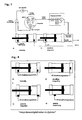
- the distance measuring device has a resonator in the form of a cavity resonator 1, which is formed from a metallic housing 5, preferably from titanium or Kovar.
- a metallic housing which is preferably tapered, optionally a dielectric 7, for example in the form of a ceramic z. B. Al 2 O 3 or in the form of a fluidic material, preferably air or inert gas such as. B. noble gases or nitrogen.
- the ceramic can, as shown in Fig. 1, be inserted into the housing.
- dielectric 7 itself is metallized, for example gold-plated. This has the advantage that the function over temperature depends only on the temperature coefficient of the dielectric 7 and not on that of the metallic housing.
- a Substrate 9 e.g. B. also ceramic, as a carrier for the Coupling facial expressions, for example in the form of a coplanar slot coupling or one Microstrip line and the active components of the Evaluation electronics or in the form of High frequency electronics positioned. About these Arrangement becomes the electromagnetic wave coupled.
- This back can also be gold-plated be and carry the entire high-frequency electronics 11.
- the resonance frequency f r of a cylindrical H mnp resonator can be made from ⁇ , ⁇ , the nth zeros of the derivative of the Bessel function of the mth order, as well as the diameter D of the cavity and the length L of the Determine cavity resonator.
- the functional relationship between ⁇ (for r D) 2 and (D / L) 2 can be clearly represented in a so-called mode diagram according to FIG. 6. From this so-called mode diagram, it is also relatively easy to identify areas in which no other modes can propagate.
- Another mode selection can be made by isolating the resonator top surface from the cylinder jacket , which corresponds to an open resonator with H 0np modes. It has proven to be particularly advantageous that the cavity resonator is designed in such a way that the H 0np modes, preferably the H 011 modes, can be propagated as the wave type, since no wall currents flow over the edges between the cladding surface and the end face. According to the line of the H 011 mode according to FIG. 6, only a section is to be sought in the vicinity of which no characteristic curve of other modes occurs, so that no other mode is excited even with certain fluctuations in the mechanical resonator dimensions and when tuning the frequency.
- the back of the cavity is provided with a substrate 9, preferably ceramic.
- the outer surface of the substrate 9 is preferred gilded.
- Only the coupling slots are left out 13 and 15 in the cavity resonator 1.
- the size of the Coupling slots 13 and 15 depends on the Dimensions of the dielectric 7. With a diameter the dielectric 7 of z. B. 6 mm is the size 0.3 mm by 0.2 mm.
- the electromagnetic wave itself is connected to the via a coplanar 50 ⁇ line Slit brought up and over a bond wire 17, for. B. 17.5 ⁇ m gold wire 17 is coupled into the slot 13.
- the bond wire is 17 on the opposite side with a Line structure, which is isolated, completed become.
- the cavity resonator 1 in both transmission and reflection modes operate. If the cavity resonator 1 in Transmission mode operated, then the electromagnetic wave at a second coupling slot 15 with the coplanar extension or Coupling uncoupled. This is in reflection mode Output terminated with 50 ⁇ .
- Dielectric 7 can with smaller diameters of Dielectric 7 advantageously also a microstrip line coupling be used.
- Oscillator 19 for example a voltage controlled oscillator (VCO), a detection diode 21 and a Frequency divider 23 is provided, which with a Evaluation electronics are connected.
- VCO voltage controlled oscillator
- a detection diode 21 and a Frequency divider 23 is provided, which with a Evaluation electronics are connected.
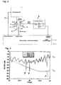
- FIG. 3 is an overall diagram or a Block diagram of how an advantageous one works Design of the application Distance measuring device shown.
- Control and evaluation electronics is via a Ramp control controlled a ramp generator, whereby the frequency of the transmission branch I tuned becomes.
- a via branch II resonance detector connected to the detector diode for example consisting of a two-stage Differentiators and a comparator on the second Derivation continuously monitors whether one from the Received branch II tapped video signal Indicates resonance.
- the resonance is recognizable that it is from a non-resonance in a high Steepness in a video signal of the receiving branch increasing oscillator frequency (see Fig. 4).
- the resonance becomes an integrator which ramp control controls stopped.
- the so set voltage is kept stable, with the divided down by the frequency divider 23 Oscillator frequency from a digital counter in the Evaluation electronics is determined.
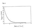
- the resonance frequency in the Cavity measured. Since the resonance frequency in Cavity from the distance of the object is dependent (see Fig. 5), can be determined by determining the The resonance frequency is directly related to the distance become. The new resonance frequency is thereby determines that the transmission frequency has changed will until the resonance frequency and transmission frequency to match. At this point, Detector diode detected a drop in performance. In parallel, the transmission frequency at the divider output of the frequency divider 23 determined. The measurement accuracy the distance to the object depends on how fast and with what accuracy determines the transmission frequency becomes. Determining the distance with a Measuring accuracy of 1 ⁇ m typically requires a distance of 0.5 mm an accuracy in the Frequency determination of at least 0.5 MHz at 26GHz.
- the Reflection and transmission characteristics which as a function of the resonance frequency at different Distances to the object is shown clearly Signal dips that occur when the resonance frequency is reached occur at a specified distance from the object. Moreover is a clear match of the signal dips between reflection and transmission characteristics recognition.
- the piezoelectric ceramic is a pressure, a force or a mass, it changes its mass accordingly Dielectric constant.
- the change in Dielectric constant shifts the Resonance frequency of the cavity resonator.
- the divided oscillator frequency not directly as Result size serves, but in a frequency and Phase control loop of a so-called phase-locked loop (PLL) is used.
- the Target frequency via a direct digital synthesizer (DDS) set to a frequency that is set as Reference variable enters the control loop. Fulfills that video signal recorded by the reception branch II Resonance condition, is in one in the Evaluation electronics already contain microcontrollers the resonance frequency and thus the distance to the target known.
- DDS direct digital synthesizer
- the following is intended to illustrate some areas of application the possible uses of the registration Distance measuring device based on a high-frequency proximity sensor being represented.
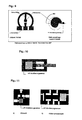
- a possible sensor arrangement for querying the position a rotary drive with the high-frequency proximity sensor is in for a rotary drive Figure 9 shown. Because such a high-frequency proximity switch builds extremely flat, can several switching points and several positions with the Sensor element can be realized, the setting for example via potentiometers or a teach-in Logic can be done.
- FIG. 10 is the schematic structure of a Shock absorber with integrated high-frequency proximity sensor shown.
- the principle of the invention can be also on valves with moving mechanical parts Apply (see Fig. 11), whereby by changing the position of the mechanical part the valve flow options be managed.
- Previous position queries were in pneumatics by magnetic field sensitive sensors realized that on the permanent magnet on the The piston or tappet of the valve react. It showed but it turns out that only for inexpensive solutions discrete position ranges through the fixed assembled and on the positions to be recorded adjusted sensor can be detected.
- Hydraulics is a magnetic query because of that Usually used ferromagnetic materials only possible to a limited extent.
- Fig. 12 there are different pressure measurements, i. H. Absolute pressure or relative or differential pressure measurement options shown.
- Absolute pressure or relative or differential pressure measurement options shown.
- this particular Application example becomes the pressure determination achieved that one on the RF proximity sensor membrane moving towards or away is detected at a distance becomes.
- DMS piezoresistive Strain Gauges
- the device according to the application has the advantage that the sensitive electronics outside the pressure measuring cell located.
- the measurement of the physical size distance by the Material property pressure dependent Dielectric constant replaced.
- the dielectric filled cavity resonator on the open Side preferably with a piezoelectric ceramic completed (see Fig. 13).
- the piezoelectric ceramic is fixed on the at the registration Spacer used sensor mounted. It then results when the sensor is switched on a fixed resonance frequency.
- the Piezoelectric ceramic on the sensor facing away from the sensor Side with pressure P within a pressure measuring cell and applied with a force then changes the dielectric constant of the piezoelectric Ceramics. This change means that the Resonance frequency shifts.
- the evaluation of this Frequency change and thus the conversion into corresponding pressure change preferably takes place after the method described for Figure 3 and Figure 7.
- the entire cavity of the resonator can also this application example with piezoelectric ceramics be filled (see Fig. 13b).
- the Movement of the measuring tip, which is caused by an object on the HF proximity sensor is moved towards or away measured. Because of the registration Distance measuring device can thus also take measurements in the Micrometer range can be performed.
- FIG. 15 relates, for example, to a level sensor.
- Figs. 15a, b, c are different installation locations of the High-frequency proximity sensor shown.
- the 15c becomes the high-frequency proximity sensor external to monitor for one corresponding level of the maximum level used. This is advantageously the Monitoring a maximum level or one predetermined set detection range guaranteed, when falling below the maximum Level or leak outside the set detection range a switching signal is shown.
- the high-frequency proximity switch used externally as a level switch can be used via the corresponding switching function the over or Below a specified fill level is displayed become.
- This external arrangement allows for one complex integration efforts can be dispensed with.
- the 14c can be adapted to existing systems Service units with HF transparent shells are used become.
- the Distance measuring device according to the application in addition to the above application areas used everywhere there can be where a distance measuring device into the Micrometer range is required.
Description
Claims (25)
- Abstandsmeßvorrichtung mit einem Sensor und einer Auswertelektronik,
dadurch gekennzeichnet, daß
der Sensor einen Resonator in Form eines Hohlraumresonators mit Resonatorgehäuse aufweist, wobei der Resonator eine koplanare Schlitzkopplung mit Einkopplungsleitung aufweist und die Einkopplungsleitung an dem Resonatorgehäuse abgeschlossen ist. - Abstandsmeßvorrichtung mit einem Sensor und einer Auswertelektronik, dadurch gekennzeichnet, daß der Sensor einen Resonator in Form eines Hohlraumresonators mit Resonatorgehäuse aufweist, wobei der Resonator eine Mikrostreifenleitung zur Einkopplung aufweist, wobei die Mikrostreifenleitung an dem Resonatorgehäuse abgeschlossen ist.
- Abstandsmeßvorrichtung nach Anspruch 1 oder 2, dadurch gekennzeichnet, daß der Resonator einen Hochfrequenzresonator aufweist, dessen Resonanzfrequenz je nach Abstand zu einem Objekt zwischen 1 und 100 GHz, vorzugsweise zwischen 20 und 30 GHz, insbesondere zwischen 22 und 26 GHz liegt.
- Abstandsmeßvorrichtung nach einem der Ansprüche 1 bis 3, dadurch gekennzeichnet, daß der Hohlraumresonator eine zylindrische Form aufweist, dessen zum Objekt zeigende Grundfläche offen, d. h. nichtmetallisiert ist.
- Abstandsmeßeinrichtung nach Anspruch 4, dadurch gekennzeichnet, daß der Hohlraumresonator mit einem fluidischen Material, vorzugsweise Luft oder einem inertem Gas, gefüllt ist.
- Abstandsmeßeinrichtung nach Anspruch 4, dadurch gekennzeichnet, daß der Hohlraumresonator mit einem Dielektrikum, vorzugsweise Al2O3 gefüllt ist.
- Abstandsmeßeinrichtung nach Anspruch 6, dadurch gekennzeichnet, daß der Hohlraumresonator eine offene Seite aufweist, die mit einer dünnen Scheibe eines Materials, vorzugsweise einer piezoelektrischen Keramik, abgeschlossen wird und dieses Material die Eigenschaften aufweist, durch entsprechende Belastung mit Druck, einer Kraft oder Masse ihre Dielektrizitätskonstante zu ändern.
- Abstandsmeßeinrichtung nach Anspruch 6, dadurch gekennzeichnet, daß der Hohlraumresonator mit dielektrischem Material, vorzugsweise piezoelektrischer Keramik gefüllt wird und das dielektrische Material die Eigenschaft aufweist, durch entsprechende Belastung mit Druck, einer Kraft oder Masse die Dielektrizitätskonstante zu ändern.
- Abstandsmeßeinrichtung nach einem der Ansprüche 6 oder 7, dadurch gekennzeichnet, daß die Oberfläche des Dielektrikums, mit Ausnahme der zum Objekt zeigenden Grundfläche mit einer dünnen Goldschicht überzogen ist, vorzugsweise aufgesputtert ist.
- Abstandsmeßeinrichtung nach einem der Ansprüche 6, 7 oder 8, dadurch gekennzeichnet, daß das Dielektrikum in ein metallisches Gehäuse, vorzugsweise aus Kovar oder Titan bestehend, eingeschoben wird.
- Abstandsmeßvorrichtung nach einem der Ansprüche 1 bis 10, dadurch gekennzeichnet, daß die Schlitzkopplung auf der dem Objekt abgewandten Seite des Resonators vorgesehen ist.
- Abstandsmeßeinrichtung nach Anspruch 11, dadurch gekennzeichnet, daß die koplanare Schlitzkopplung aus je einem Koppelschlitz für Sender und Empfänger besteht (Transmissionsmode), die kreisförmig angeordnet sind.
- Abstandsmeßeinrichtung nach Anspruch 11, dadurch gekennzeichnet, daß die koplanare Schlitzkopplung aus einem Koppelschlitz für Sender und Empfänger besteht (Reflektionsmode).
- Abstandsmeßvorrichtung nach einem der Ansprüche 1 bis 13, dadurch gekennzeichnet, daß die Einkopplung und der Resonator als Wellentyp die H0np-Moden, vorzugsweise die H011-Mode, zuläßt.
- Abstandsmeßvorrichtung nach einem der Ansprüche 1 bis 14, dadurch gekennzeichnet, daß der Sensor eine Hochfrequenz-Elektronik mit einem Sende- und Empfangszweig aufweist.
- Abstandsmeßvorrichtung nach Anspruch 15, dadurch gekennzeichnet, daß der Sendezweig aus einem Oszillator, vorzugsweise einem Voltage Controlled Oszillator (VCO), besteht.
- Abstandsmeßvorrichtung nach Anspruch 15, dadurch gekennzeichnet, daß der Empfangszweig aus mindestens einer Hochfrequenz-Diode besteht.
- Abstandsmeßvorrichtung nach Anspruch 16, dadurch gekennzeichnet, daß die Oszillatorfrequenz über eine geschlossene Regelschleife einer Sollfrequenz (Führungsgröße) folgt.
- Abstandsmeßvorrichtung nach Anspruch 18, dadurch gekennzeichnet, daß die Regelschleife (PLL: Phase Locked Loop) aus mindestens einem Frequenzteiler, einem Phasendiskriminator und einem Tielpaßfilter besteht und die Sollfrequenz über einen DDS (Direct Digital Synthesizer) vorgegeben wird (dynamische Frequenzregelung bzw. -bestimmung).
- Abstandsmeßvorrichtung nach Anspruch 18, dadurch gekennzeichnet, daß die Regelschleife aus mindestens einem Frequenzteiler besteht und vorzugsweise über einen Frequenzzähler, Mikrocontroller und Digital-Analogwandler geschlossen wird (statische Frequenzregelung bzw. - bestimmung).
- Verfahren zur Bestimmung eines Abstands eines Objekts zu einer Abstandsmeßvorrichtung gemäß einem der Ansprüche 1 bis 20, welches die Schritte aufweist:a) Bereitstellen des Hohlraumresonators;b) Bestimmung der Resonanzfrequenz, um den Abstand zum Objekt zu ermitteln.
- Verfahren nach Anspruch 21, dadurch gekennzeichnet, daß die Bestimmung der Resonanzfrequenz so erfolgt, daß ein im Sendezweig vorgesehener Oszillator solange in seiner Sendefrequenz verstimmt wird, bis im Empfangszweig ein Leistungseinbruch bei einer Resonanz festgestellt ist.
- Verfahren nach Anspruch 22, dadurch gekennzeichnet, daß die Sendefrequenz des Oszillators durch eine Rampensteuerung und einen Rampengenerator verstimmt wird.
- Verfahren nach Anspruch 22, dadurch gekennzeichnet, daß die Sendefrequenz des Oszillators über einen direkten digitalen Sythesizer (DDS) eingestellt wird.
- Verfahren nach Anspruch 21, dadurch gekennzeichnet, daß alternativ zu Schritt b) eine Bestimmung der Resonanzfrequenz erfolgt, um bei Abstand Null zum Objekt den Druck, die Kraft oder Masse auf das Objekt zu ermitteln.
Applications Claiming Priority (5)
| Application Number | Priority Date | Filing Date | Title |
|---|---|---|---|
| DE19733109 | 1997-07-31 | ||
| DE19733109 | 1997-07-31 | ||
| DE19807593A DE19807593A1 (de) | 1997-07-31 | 1998-02-23 | Abstandsmeßvorrichtung und Verfahren zur Bestimmung eines Abstands |
| DE19807593 | 1998-02-23 | ||
| PCT/EP1998/004815 WO1999006788A2 (de) | 1997-07-31 | 1998-07-31 | Abstandsmessvorrichtung und verfahren zur bestimmung eines abstands |
Publications (2)
| Publication Number | Publication Date |
|---|---|
| EP1000314A2 EP1000314A2 (de) | 2000-05-17 |
| EP1000314B1 true EP1000314B1 (de) | 2002-04-10 |
Family
ID=26038741
Family Applications (1)
| Application Number | Title | Priority Date | Filing Date |
|---|---|---|---|
| EP98945135A Expired - Lifetime EP1000314B1 (de) | 1997-07-31 | 1998-07-31 | Abstandsbestimmung mit einem offenen Hohlraumresonator |
Country Status (5)
| Country | Link |
|---|---|
| US (1) | US6445191B1 (de) |
| EP (1) | EP1000314B1 (de) |
| JP (1) | JP2001512229A (de) |
| ES (1) | ES2177050T3 (de) |
| WO (1) | WO1999006788A2 (de) |
Cited By (7)
| Publication number | Priority date | Publication date | Assignee | Title |
|---|---|---|---|---|
| EP1933132A2 (de) | 2006-12-15 | 2008-06-18 | Voith Patent GmbH | Verfahren und Vorrichtung zur Bestimmung der Feuchte einer laufenden Materialbahn |
| EP2031417A1 (de) | 2007-08-30 | 2009-03-04 | Balluff GmbH | Mikrowellen-Näherungssensor und Verfahren zur Bestimmung des Abstands zwischen einem Zielobjekt und einem Messkopf eines Mikrowellen-Näherungssensors |
| DE102007042954A1 (de) | 2007-08-30 | 2009-03-05 | Balluff Gmbh | Mikrowellen-Näherungssensor und Verfahren zur Ermittlung des Abstands zwischen einem Messkopf und einem Zielobjekt |
| WO2015000452A1 (de) | 2013-07-01 | 2015-01-08 | Balluff Gmbh | Näherungssensor und verfahren zur messung des abstands eines objekts |
| DE102014007643A1 (de) | 2014-05-23 | 2015-11-26 | Astyx Gmbh | Abstandmessvorrichtung, insbesondere für metallische und dielektrische Zielobjekte |
| WO2016101940A1 (de) | 2014-12-23 | 2016-06-30 | Balluff Gmbh | Näherungssensor und verfahren zur messung des abstands eines targets |
| WO2016141905A1 (de) | 2015-03-06 | 2016-09-15 | Balluff Gmbh | Näherungssensor und verfahren zur messung des abstands eines targets |
Families Citing this family (15)
| Publication number | Priority date | Publication date | Assignee | Title |
|---|---|---|---|---|
| DE19807593A1 (de) * | 1997-07-31 | 1999-02-04 | Mikrowellen Technologie Und Se | Abstandsmeßvorrichtung und Verfahren zur Bestimmung eines Abstands |
| DE10205904A1 (de) * | 2002-02-13 | 2003-08-21 | Mikrowellen Technologie Und Se | Abstandsmessvorrichtung und Verfahren zur Bestimmung eines Abstands |
| DE10225246A1 (de) * | 2002-06-07 | 2004-01-08 | Festo Ag & Co. | Kontraktionseinheit mit Positionssensoreinrichtung |
| US20040227524A1 (en) * | 2003-05-12 | 2004-11-18 | Boris Kesil | Method and system for measuring thickness of thin films with automatic stabilization of measurement accuracy |
| US6989675B2 (en) * | 2003-03-13 | 2006-01-24 | Multimetrixs Llc | Method and apparatus for precision measurement of film thickness |
| DE102005008880A1 (de) * | 2004-09-09 | 2006-07-13 | Mts Mikrowellen-Technologie Und Sensoren Gmbh | Mikrowellensensor zur hochgenauen Niveaumessung in einer Luftfeder |
| US7092840B2 (en) * | 2004-02-26 | 2006-08-15 | Honeywell International, Inc. | High temperature resonant transmission line sensor and methods |
| US20080092638A1 (en) * | 2006-10-19 | 2008-04-24 | Bayer Healthcare Llc | Wireless analyte monitoring system |
| US8244494B2 (en) * | 2007-04-06 | 2012-08-14 | Hypertherm, Inc. | Plasma insensitive height sensing |
| US8373425B2 (en) * | 2007-04-06 | 2013-02-12 | Hypertherm, Inc. | Plasma insensitive height sensing |
| US7888950B2 (en) * | 2007-07-06 | 2011-02-15 | Honeywell International Inc. | Structural health monitoring sensor system and method using resonant transmission line sensors |
| WO2009021755A2 (de) * | 2007-08-16 | 2009-02-19 | Astyx Gmbh | Doppelkolbenstange |
| US8085156B2 (en) * | 2009-04-08 | 2011-12-27 | Rosemount Inc. | RF cavity-based process fluid sensor |
| RU2497027C1 (ru) * | 2012-10-31 | 2013-10-27 | Открытое акционерное общество "Центральный научно-исследовательский институт автоматики и гидравлики" (ОАО "ЦНИИАГ") | Гидропривод дискретного углового хода |
| JP2022178665A (ja) * | 2021-05-20 | 2022-12-02 | 富士フイルムビジネスイノベーション株式会社 | 測定装置、及び画像形成装置 |
Family Cites Families (23)
| Publication number | Priority date | Publication date | Assignee | Title |
|---|---|---|---|---|
| US3522527A (en) | 1967-09-13 | 1970-08-04 | British Iron Steel Research | Method and apparatus for measuring material thickness |
| US3628136A (en) | 1969-09-05 | 1971-12-14 | Garrett Corp | Means for measuring clearances in a gas turbine including a coaxial cable capacitor |
| GB1331525A (en) * | 1971-08-19 | 1973-09-26 | Dn Znamei G Stvenny Uni Im 300 | Method and apparatus for gauging the thickness of flat metal products |
| US4211987A (en) | 1977-11-30 | 1980-07-08 | Harris Corporation | Cavity excitation utilizing microstrip, strip, or slot line |
| NL8102527A (nl) | 1981-05-22 | 1982-12-16 | Philips Nv | Kleurenbeeldbuis. |
| SU1103098A1 (ru) | 1982-08-24 | 1984-07-15 | Предприятие П/Я А-1209 | Частотный датчик давлени |
| JPS5988673A (ja) * | 1982-11-12 | 1984-05-22 | Hitachi Ltd | レ−ザ測距装置 |
| JPS59169212A (ja) * | 1983-03-16 | 1984-09-25 | Nec Corp | マイクロ波発振装置 |
| JPS6183946A (ja) * | 1984-10-01 | 1986-04-28 | Kanzaki Paper Mfg Co Ltd | シ−ト状物質の配向測定方法 |
| JPS63145951A (ja) * | 1986-12-09 | 1988-06-18 | Daipoole:Kk | 糸状材料の物性量測定装置 |
| US4845422A (en) * | 1986-12-24 | 1989-07-04 | General Electric Company | Microwave proximity sensor |
| ATE75034T1 (de) * | 1987-11-27 | 1992-05-15 | Schmall Karl Heinz | Verwendung eines dielektrischen mikrowellenresonators und sensorschaltung. |
| JPH01163645A (ja) | 1987-12-21 | 1989-06-27 | Kanzaki Paper Mfg Co Ltd | シート状材料の高周波特性測定装置 |
| NL8902628A (nl) | 1989-10-24 | 1991-05-16 | Hollandse Signaalapparaten Bv | Fm-cw radarapparaat. |
| DE4040084C2 (de) | 1990-12-14 | 1998-09-24 | Dittel Walter Luftfahrt | Berührungsloses Abstandsmeßgerät |
| WO1993006468A1 (en) | 1991-09-20 | 1993-04-01 | Dipole Electronics Co. Ltd. | Equipment for measuring physical quantity |
| US5325095A (en) | 1992-07-14 | 1994-06-28 | The United States Of America As Represented By The United States Department Of Energy | Stepped frequency ground penetrating radar |
| JP2746061B2 (ja) | 1993-07-09 | 1998-04-28 | 日本電気株式会社 | 音声パケット交換装置 |
| FR2718249B1 (fr) | 1994-04-05 | 1996-04-26 | Thomson Csf | Procédé et dispositif radar de mesure de distance. |
| JPH08222951A (ja) * | 1995-02-20 | 1996-08-30 | Fujitsu General Ltd | 局部発振回路 |
| US5596325A (en) | 1995-07-07 | 1997-01-21 | Nonlinear Technologies, Inc. | FM-CW radar transceiver |
| DE19543179A1 (de) | 1995-11-20 | 1997-05-22 | Forschungszentrum Juelich Gmbh | Mikrowellenresonator, Verfahren zur Herstellung eines solchen Resonators sowie Verfahren zur Kompensation des Temperaturkoeffizienten der Resonanzfrequenz eines Mikrowellenresonators |
| DE19833220A1 (de) | 1997-12-15 | 1999-06-17 | Mikrowellen Technologie Und Se | Abstandsmeßvorrichtung und Verfahren zur Bestimmung eines Abstandes |
-
1998
- 1998-07-31 WO PCT/EP1998/004815 patent/WO1999006788A2/de active IP Right Grant
- 1998-07-31 EP EP98945135A patent/EP1000314B1/de not_active Expired - Lifetime
- 1998-07-31 JP JP2000505477A patent/JP2001512229A/ja active Pending
- 1998-07-31 ES ES98945135T patent/ES2177050T3/es not_active Expired - Lifetime
- 1998-07-31 US US09/463,806 patent/US6445191B1/en not_active Expired - Lifetime
Non-Patent Citations (2)
| Title |
|---|
| Seite 645 aus dem Buch 'Principles and Practice of Radar' by H.E.Penrose, George Newness Ltd, London (GB), 1949 * |
| Seiten 467 und 468 aus dem Buch 'Taschenbuch der Hochfrequenztechnik' herausgegeben von H.Meinke und F.W.Gundlach, Springer Verlag, Berlin (DE) 1962 * |
Cited By (14)
| Publication number | Priority date | Publication date | Assignee | Title |
|---|---|---|---|---|
| EP1933132A2 (de) | 2006-12-15 | 2008-06-18 | Voith Patent GmbH | Verfahren und Vorrichtung zur Bestimmung der Feuchte einer laufenden Materialbahn |
| EP2031417A1 (de) | 2007-08-30 | 2009-03-04 | Balluff GmbH | Mikrowellen-Näherungssensor und Verfahren zur Bestimmung des Abstands zwischen einem Zielobjekt und einem Messkopf eines Mikrowellen-Näherungssensors |
| DE102007042954A1 (de) | 2007-08-30 | 2009-03-05 | Balluff Gmbh | Mikrowellen-Näherungssensor und Verfahren zur Ermittlung des Abstands zwischen einem Messkopf und einem Zielobjekt |
| DE102007042955A1 (de) | 2007-08-30 | 2009-03-05 | Balluff Gmbh | Mikrowellen-Näherungssensor und Verfahren zur Bestimmung des Abstands zwischen einem Zielobjekt und einem Messkopf eines Mikrowellen-Näherungssensors |
| US10132922B2 (en) | 2013-07-01 | 2018-11-20 | Balluff Gmbh | Proximity sensor and method for measuring the distance from an object |
| WO2015000452A1 (de) | 2013-07-01 | 2015-01-08 | Balluff Gmbh | Näherungssensor und verfahren zur messung des abstands eines objekts |
| DE102014007643A1 (de) | 2014-05-23 | 2015-11-26 | Astyx Gmbh | Abstandmessvorrichtung, insbesondere für metallische und dielektrische Zielobjekte |
| WO2015176822A1 (de) | 2014-05-23 | 2015-11-26 | Astyx Gmbh | Abstandsmessvorrichtung, insbesondere für metallische und dielektrische zielobjekte |
| US11635285B2 (en) | 2014-05-23 | 2023-04-25 | Cruise Munich Gmbh | Distance measuring device, in particular for dielectric and metallic target objects |
| WO2016101940A1 (de) | 2014-12-23 | 2016-06-30 | Balluff Gmbh | Näherungssensor und verfahren zur messung des abstands eines targets |
| US10598777B2 (en) | 2014-12-23 | 2020-03-24 | Balluff Gmbh | Proximity sensor and method for measuring the distance from a target |
| DE112014007276B4 (de) | 2014-12-23 | 2021-11-11 | Balluff Gmbh | Näherungssensor und Verfahren zur Messung des Abstands eines Targets |
| WO2016141905A1 (de) | 2015-03-06 | 2016-09-15 | Balluff Gmbh | Näherungssensor und verfahren zur messung des abstands eines targets |
| US10534077B2 (en) | 2015-03-06 | 2020-01-14 | Balluff Gmbh | Proximity sensor and method for measuring the distance from an object |
Also Published As
| Publication number | Publication date |
|---|---|
| EP1000314A2 (de) | 2000-05-17 |
| US6445191B1 (en) | 2002-09-03 |
| WO1999006788A3 (de) | 1999-04-08 |
| ES2177050T3 (es) | 2002-12-01 |
| JP2001512229A (ja) | 2001-08-21 |
| WO1999006788A2 (de) | 1999-02-11 |
Similar Documents
| Publication | Publication Date | Title |
|---|---|---|
| EP1000314B1 (de) | Abstandsbestimmung mit einem offenen Hohlraumresonator | |
| DE102006052637B4 (de) | Vorrichtung und Verfahren zur Bestimmung zumindest eines Parameters eines Mediums | |
| DE19903183A1 (de) | Hochfrequenz-Abstandsmeßeinrichtung | |
| EP1040316B1 (de) | Abstandsmessvorrichtung und verfahren zur bestimmung eines abstandes | |
| DE19833220A1 (de) | Abstandsmeßvorrichtung und Verfahren zur Bestimmung eines Abstandes | |
| DE19807593A1 (de) | Abstandsmeßvorrichtung und Verfahren zur Bestimmung eines Abstands | |
| WO2008131957A1 (de) | Abstandsmessvorrichtung und verfahren zur bestimmung eines abstands und ein geeigneter reflexionskörper | |
| DE3438332C2 (de) | ||
| WO2003069269A2 (de) | Abstandsmessvorrichtung und verfahren zur bestimmung eines abstands | |
| EP2656435A1 (de) | Abstimmbares hochfrequenzfilter | |
| EP2054633B1 (de) | Verfahren und vorrichtung zum bestimmen der position eines kolbens in einem zylinder | |
| DE102012020979A1 (de) | Abstimmbares Hochfrequenzfilter | |
| US20100073111A1 (en) | Tem mode resonator | |
| WO2015000452A1 (de) | Näherungssensor und verfahren zur messung des abstands eines objekts | |
| EP0320442B1 (de) | Verwendung eines dielektrischen Mikrowellen-Resonators und Sensorschaltung | |
| EP2002282B1 (de) | Mikrowellen-positionsmessvorrichtung und positionsmessverfahren | |
| EP1112603A1 (de) | Abstimmbarer hohlraumresonator | |
| DE4411815A1 (de) | Verfahren zur Messung eines mehrkomponentigen und/oder mehrphasigen strömenden Mediums | |
| US20110001585A1 (en) | tuneable filter and a method of tuning such a filter | |
| DE4217736C2 (de) | Einrichtung zur Überwachung eines Auftrags auf ein Substrat | |
| EP2006549B1 (de) | Messvorrichtung zur Messung wenigstens eines Parameters in einem fluidischen Zylinder mit Hilfe von Mikrowellen | |
| EP1011166A1 (de) | Mikrowellen-Koppelelement | |
| EP2016292A1 (de) | Mikrowellen-positionsmessvorrichtung und positionsmessverfahren | |
| EP3076030A1 (de) | Positionsmesssystem | |
| DE202013012904U1 (de) | Näherungssensor |
Legal Events
| Date | Code | Title | Description |
|---|---|---|---|
| PUAI | Public reference made under article 153(3) epc to a published international application that has entered the european phase |
Free format text: ORIGINAL CODE: 0009012 |
|
| 17P | Request for examination filed |
Effective date: 20000131 |
|
| AK | Designated contracting states |
Kind code of ref document: A2 Designated state(s): DE ES FR GB IT |
|
| GRAG | Despatch of communication of intention to grant |
Free format text: ORIGINAL CODE: EPIDOS AGRA |
|
| RIC1 | Information provided on ipc code assigned before grant |
Free format text: 7G 01B 1/00 A, 7G 01B 15/00 B |
|
| RTI1 | Title (correction) |
Free format text: DISTANCE DETERMINATION WITH AN OPEN CAVITY RESONATOR |
|
| 17Q | First examination report despatched |
Effective date: 20010405 |
|
| RIN1 | Information on inventor provided before grant (corrected) |
Inventor name: DR.JOSEF WENGER Inventor name: TRUMMER, GUENTHER |
|
| GRAG | Despatch of communication of intention to grant |
Free format text: ORIGINAL CODE: EPIDOS AGRA |
|
| GRAH | Despatch of communication of intention to grant a patent |
Free format text: ORIGINAL CODE: EPIDOS IGRA |
|
| REG | Reference to a national code |
Ref country code: GB Ref legal event code: IF02 |
|
| GRAH | Despatch of communication of intention to grant a patent |
Free format text: ORIGINAL CODE: EPIDOS IGRA |
|
| GRAA | (expected) grant |
Free format text: ORIGINAL CODE: 0009210 |
|
| AK | Designated contracting states |
Kind code of ref document: B1 Designated state(s): DE ES FR GB IT |
|
| RIN1 | Information on inventor provided before grant (corrected) |
Inventor name: DR.JOSEF WENGER Inventor name: TRUMMER, GUENTHER |
|
| REF | Corresponds to: |
Ref document number: 59803757 Country of ref document: DE Date of ref document: 20020516 |
|
| ET | Fr: translation filed | ||
| GBT | Gb: translation of ep patent filed (gb section 77(6)(a)/1977) |
Effective date: 20020913 |
|
| REG | Reference to a national code |
Ref country code: ES Ref legal event code: FG2A Ref document number: 2177050 Country of ref document: ES Kind code of ref document: T3 |
|
| PLBE | No opposition filed within time limit |
Free format text: ORIGINAL CODE: 0009261 |
|
| STAA | Information on the status of an ep patent application or granted ep patent |
Free format text: STATUS: NO OPPOSITION FILED WITHIN TIME LIMIT |
|
| 26N | No opposition filed |
Effective date: 20030113 |
|
| REG | Reference to a national code |
Ref country code: FR Ref legal event code: CD Ref country code: FR Ref legal event code: CA |
|
| REG | Reference to a national code |
Ref country code: ES Ref legal event code: PC2A |
|
| REG | Reference to a national code |
Ref country code: DE Ref legal event code: R082 Ref document number: 59803757 Country of ref document: DE Representative=s name: KUNZ, HERBERT, DIPL.-PHYS. DR.RER.NAT., DE Ref country code: DE Ref legal event code: R082 Ref document number: 59803757 Country of ref document: DE Representative=s name: DR. KUNZ & KOLLEGEN PATENTANWALTSKANZLEI, DE |
|
| REG | Reference to a national code |
Ref country code: DE Ref legal event code: R082 Ref document number: 59803757 Country of ref document: DE Representative=s name: KUNZ, HERBERT, DIPL.-PHYS. DR.RER.NAT., DE |
|
| REG | Reference to a national code |
Ref country code: DE Ref legal event code: R082 Ref document number: 59803757 Country of ref document: DE Representative=s name: KUNZ, HERBERT, DIPL.-PHYS. DR.RER.NAT., DE |
|
| REG | Reference to a national code |
Ref country code: DE Ref legal event code: R082 Ref document number: 59803757 Country of ref document: DE Representative=s name: KUNZ, HERBERT, DIPL.-PHYS. DR.RER.NAT., DE |
|
| REG | Reference to a national code |
Ref country code: FR Ref legal event code: PLFP Year of fee payment: 19 |
|
| REG | Reference to a national code |
Ref country code: FR Ref legal event code: PLFP Year of fee payment: 20 |
|
| PGFP | Annual fee paid to national office [announced via postgrant information from national office to epo] |
Ref country code: GB Payment date: 20170719 Year of fee payment: 20 Ref country code: ES Payment date: 20170825 Year of fee payment: 20 Ref country code: FR Payment date: 20170724 Year of fee payment: 20 Ref country code: IT Payment date: 20170728 Year of fee payment: 20 Ref country code: DE Payment date: 20170724 Year of fee payment: 20 |
|
| REG | Reference to a national code |
Ref country code: DE Ref legal event code: R071 Ref document number: 59803757 Country of ref document: DE |
|
| REG | Reference to a national code |
Ref country code: GB Ref legal event code: PE20 Expiry date: 20180730 |
|
| PG25 | Lapsed in a contracting state [announced via postgrant information from national office to epo] |
Ref country code: GB Free format text: LAPSE BECAUSE OF EXPIRATION OF PROTECTION Effective date: 20180730 |
|
| REG | Reference to a national code |
Ref country code: ES Ref legal event code: FD2A Effective date: 20201106 |
|
| PG25 | Lapsed in a contracting state [announced via postgrant information from national office to epo] |
Ref country code: ES Free format text: LAPSE BECAUSE OF EXPIRATION OF PROTECTION Effective date: 20180801 |