Measurement of the refractive index can be used to characterize liquid and solid samples, for example to measure the concentration of solutions. Knowledge of the refractive index allows you to control the quality of multi-component mixtures and check samples for purity. This article will give you a broad overview of this fascinating topic.
Basics of refractometry
What is refractive index?
Every material with which light interacts has a refractive index (RI, symbolized as n). This constant, dimensionless number describes how fast light moves through a specific medium in relation to how fast it moves through a reference medium (usually vacuum or air). The lower the optical density of the medium, the higher the speed of light inside the medium and the lower its refractive index.
Examples of the speed of light in different media
| Vacuum | 299 792 km/s |
| Air | 299 710 km/s |
| Water | 225 000 km/s |
| Sapphire | 170 000 km/s |
The refractive index of a substance is dependent on the wavelength λ of the light and the temperature T of the substance. Reference to the refractive index must therefore also specify the wavelength and temperature, if the measurement is not done under standard conditions.
The standard wavelength for refractometric measurements is 589 nm. Under these conditions, the refractive index (n) is often written as nD or nD.
Several refractive index scales are in use.
The absolute refractive index of a medium is the ratio of the speed of light in vacuum relative to the speed in the medium.
While this is the most fundamental definition, it is more common to use the refractive index relative to air.
Since the (absolute) refractive index of the medium of interest as well as the refractive index of air depend on temperature, it is necessary to specify the details.
Common variants are:
- the temperature-dependent refractive index of the medium relative to standard air, that is air at 20 °C, 1013 hPa, and 50 % relative humidity
- the temperature-dependent refractive index of the medium relative to air of the same temperature
Examples of different refractive indices
(wavelength = 589.3 nm, temperature = 20.0 °C)
| Sample | nD(T=20 °C) relative to vacuum |
|---|---|
| Vacuum | 1.00000 |
| Air | 1.00027 |
| Water | 1.33335 |
| Dodecane | 1.42211 |
| Tetrachloroethylene | 1.50621 |
| Bromonaphtalene | 1.65829 |
| Sapphire Al2O3 | 1.76 |
| YAG | 1.83 |
| Diamond C | 2.42 |
Measuring principle of refractometers
The operation of the refractometer is based on the physical principle of light refraction – Snell’s law – which is further described in the next chapter. Light slows down as it passes into more optically dense media, and speeds up as it passes into less optically dense media. The change in speed is accompanied by a change in direction, and at a certain angle of incidence, the light does not refract in the second medium at all, but is entirely reflected. The angle at which this occurs is known as the critical angle, and it is this angle that the refractometer measures.
How to understand the critical angle
An easy way to visualize this phenomenon is in terms of the perceived and actual location of a fish below the surface of a body of water. The refraction of light leaving the water and entering the air causes us to perceive the location of the fish as closer than it actually is.
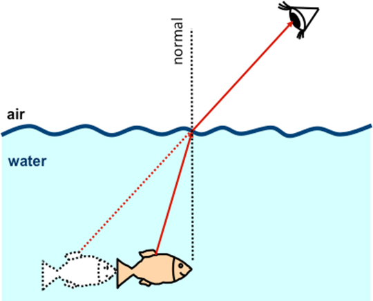
Figure 1: Refraction of the light reflected off the fish (from the sun) causes us to perceive the position of the fish as closer than it actually is.
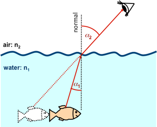
Figure 2: The larger the difference in refractive indices, the larger the change in direction
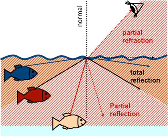
Figure 3: Refraction of light from fish at various positions. For the beige fish: one part of light is refracted into the air, the other part is reflected back into the water. For the red fish: refracted part is exactly in the boundary surface and does not go into the air. And for the blue fish: no light ray is refracted into the air. All light is reflected back into the water. This is total reflection.

Figure 4: Total reflection
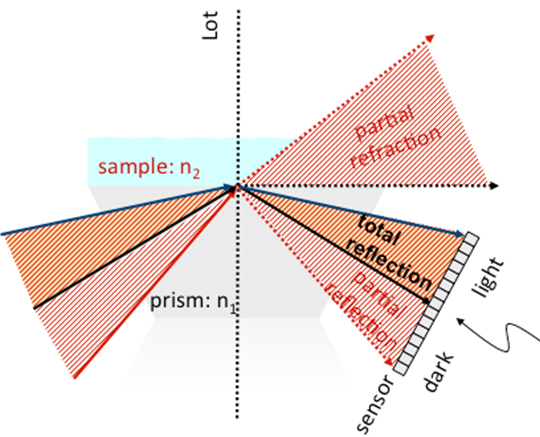
Figure 5: Applying this fish example to the refractometer: Instead of a lake, take prism (n1), and instead of air, take sample (n2).
Snell's law
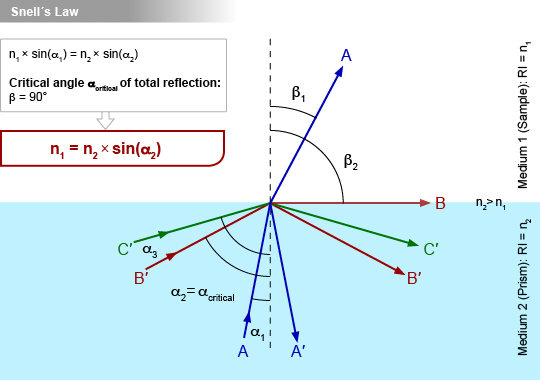
Figure 6: Incoming light rays are either totally reflected (α>αcritical) or partly refracted and partly reflected (α<αcritical), depending on their angle.
In this diagram, beam A strikes the interface of medium 1 (with refractive index = n1) and medium 2 (with refractive index = n2, where n2 > n1) at the incident angle α1. This results in the partial reflection (beam A’) and partial refraction (beam A at angle β1) at the boundary surface.
At a certain angle of incidence α2, one part of the light beam is reflected and another part is refracted exactly along the interface of the two media. This is known as total reflection and the angle is referred to as the critical angle of total reflection.
When the beam is incident at an angle greater then αcritical, the light beam will be entirely reflected (beam C’).
Snell’s law can be applied to determine the RI of medium 1. The law states that the ratio of the RIs is equal to the inverse ratio of the sinus of angles α1 and β1.
$$\frac{{n}_{1}}{{n}_{2}}=\frac{\sin{{\alpha}_{1}}}{\sin{{β}_{1}}}$$
When α2 = αcritical, the angle α1 = β1 = 90°. Substituting these values into Snell’s law gives
$${ n }_{ 1 }={ n }_{ 2 }\cdot \sin { { \alpha }_{ critical } } $$
Measuring the RI of medium 2 and the critical angle of total reflection αcritical can therefore yield the RI of medium 2.
Schematic setup of a refractometer
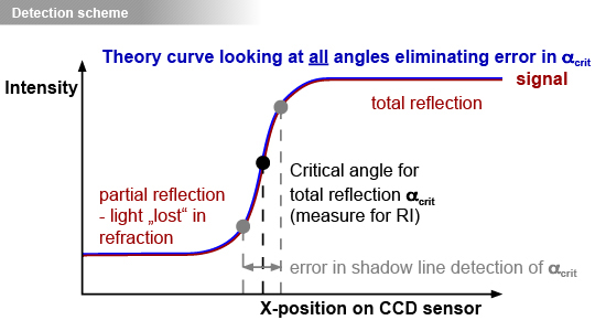
Figure 6: Diagram of CCD sensor critical angle detection. A theoretical curve is fitted to all collected data points and from this the critical angle αcritical can be determined precisely.
A refractometer consists of a light source, filtered to a single wavelength, which is directed towards the prism-sample interface by a converging lens. This creates a range of incidence angles, some of which (those less than the critical angle) will be completely reflected. A Charge-coupled Device (CCD) sensor precisely measures the intensity of the reflected light and determines the exact angle αcritical at which light begins to be completely reflected. Because this angle is dependent on the ratio of the refractive index of the prism to that of the sample, the refractive index of the sample can be determined using the known refractive index of the prism.
Figure 6 illustrates the resultant step in light intensity, as measured by the CCD sensor, which is used to determine the critical angle. A theoretical “Fresnel” curve is applied to the video signal taken with the CCD sensor, which allows for the objective determination of the critical angle. This technique guarantees a more accurate and reliable determination of the refraction index compared to simple shadow line detection.
Figure 7 shows a schematic setup of a refractometer. To learn more about the measuring principle of refractometers, watch this video:

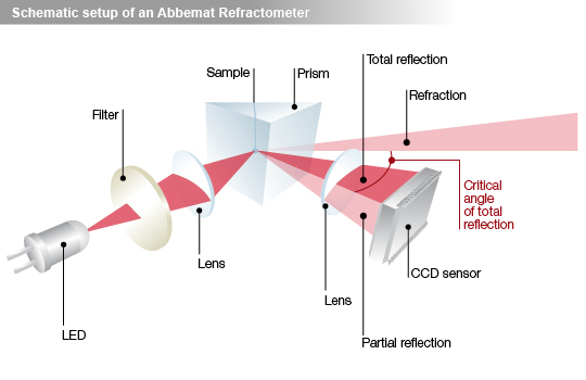
Figure 7: Schematic setup of a refractometer.
Sample to be measured is in direct contact with the measuring prism (Figure 7). The incoming light of angles less than the critical angle of total reflection is partly refracted through the sample, while incoming light of angles greater than the critical angle is totally reflected. A high-resolution sensor array measures the amount of this reflected light.
Factors which influence a refractive index result
Refractive index’s dependence on wavelength
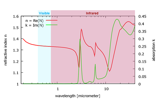
Figure 8: Dispersion curve of water
For almost all materials, the refractive index differs for different wavelengths, in a pattern characteristic to each material. This is known as the dispersion relation.
Figure 8 illustrates the absorption (blue curve) and dispersion relation (red curve) of water over a range of wavelengths. The refractive index drops through the visible spectrum into the beginning of the infrared, while nearly no absorption is seen in this range.
In order to accurately determine the refractive index of a sample, it is therefore necessary to ensure the precision of the wavelength with an interference filter. While most refractometric measurements are done at 589 (or 589.3) nm, the wavelength of the sodium D-line, some applications require other wavelengths.
The industry standard use of the 589 nm wavelength is a historical throwback to sodium lamps being widely available as a cheap and reliable light source. The name “D-line” refers to the symbol given to the spectral line of sodium by Joseph von Fraunhofer, the German physicist credited with the discovery and mapping of over 570 spectral lines.
Refractive index’s dependence on temperature
Temperature is another major influence on refractive index and must therefore be precisely controlled and measured during the entire procedure. While older instruments often employ a water bath for this purpose, newer instruments often have the option to use more precise Peltier temperature control. High-precision temperature control stabilizes the temperature of both the sample and the measuring prism, and is combined with highly accurate temperature sensors.
How refractometers provide highly accurate results by considering all relevant factors is summarized in this video:
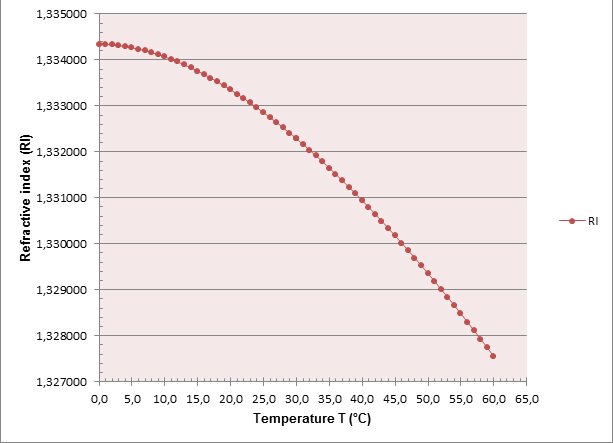
Figure 9: Refractive index (λ = 589.3nm) of water at temperature T relative to vacuum, calculated according to Tilton & Taylor (1938)
Applications & outlook
As shown in this article, refractive index determination is a simple and useful method for characterizing and measuring the concentration of substances. It is frequently used at research and industrial laboratories, both for quality control and product development. Applications include the investigation of pharmaceuticals, food analysis (including quality control of honey), the evaluation of scents and aromas, and the online monitoring of food, beverages, and pharmaceuticals.