Hierarchical Debug In Non-Equivalence Checking
HEIDI ZHENG
Manager at NanDigits, Functional Netlist ECO, Functional Safety Fault Verification
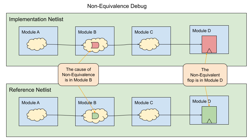
When a non-equivalence is found in one module, the origin of the root cause may actually reside in a different module, thanks to the propagation of combinational paths. In Figure 1, the non-equivalent flip-flop in Module D might be attributable to an issue in Module B. Employing the previously discussed method, the GUI-based debugging process can systematically guide the debugging efforts towards the precise point of failure. You can access the full article via the following link https://www.linkedin.com/pulse/counterexample-schematic-non-equivalence-debug-heidi-zheng/

Nonetheless, a module between, like Module C, might exhibit discrepancies in certain logic paths when comparing the Implementation Netlist with the Reference Netlist. To tackle this issue, a novel hierarchical signal comparison feature has been introduced.
For instance, in Figure 2, as we delve into a module, the circuit begins to display variations in its format in the two netlists. In such cases, extending the schematic to more levels could be beneficial for ongoing debugging efforts. But this new approach for verifying the logic values of boundary signals proves to be a more efficient method.

Running the 'Compare Hierarchical Fanin Endpoints' command allows for the comparison of boundary signals that interact with other hierarchical levels, both in terms of their names and logic values.

Following the execution of the command, the boundary signals encompass various types: input ports leading to the current module, output ports of its sub-modules, and the registers within the current module. These signal names are accompanied by their corresponding counter-example simulation logic values. In cases where a signal is identified as phase-inverted, an 'inv' string is appended to the end of the line.
If all the boundary signals exhibit identical names and logic values, it signifies that the origin of the non-equivalence issue lies within the current module. Conversely, when there are disparities in the logic values of these signals, the debugging process can advance from the point where the boundary signals diverge.

As depicted in Figure 4, two signals exhibit distinct logic values. These signals can be imported into the schematic for more in-depth examination. All GUI windows are interactive, allowing you to simply hover your cursor over the desired line and right-click to choose the "copy" command, facilitating the transfer of the signals in question to the schematic.

Following this action, Module C, which has been posing challenges during the debugging process, is effectively circumvented. Within the schematic, you can proceed to track the mismatched signals that were imported using the aforementioned method. These signals interface with Module C, although for the purpose of the debugging process, Module C can be considered equivalent. The tracing process persists until the ultimate source of the non-equivalence is uncovered. In this specific instance, as indicated in Figure 6, the disparate logic in comp_in_dly[1] emerges as the root cause of the non-equivalence. The Implementation Netlist is encircled in red and the Reference Netlist is encircled in green.

GOF platform integrates four functional components: ECO, Formal, LEC and Debug. To access detailed information about GOF, please visit the website https://nandigits.com