
A radial flow turbine is a turbine where the working fluid flows radially relative to the shaft. Therefore, this is the primary difference between axial and radial turbines due to the direction of the fluid flow through the components. While in a rotary axial turbine, the rotor is ‘impacted’ by the flow of the fluid, in a radial turbine, the flow smoothly orientates perpendicular to the axis of rotation and drives the turbine as the water drives a watermill.
This leads to less mechanical and thermal stresses (especially where the working fluids are hot), which allows the radial turbine to be simpler, more durable, and more efficient (with an identical power range) compared to axial turbines. However, for high power ranges (more than 5 MW), the radial turbines are no longer competitive (due to the heavy and expensive rotors), and their efficiency is the same as the axial turbines.
The radial-flow turbine has a long history of development, first invented with the aim of generating hydraulic power more than 180 years ago. An example of a radial inflow type of turbine is the Francis turbine. In this machine, the flow path followed is from the radial direction to an axial direction. A flow passage in the reverse direction (radial outflow) creates several problems for a single-stage turbine. One of these issues is low specific work.
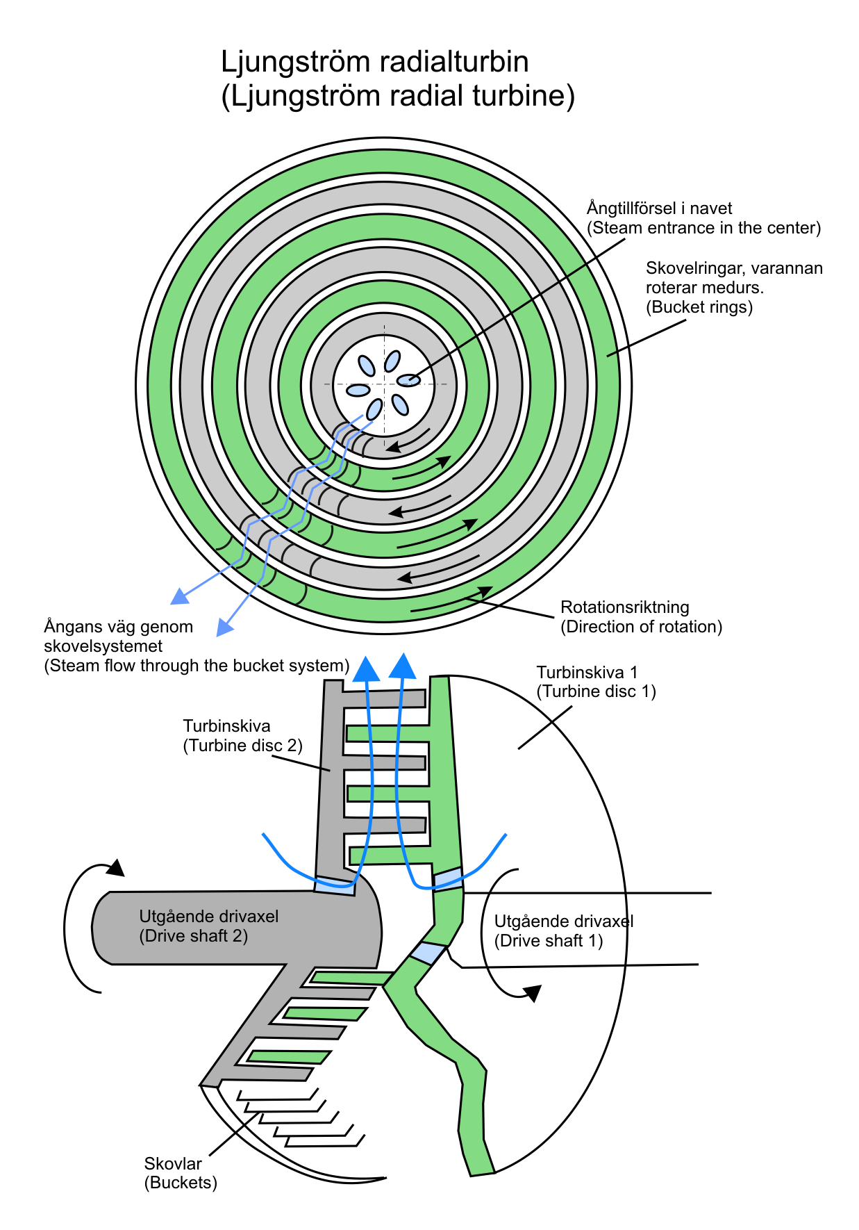
However, radial-outflow steam turbines, which comprise many stages, have been widely accepted in Europe. For example, the Ljungström steam turbine creates a tremendous increase in the specific volume of steam and makes the radial outflow flow path almost essential.
Radial Hydraulic Turbines
In radial flow hydraulic turbines, the liquid flows mainly in a plane perpendicular to the rotation axis. Reaction hydraulic turbines are divided into radial and axial flow turbines. For example, Francis turbines are reaction turbines developed for pressure heads from 600 m to 30 m. In such flow units, the flow enters the turbine runner radially and leaves axially.
In radial flow reaction turbines, the water can flow radially from out to inside (inward radial flow turbine) or from inside to outside (outward radial flow turbine).
Radial Outflow Turbines
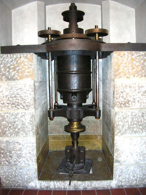
The early hydraulic turbines were radial outflow turbines. The Hero’s turbine is an example of these traditional turbines. The Hero’s turbine is applied as sprinklers on grasses to wet them. Fourneyron, a French engineer, developed the first successful commercial hydraulic turbine of the outflow radial type.
In these turbines, the water enters the center of the turbine wheel and then flows towards the outside of the wheel. A runner surrounds the guide mechanism. The inner diameter of the runner of the outward flow reaction turbine is the inlet, and the outer diameter is the outlet.
In this turbine type, the speed is challenging to control. Also, it is usually used in small hydraulic heads.
Radial Inflow Turbine
The radial inflow hydraulic turbine first appeared as an operating unit for power generation in the hydraulic turbine field. The most common water turbine is the Francis turbine. Francis is an inward flow reaction turbine that combines the concepts of radial and axial flow. The inward-flow radial turbine includes large ranges of power generation, mass flow rates, and rotational speeds. It can be used in huge hydroelectric power generation units producing hundreds of megawatts as well as small closed cycle gas turbines to generate a few kilowatts of power.
Francis turbines are the most commonly used water turbines today. They work in a range of 10 to 650 meters of head and are mainly used for electrical power generation. The power ranges from 10 to 750 MW, except for mini-river hydros.
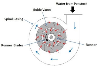
A casing is required to hold the water flow. The turbine is positioned between the high-pressure water reservoir and the low-pressure water discharge line, normally at the base of a dam. The inlet is in the form of a spiral. Guide vanes lead the water tangentially to the turbine runner. This radial flow affects the runner blades, causing the runner to rotate. The guide vanes (wicket gate) may be adjusted to allow the turbine to work efficiently in a range of water flow conditions.
Runner diameters are from 1 to 10 meters. The rotational speed of the turbine ranges from 83 to 1,000 rpm. The shafts of medium and large Francis turbines are usually constructed vertically. The vertical arrangement is also used for small-size turbines, but usually they have a horizontal shaft.
Components of Radial Flow Hydraulic Turbines
The following are the main components of a radial water turbine.
Casing
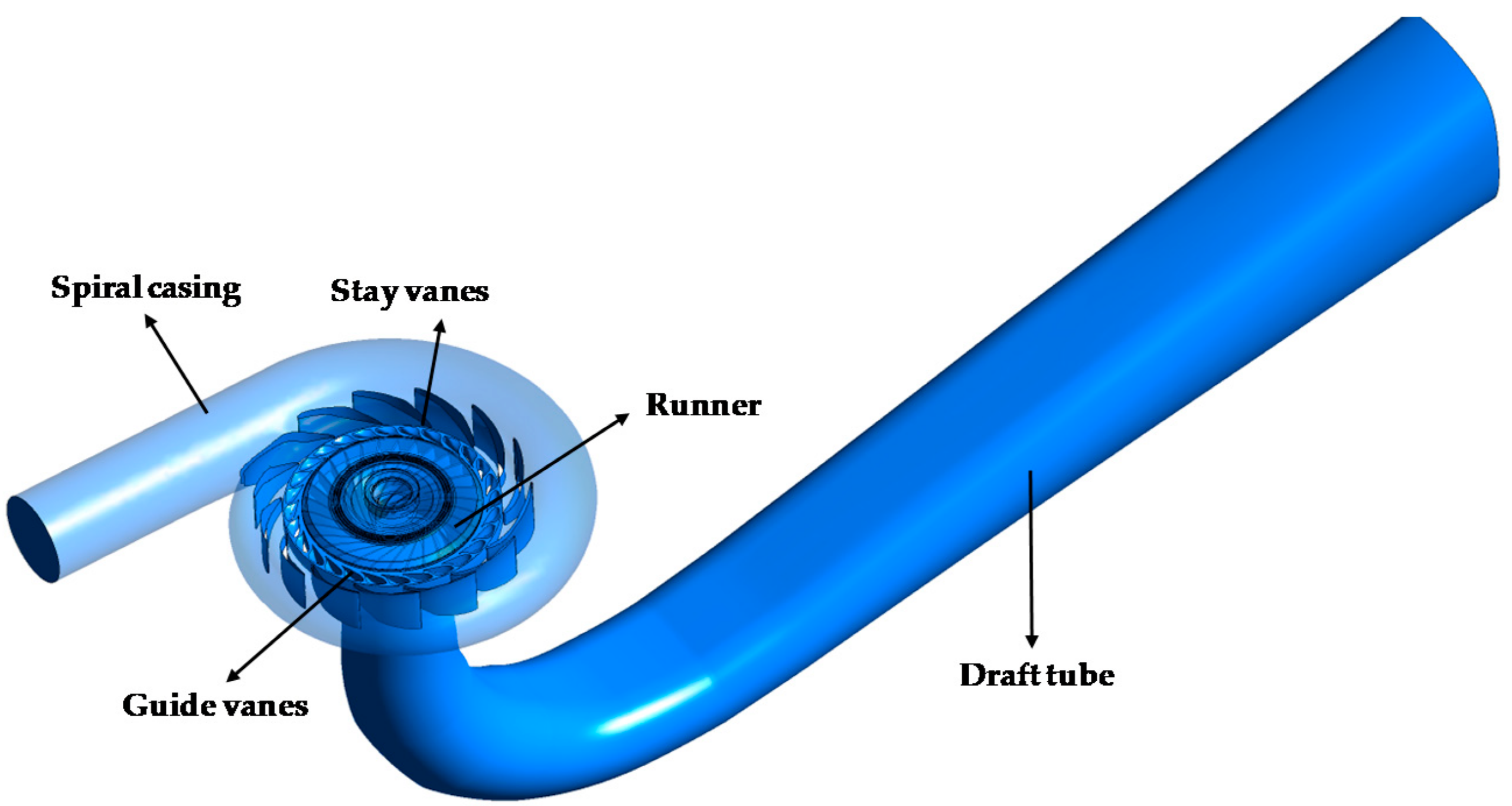
In a radial flow water turbine, the casing is always full of water. Water enters the casing from the penstock. The casing of a radial flow hydraulic turbine completely surrounds the turbine runner. The casing of a radial flow turbine is in a spiral shape so that water can enter the runner at a constant speed throughout the circumference of the runner.
The area of cross-section of the casing decreases gradually. The casing is built of concrete, cast steel, or plate steel.
Stay Vanes
Stay vanes are fixed in position. They reduce the swirling of water due to radial flow when the water enters the runner blades. Therefore, they make the turbine more efficient.
Guide Vanes
The guide vanes are basically installed on a stationary circular wheel around the turbine runner. The guide vanes allow the water to hit the blades on the turbine runner without shock at the inlet.
The guide vanes are not stationary similar to stay vanes. The width between two adjacent vanes of the guide mechanism can be adjusted using a mechanism to alter the volume of water striking the runner blades. They also provide the proper angle of water hitting the turbine blades to increase efficiency. Thus, the guide vanes allow more control of the turbine power output according to the load on the turbine.
Runner
The runner of a radial flow hydraulic turbine consists of a circular wheel on which a series of radially curved blades are mounted. The surface of these blades is made smooth to minimize hydraulic losses.
The curved blades are shaped so that the water can enter and exit the runner without shock.
The runner is fixed with the shaft. Material of casting of the runner is cast steel, cast iron and stainless steel.
Draft Tube
The pressure at the outlet of the radial flow turbine runner is usually lower than the atmospheric pressure. So, water at the exit cannot be directly drained to the tailrace. Therefore, a tube or pipe with a gradually increasing cross-sectional area is used to discharge the water from the outlet of the turbine runner to the tailrace. This tube or pipe is known as a draft tube.
Radial Gas Turbines
Modern small gas turbines are technically complicated machines, including many rotating parts, bearings, seals, lubrication systems, and advanced electronic controls. Most gas turbine designs are optimized for maximum efficiency but generally are not portable and cannot manage severe environmental conditions; As a result, ruggedness is usually sacrificed for efficiency. Although this is desirable for most large power plant applications, it is not feasible for small, portable power generation purposes.
Compared to axial flow turbines, radial turbines can work with relatively higher pressure ratios per stage with lower flow rates. Therefore, these machines are in the lower ranges of specific speed and power. For high-temperature purposes, cooling the rotor blade in radial stages is not as simple as in axial turbine stages. Changeable angle nozzle blades, even in off-design conditions, allow higher stage efficiencies in a radial turbine stage.
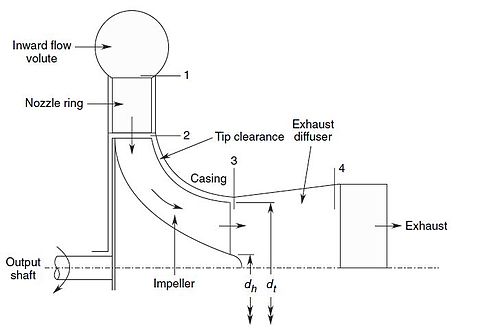
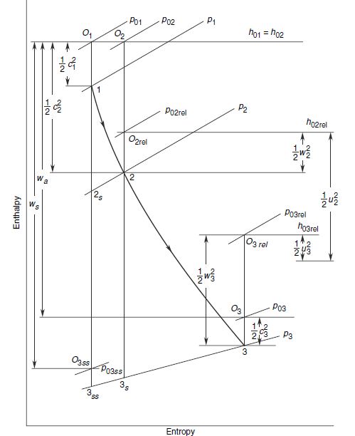
The working of a radial gas turbine is based on the following h-s (enthalpy-entropy) diagram. The gas stagnation state at the nozzle entry is described by point 01. In the nozzles, the gas expands adiabatically with increasing the velocity from c1 to c2 from a pressure p1 to p2. As this is an energy transfer process, the stagnation enthalpy continues constant, but the stagnation pressure decreases due to losses (i.e., p01 > p02). The energy transfer occurs in the rotor along with an energy transformation process.
A single disk radial flow gas turbine operates on a straight radial flow scheme with no axial flow turning. This design contains only two main components:
- Rotor disk that includes a centrifugal compressor and high impulse outward flow turbine attached to an electric generator (and a starter motor)
- Stator shroud disk that contains a combustor and nozzles, and fuel lines which are connected to the stator shroud disk and ducted directly into the combustor
The stage output work is less than the isentropic enthalpy drop due to the aerodynamic losses in the stage. The actual power on the turbine shaft is equal to the work of the stage minus the losses due to bearing friction and rotor disc.
According to the above diagram, the stage efficiency can be calculated by:
\eta _{ts}=\frac{h_{01}-h_{03}}{h_{01}-h_{3ss}}
Stage Losses
Stage losses include the following items:
Scroll and Nozzle Ring Losses Due to Friction and Separation
They are dependent on the geometry and the skin friction coefficient of these components.
Rotor Blade Channels Losses Due to Friction and Separation
These losses are also dictated to the system by the channel geometry, skin friction coefficient, and the ratio of the relative velocities w3/w2.
Diffuser Losses Due to Friction and Separation
These are generally governed by the diffuser geometry and the rate of diffusion.
Secondary Losses
These losses are due to circulating flows in different flow passages and are mainly determined by the aerodynamic loading on the blades. The principal parameters governing secondary losses are b2/d2, d3/d2, and the hub-to-tip ratio at the rotor outlet.
Shock or Incidence Losses
When working off-design, there are further losses in the nozzle and rotor blade due to the improper attack angle of the flow at the leading edges of the blades. These losses are commonly referred to as shock loss but have nothing to do with shock waves.
Tip Clearance Losses
Tip clearance losses are added to the system because of the flow over the tips of the rotor blades which does not provide any energy transfer.
Inward Flow Radial Turbine
In the figure below, you can see the velocity triangle for an inward radial turbine. c2 is the absolute velocity, and the radial and tangential components are cr2 and cq2, respectively. The relative flow velocity and the peripheral rotor speed are w2 and u2, respectively. Therefore, the air angle at the rotor blade inlet is expressed as:
\tan \theta _{2}=\frac{c_{r2}}{c_{\theta 2}-u_{2}}
The inward flow radial gas turbine has been used to power automotive turbochargers, expansion units in gas liquefaction, aircraft auxiliary power units, and cryogenic systems. Additionally, they can be applied as a component of the small gas turbine units (10 kW) for space power generation. It has been recognized for primary use in automobiles and in helicopters.
A cooled, high-efficiency inward flow radial turbine can offer improved performance as the gas generator turbine in an advanced turboshaft engine. Some minor improvements in current technology levels are needed to enhance this type of application. However, the designers of this new generation of inward flow radial turbines face significant problems, especially in the development of advanced rotor cooling techniques or ceramic shock-resistant rotors.
Outward Flow Radial Turbines
In an outward flow radial turbine stage, the gas or steam flows from a smaller to a larger diameter. The stage includes a pair of stationary and moving blades. The increasing cross-sectional area at larger diameters contains the expanding gas.
This configuration is not common in steam and gas turbines. The only one commonly used is the Ljungstrom double rotation type turbine consisting of cantilever blade rings projecting from two discs that rotate in opposite directions. The relative peripheral velocity of blades in two adjacent rows is high, relative to each other. This provides a more enthalpy drop per stage.
Buy Equipment or Ask for a Service
By using Linquip RFQ Service, you can expect to receive quotations from various suppliers across multiple industries and regions.
Click Here to Request a Quotation From Suppliers and Service Providers
Read More In Linquip
- Types of Turbines: Classifications and Types
- The 8 Best Home Wind Turbines in 2021
- Mixed Flow Turbine
- Low Head Turbines
- Hydrogen Gas Turbine: All You Need to Know
- What is Tesla Turbine and How Does it Works?
- What is Mixed Flow Turbine? Basics, Advantages, and Applications
- Axial Flow Turbines and Working Principles
- Cross-Flow Turbine: Working Principle, Components, and Advantages


Problems required for our practice
So please sent
Thank you
Thanks for visiting our website. We hope to hear more from you. You are also encouraged to visit our other posts on the Linquip website.