Model YLAA Air-Cooled Scroll Chillers Style A - Aireyork
Model YLAA Air-Cooled Scroll Chillers Style A - Aireyork
Model YLAA Air-Cooled Scroll Chillers Style A - Aireyork

Create successful ePaper yourself
Turn your PDF publications into a flip-book with our unique Google optimized e-Paper software.
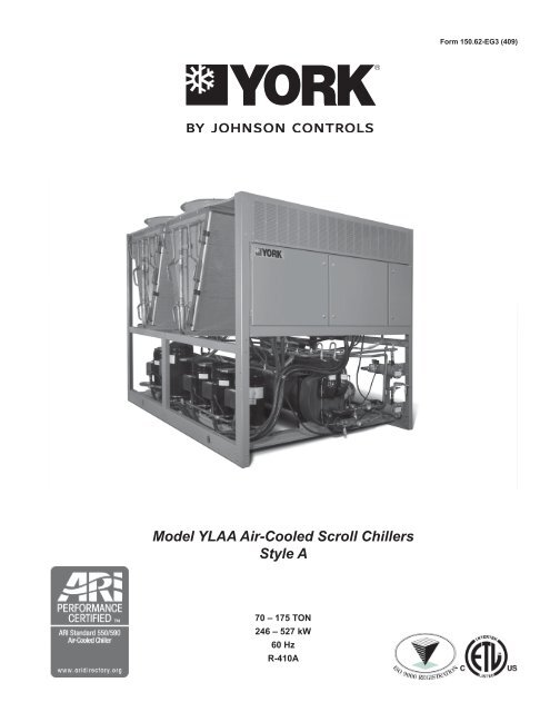
<strong>Model</strong> <strong>YLAA</strong> <strong>Air</strong>-<strong>Cooled</strong> <strong>Scroll</strong> <strong>Chillers</strong><br />
<strong>Style</strong> A<br />
70 – 175 TON<br />
246 – 527 kW<br />
60 Hz<br />
R-410A<br />
Form 150.62-EG3 (409)
Table of contents<br />
Form 150.62-EG3 (409) ......................................................................................................................................................................................... 1<br />
Introduction ........................................................................................................................................................................................................... 3<br />
Specifications ....................................................................................................................................................................................................... 4<br />
Microcomputer Control Center ........................................................................................................................................................................... 5<br />
Accessories and Options .................................................................................................................................................................................... 7<br />
Design Parameters ............................................................................................................................................................................................. 10<br />
Water Pressure Drop ...........................................................................................................................................................................................11<br />
Selection Criteria and Procedures .................................................................................................................................................................... 12<br />
Pump Selection Criteria ..................................................................................................................................................................................... 14<br />
Pump Pressure Drop Curves............................................................................................................................................................................. 16<br />
Single Pump Curves........................................................................................................................................................................................... 18<br />
Dual Pump Curves.............................................................................................................................................................................................. 19<br />
Ratings - 60 Hz .................................................................................................................................................................................................... 20<br />
Part Load Ratings - Standard Efficiency .......................................................................................................................................................... 28<br />
Part Load Ratings - High Efficiency .................................................................................................................................................................. 29<br />
Physical Data - English ...................................................................................................................................................................................... 30<br />
Dimensions - Four Fan Units ............................................................................................................................................................................. 32<br />
Dimensions - Five Fan Units ............................................................................................................................................................................. 33<br />
Dimensions - Six Fan Units ............................................................................................................................................................................... 34<br />
Dimensions - Eight Fan Units ............................................................................................................................................................................ 35<br />
Dimensions - Ten Fan Units .............................................................................................................................................................................. 36<br />
Isolator Locations ............................................................................................................................................................................................... 37<br />
Isolator Details .................................................................................................................................................................................................... 40<br />
Electrical Notes................................................................................................................................................................................................... 43<br />
Electrical Data w/o Pumps ................................................................................................................................................................................. 44<br />
Wiring Lugs ......................................................................................................................................................................................................... 48<br />
Electrical Data w/ Pumps ................................................................................................................................................................................... 50<br />
Wiring Diagram ................................................................................................................................................................................................... 60<br />
Elementary Wiring ............................................................................................................................................................................................. 62<br />
Condenser Fan Mapping and Sequencing ....................................................................................................................................................... 64<br />
Compressor Wiring ............................................................................................................................................................................................ 65<br />
Power Options Connection Diagram ................................................................................................................................................................ 66<br />
Power Panel ........................................................................................................................................................................................................ 67<br />
Dual Pump Wiring ............................................................................................................................................................................................... 68<br />
Wiring .................................................................................................................................................................................................................. 69<br />
MicroPanel Connections .................................................................................................................................................................................... 70<br />
Application Data ................................................................................................................................................................................................. 73<br />
Guide Specifications .......................................................................................................................................................................................... 74<br />
York Chiller<br />
NOMENCLATURE<br />
The model number denotes the following characteristics of the unit:<br />
A = Americas<br />
Four Digit Unit Number<br />
0070<br />
T E<br />
E 410A<br />
Unit Designator<br />
S = Standard Efficiency<br />
H = High Efficiency<br />
Y = Standard Efficiency (round tube)<br />
Z = High Efficiency (round tube)<br />
jOHNSON CONTROLS
Introduction<br />
jOHNSON CONTROLS<br />
FORM 150.62-EG3 (409)<br />
Johnson Controls, the leader in equipment<br />
controls and HVAC equipment is proud to<br />
offer the YORK air-cooled scroll chiller.<br />
This all-in-one package is a true plug and<br />
play system that provides superb efficiency<br />
and performance. The chiller is completely self-contained and is designed for outdoor (roof or ground<br />
level) installation. An optional hydronic pump kit makes service replacement or new building installations<br />
very convenient. Each unit includes zero-ozone-depletion refrigerant (R-410A), hermetic scroll compressors,<br />
a liquid evaporator, air cooled condenser, and a weather resistant microprocessor control center,<br />
all mounted on a formed steel base.<br />
ENviRONMENTAL REspONsibiLiTy …sTANdARd<br />
TEMPO makes you the leader in environmental practices<br />
through innovation, not added cost. With the combination of R-<br />
410A refrigerant and a 0-50% reduction of refrigerant used vs.<br />
similar chillers, the TEMPO chiller provides you with the most<br />
ecologically friendly equipment. Partnered with it’s low sound<br />
properties (for noise pollution prevention), this chiller is a true<br />
earth-friendly offering.<br />
REdUCEd TOTAL COsT OF OWNERsHip...<br />
Industry leading energy efficiency, easy maintenance and<br />
durability minimize your cost of ownership. Efficiency; environmentally<br />
responsibility that pays you back…<br />
• Real world energy efficiency is measured in IPLV (part load)<br />
performance<br />
• Tempo’s industry leading IPLV’s deliver cash to your bottom<br />
line<br />
• Serviceability…Easier maintenance pays twice: sustained<br />
chiller efficiency and lower cost maintenance contracts<br />
• Corrosion resistant condenser coils extend life and improve<br />
performance<br />
MORE bUiLdiNG…LEss CHiLLER<br />
TEMPO offers a lighter, smaller and quieter chiller minimizing<br />
your installed cost and maximizing usable building space.<br />
Tempo<br />
• More space for you<br />
New pace…New World<br />
Try keeping up with our Tempo!<br />
• Smaller chiller footprint saves valuable space<br />
• Tempo is the lowest weight chiller available, lighter than our<br />
previous generation chiller by 0- 5%<br />
• Hydronic pump kit option can save both space and cost by<br />
integrating the chilled water pumps as a factory mounted<br />
chiller option<br />
• Standard low sound and affordable sound attenuation options<br />
allow flexibility in locating chiller and reduce cost for<br />
field constructed sound barriers<br />
MANy AppLiCATiONs, ONE TEMpO!<br />
Performance, sound and hydronic pump kits are all configurable<br />
to suit your many needs… Performance can be configured with<br />
standard and high full-load efficiency models (an industry first)<br />
• Multiple sound configurations…only spend on what you<br />
need.<br />
• Pumps can be factory mounted<br />
• Hydronic pump kits can be configured for a wide range of flow<br />
and head pressure with single or dual (standby) pump<br />
• Standard corrosion resistance for coastal applications<br />
• Small weight and footprint allow you maximum choice in locating<br />
the chiller
Specifications<br />
GENERAL<br />
The 70 - 175 Ton ( 46 - 61 ) yLAA models are shipped<br />
complete from the factory ready for installation and use.<br />
The unit is pressure-tested, evacuated, and fully charged<br />
with a zero Ozone Depletion Potential Refrigerant R-<br />
410A and includes an initial oil charge. After assembly, a<br />
complete operational test is performed with water flowing<br />
through the evaporator to assure that the refrigeration<br />
circuit operates correctly.<br />
The unit structure is heavy-gauge, galvanized steel. This<br />
galvanized steel is coated with baked-on powder paint,<br />
which, when subjected to ASTM B117 1000 hour, salt<br />
spray testing, yields a minimum ASTM 1654 rating of<br />
“6”. Units are designed in accordance with NFPA 70 (National<br />
Electric Code), ASHRAE/ANSI 15 Safety code for<br />
mechanical refrigeration, ASME and rated in accordance<br />
with ARI Standard 550/590.<br />
COMpREssORs<br />
The chiller has suction-gas cooled, hermetic, scroll compressors.<br />
The <strong>YLAA</strong> compressors incorporate a compliant<br />
scroll design in both the axial and radial direction. All rotating<br />
parts are statically and dynamically balanced. A large internal<br />
volume and oil reservoir provides greater liquid tolerance.<br />
Compressor-crankcase heaters are also included for extra<br />
protection against liquid migration.<br />
EvApORATOR<br />
The evaporator is equipped with a heater controlled by<br />
a separate thermostat. The heater provides freeze protection<br />
for the evaporator down to - 0 o F (- 9°C) ambient.<br />
The evaporator is covered with 3/4” flexible, closed-cell,<br />
foam insulation (K=0. 5).<br />
The water baffles are constructed of galvanized steel to<br />
resist corrosion. The removable heads allow access to<br />
the internally enhanced, seamless, copper tubes. Vent<br />
and drain connections are included.<br />
Water inlet and outlet connections are grooved for compatibility<br />
with field supplied ANSI/AWWA C-606 couplings.<br />
CONdENsER<br />
Coils - Condenser coils are made of a single material to<br />
avoid galvanic corrosion due to dissimilar metals. Coils<br />
and headers are brazed as one piece. Integral sub cooling<br />
is included. The design working pressure of the coil<br />
is 650 PSIG (45 bar). Condenser coil shall be pressure<br />
washable up to 1500 psi washer.<br />
Fans – The condenser fans are composed of corrosion<br />
resistant aluminum hub and glass-fiber-reinforced polypropylene<br />
composite blades molded into a low-noise airfoil<br />
section. They are designed for maximum efficiency and<br />
are statically and dynamically balanced for vibration-free<br />
operation. They are directly driven by independent motors,<br />
and positioned for vertical air discharge. The fan guards<br />
are constructed of heavy-gauge, rust-resistant, coated<br />
steel. All blades are statically and dynamically balanced<br />
for vibration-free operation.<br />
Motors – The fan motors are Totally Enclosed <strong>Air</strong>-Over, squirrel-cage<br />
type, current protected. They feature ball bearings<br />
that are double-sealed and permanently lubricated.<br />
Ambient Kit (High) – Required if units are to operate<br />
when the ambient temperature is above 115°F (46°C).<br />
Includes discharge pressure transducers.<br />
4 jOHNSON CONTROLS
Microcomputer Control Center<br />
All controls are contained in a NEMA R/1 cabinet with<br />
hinged outer door and includes:<br />
Liquid Crystal Display with Light Emitting Diode backlighting<br />
for outdoor viewing:<br />
Two display lines<br />
Twenty characters per line<br />
Color coded 1 -button non-tactile keypad with sections<br />
for:<br />
dispLAy/pRiNT of typical information:<br />
Chilled liquid temperatures<br />
Ambient temperature<br />
System pressures (each circuit)<br />
Operating hours and starts (each compressor)<br />
Print calls up to the liquid crystal display:<br />
Operating data for the systems<br />
History of fault shutdown data for up to<br />
the last six fault shutdown conditions<br />
An RS- port, in conjunction with this<br />
FIG.1 – CONTROL PANEL COMPONENTS<br />
jOHNSON CONTROLS<br />
FORM 150.62-EG3 (409)<br />
press-to-print button, is provided to permit<br />
the capability of hard copy print-outs via a<br />
separate printer (by others).<br />
ENTRy section to:<br />
ENTER setpoints or modify system values<br />
sETpOiNTs updating can be performed to:<br />
Chilled liquid temperature setpoint and range<br />
Remote reset temperature range<br />
Set daily schedule/holiday for start/stop<br />
Manual override for servicing<br />
Low and high ambient cutouts<br />
Number of compressors<br />
Low liquid temperature cutout<br />
Low suction pressure cutout<br />
High discharge pressure cutout<br />
Anti-recycle timer (compressor start cycle<br />
time)<br />
Anti-coincident timer (delay compressor<br />
starts)<br />
UNiT section to:<br />
Set time<br />
Set unit options<br />
UNiT ON/OFF switch<br />
The microprocessor control center is capable of displaying<br />
the following:<br />
• Return and leaving liquid temperature<br />
• Low leaving liquid temperature cutout setting<br />
• Low ambient temperature cutout setting<br />
• Outdoor air temperature<br />
• English or Metric data<br />
• Suction pressure cutout setting<br />
• Each system suction pressure<br />
• Discharge pressure (optional)<br />
• Liquid Temperature Reset via a johnson Controls ISN<br />
DDC or Building Automation System (by others) via:<br />
- a 4-20 milliamp or 0 -10 VDC input<br />
• Anti-recycle timer status for each system<br />
• Anti-coincident system start timer condition<br />
• Compressor run status<br />
• No cooling load condition<br />
• Day, date and time<br />
• Daily start/stop times<br />
• Holiday status<br />
• Automatic or manual system lead/lag control<br />
• Lead system definition<br />
• Compressor starts & operating hours<br />
5
Microcomputer Control Center - continued<br />
(each compressor)<br />
• Status of hot gas valves, evaporator heater<br />
and fan operation<br />
• Run permissive status<br />
• Number of compressors running<br />
• Liquid solenoid valve status<br />
• Load & unload timer status<br />
• Water pump status<br />
Provisions are included for: pumpdown at shutdown;<br />
optional remote chilled water temperature reset and two<br />
steps of demand load limiting from an external building<br />
automation system. Unit alarm contacts are standard.<br />
The operating program is stored in non-volatile memory<br />
(EPROM) to eliminate chiller failure due to AC powered<br />
failure/battery discharge. Programmed setpoints are retained<br />
in lithium battery-backed RTC memory for 5 years<br />
minimum.<br />
COMMUNiCATiONs<br />
• Native communication capability for BACnet (MS/TP)<br />
and Modbus<br />
• Optional communciation available for N and LON via<br />
eLink option<br />
HiGH AMbiENT KiT<br />
Allows units to operate when the ambient temperature<br />
is above 115°F (46°C). Includes sun shield panels and<br />
FAN<br />
CONTACTOR<br />
XTBF1<br />
FAN<br />
FUSE<br />
COMPRESSOR<br />
CONTACTORS<br />
FAN<br />
CONTACTORS<br />
FiG. 2 – POWER PANEL COMPONENTS<br />
DISCONNECT<br />
SWITCH<br />
GROUND<br />
LUG<br />
discharge pressure transducers.<br />
bUiLdiNG AUTOMATiON sysTEM iNTERFACE<br />
The factory addition of a Printed Circuit Board to accept a<br />
4-20 milliamp or 0-10VDC input to reset the leaving chiller<br />
liquid temperature from a Building Automation System.<br />
(Factory-mounted)<br />
- (The standard unit capabilities include remote startstop,<br />
remote water temperature reset via up to two<br />
steps of demand (load) limiting depending on model.)<br />
- (The standard control panel can be directly connected<br />
to a johnson Controls Building Automated System via<br />
the standard on-board RS communication port.)<br />
pOWER pANEL<br />
Each panel contains:<br />
• Compressor power terminals<br />
• Compressor motor starting contactors per l.E.C.<br />
• Control power terminals to accept incoming for<br />
115-1-60 control power<br />
• Fan contactors & overload current protection<br />
The power wiring is routed through liquid-tight conduit to<br />
the compressors and fans.<br />
FAN<br />
CONTACTORS<br />
COMPRESSOR<br />
CONTACTORS<br />
FAN<br />
FUSE<br />
FAN<br />
CONTACTOR<br />
COMPRESSOR<br />
OVERLOADS<br />
6 jOHNSON CONTROLS
Accessories and Options<br />
pOWER OpTiONs:<br />
COMpREssOR pOWER CONNECTiONs – Single-point<br />
terminal block connection(s) are provided as standard.<br />
The following power connections are available as options.<br />
(See electrical data for specific voltage and options availability.)<br />
(Factory-mounted)<br />
siNGLE-pOiNT sUppLy TERMiNAL bLOCK – Includes<br />
enclosure, terminal-block and interconnecting wiring to<br />
the compressors. Separate external protection must be<br />
supplied, by others, in the incoming compressor-power<br />
wiring. (Do not include this option if either the Single-Point<br />
Non-Fused Disconnect Switch or Single-Point Circuit<br />
Breaker options have been included.)<br />
siNGLE-pOiNT NON-FUsEd disCONNECT sWiTCH<br />
– Unit-mounted disconnect switch(es) with external, lockable<br />
handle (in compliance with Article 440-14 of N.E.C.),<br />
can be supplied to isolate the unit power voltage for<br />
servicing. Separate external fusing must be supplied, by<br />
others in the power wiring, which must comply with the<br />
National Electrical Code and/or local codes.<br />
siNGLE-pOiNT NON-FUsEd disCONNECT sWiTCH<br />
WiTH iNdividUAL sysTEM bREAKERs - Includes<br />
unit-mounted disconnect switch with external, lockable<br />
handles (in compliance with Article 440-14 of N.E.C.) to<br />
isolate unit power voltage for servicing. Factory interconnecting<br />
wiring is provided from the disconnect switch to<br />
factory supplied system circuit breakers.<br />
siNGLE-pOiNT CiRCUiT bREAKER – A unit mounted<br />
circuit breaker with external, lockable handle (in compliance<br />
with N.E.C. Article 440-14), can be supplied to isolate<br />
the power voltage for servicing. (This option includes the<br />
Single-Point Power connection.)<br />
CONTROL TRANsFORMER – Converts unit power voltage<br />
to 115-1-60 (0.5 or 1.0 KVA capacity). Factory mounting<br />
includes primary and secondary wiring between the<br />
transformer and the control panel. (Factory-mounted)<br />
pOWER FACTOR CORRECTiON CApACiTORs – Will<br />
correct unit compressor power factors to a 0.90-0.95.<br />
(Factory-mounted)<br />
CONTROL OpTiONs:<br />
AMbiENT KiT (LOW) – Units will operate to 0°F (-1°C).<br />
This accessory includes all necessary components to permit<br />
chiller operation to 0°F (-18°C). (This option includes<br />
the Discharge Pressure Transducer / Readout Capability<br />
option.) For proper head pressure control in applications<br />
below 0°F (-1°C) where wind gusts may exceed 5 mph,<br />
jOHNSON CONTROLS<br />
FORM 150.62-EG3 (409)<br />
it is recommended that Optional Condenser Louvered<br />
Enclosure Panels also be included. (Factory-mounted)<br />
LANGUAGE LCd ANd KEypAd dispLAy – Spanish,<br />
French, German, and Italian unit LCD controls and keypad<br />
display available. Standard language is English.<br />
COMpREssOR, pipiNG, EvApORATOR<br />
OpTiONs:<br />
FLANGEs (ANsi/AWWA C-606 COUpLiNGs TypE)<br />
– Consists of ( ) Flange adapter for grooved end pipe<br />
(standard 150 psi [10.5 bar] evaporator). (Not available<br />
on optional DX evaporator 300 PSIG DWP waterside.)<br />
(Field-mounted)<br />
LOW TEMpERATURE bRiNE – Required for brine<br />
chilling below 0°F (-1°C) leaving brine temperature.<br />
Option includes resized thermal expansion valve. (Factory-mounted)<br />
CHiCAGO COdE RELiEF vALvEs – Unit will be provided<br />
with relief valves to meet Chicago code requirements.<br />
(Factory-Mounted)<br />
sERviCE sUCTiON isOLATiON vALvE – Service suction<br />
discharge (ball-type) isolation valves are added to unit<br />
per system (discharge service ball-type isolation valve is<br />
standard on each circuit). (Factory-Mounted)<br />
HOT GAs by-pAss – Permits continuous, stable operation<br />
at capacities below the minimum step of compressor<br />
unloading to as low as 5% capacity (depending<br />
on both the unit and operating conditions) by introducing<br />
an artificial load on the evaporator. Hot gas by-pass is<br />
installed on only refrigerant system #1 on two-circuited<br />
units. (Factory-Mounted)<br />
FLOW sWiTCH – The flow switch or its equivalent must<br />
be furnished with each unit.<br />
150 psig (10.5 bar) dWp – For standard units. johnson<br />
Controls model F61MG-1C Vapor-proof SPDT, NEMA<br />
R switch (150 PSIG [10.5 bar] DWP), - 0°F to 50°F<br />
(- 9°C to 1 1°C), with 1" NPT connection for upright<br />
mounting in horizontal pipe. (Field-mounted)<br />
diFFERENTiAL pREssURE sWiTCH – Alternative to an<br />
above mentioned flow switch. Pretempco model DPS300A-<br />
P40PF-8 58 -5 ( 00 psi max. working pressure), SPDT 5<br />
amp 125/250VAC switch, Range 3 - 40 PSID, deadband<br />
0.5 - 0.8 psi, with 1/4” NPTE Pressure Connections.<br />
HydRO-KiT – Factory installed Hydro-Kit suitable for water<br />
glycol systems with up to 5% glycol at leaving tempera-<br />
7
Accessories and Options - continued<br />
tures down to 0 F. The Hydro-kit option is available in a<br />
single or dual configuration (dual as standby duty only), with<br />
totally enclosed permanently lubricated pump motors.<br />
The hydro-kit option comes standard with a balancing valve,<br />
flow switch, pressure ports, suction guide, strainer, bleed<br />
and drain valves and frost protection.<br />
Expansion tanks are optional within the Hydro-Kit option.<br />
CONdENsER ANd CAbiNET OpTiONs:<br />
Condenser coil protection against corrosive environments<br />
is available by choosing any of the following options. For<br />
additional application recommendations, refer to FORM<br />
150.1 -ES1. (Factory-Mounted)<br />
pOsT-COATEd dippEd CONdENsER COiLs – The<br />
unit is built with dipped-cured condenser coils. This is the<br />
choice for corrosive applications (with the exception of<br />
strong alkalies, oxidizers and wet bromine, chlorine and<br />
fluorine in concentrations greater than 100 ppm).<br />
ENCLOsURE pANELs (UNiT) – Tamperproof Enclosure<br />
Panels prevent unauthorized access to units. Enclosure<br />
Panels can provide an aesthetically pleasing alternative<br />
to expensive fencing. Additionally, for proper head pressure<br />
control, johnson Controls recommends the use of<br />
Condenser Louvered Panels for winter applications where<br />
wind gusts may exceed five miles per hour. The following<br />
types of enclosure panels are available:<br />
WiRE pANELs (FULL UNiT) – Consists of welded<br />
wire-mesh guards mounted on the exterior of the unit.<br />
Prevents unauthorized access, yet provides free air flow.<br />
(Factory-Mounted)<br />
WiRE/LOUvEREd pANELs – Consists of welded wiremesh<br />
panels on the bottom part of unit and louvered<br />
panels on the condenser section of the unit. (Factory-<br />
mounted).<br />
LOUvEREd pANELs (CONdENsER COiL ONLy)<br />
– Louvered panels are mounted on the sides and ends of<br />
the condenser coils for protection. (Factory-Mounted)<br />
LOUvEREd pANELs (FULL UNiT) – Louvered panels<br />
surround the front, back, and sides of the unit. They<br />
prevent unauthorized access and visually screen unit<br />
components. Unrestricted air flow is permitted through<br />
generously sized louvered openings. This option is applicable<br />
for any outdoor design ambient temperature up<br />
to 115°F (46°). (Factory-Mounted)<br />
COiL ENd HAiL GUARd – Louvered panel attached to<br />
exposed coil end. (Factory-Mounted)<br />
sOUNd ATTENUATiON – One or both of the following<br />
sound attenuation options are recommended for residential<br />
or other similar sound sensitive locations:<br />
COMpREssOR ACOUsTiC sOUNd bLANKET – Each<br />
compressor is individually enclosed by an acoustic sound<br />
blanket. The sound blankets are made with one layer of<br />
acoustical absorbent textile fiber of 5/8" (15mm) thickness;<br />
one layer of anti-vibrating heavy material thickness of 1/8"<br />
(3mm). Both are closed by two sheets of welded PVC,<br />
reinforced for temperature and UV resistance. (Factory-<br />
Mounted)<br />
ULTRA QUiET FANs – Lower RPM, 8-pole fan motors<br />
are used with steeper-pitch fans. (Factory-Mounted)<br />
vibRATiON isOLATORs – Level adjusting, spring type 1"<br />
(25.4mm) or seismic deflection or neoprene pad isolators<br />
for mounting under unit base rails. (Field-mounted)<br />
8 jOHNSON CONTROLS
COMPRESSORS<br />
MICROCHANNEL<br />
COILS<br />
FORMED<br />
BASE<br />
RAIL<br />
FiG.3 – GENERAL UNIT COMPONENTS<br />
jOHNSON CONTROLS<br />
FAN DECK<br />
POWER<br />
PANEL<br />
EVAPORATOR<br />
CONTROL<br />
PANEL<br />
TXV<br />
VALVES<br />
FORM 150.62-EG3 (409)<br />
LIQUID<br />
TIGHT<br />
CONDUIT<br />
FILTER<br />
DRIERS<br />
SIGHT<br />
GLASS<br />
9
Design Parameters<br />
Unit Designation<br />
NOTEs:<br />
Nominal Evaporator Water Flow<br />
Temperature (°F) Water Flow (gpm) <strong>Air</strong> On Condenser (°F)<br />
MIN 1 MAX 2 MIN MAX MIN 3 MAX 4<br />
<strong>YLAA</strong>0070SE 40 55 60 285 0 125<br />
<strong>YLAA</strong>0080SE 40 55 100 355 0 125<br />
<strong>YLAA</strong>0090SE 40 55 140 625 0 125<br />
<strong>YLAA</strong>0100SE 40 55 100 385 0 125<br />
<strong>YLAA</strong>0115SE 40 55 100 385 0 125<br />
<strong>YLAA</strong>0120SE 40 55 150 625 0 125<br />
<strong>YLAA</strong>0135SE 40 55 120 625 0 125<br />
<strong>YLAA</strong>0150SE 40 55 120 625 0 125<br />
<strong>YLAA</strong>0155SE 40 55 150 625 0 125<br />
<strong>YLAA</strong>0170SE 40 55 120 625 0 125<br />
High Efficiency<br />
<strong>YLAA</strong>0091HE 40 55 100 385 0 125<br />
<strong>YLAA</strong>0101HE 40 55 100 385 0 125<br />
<strong>YLAA</strong>0125HE 40 55 100 385 0 125<br />
<strong>YLAA</strong>0141HE 40 55 150 625 0 125<br />
<strong>YLAA</strong>0156HE 40 55 120 625 0 125<br />
<strong>YLAA</strong>0175HE 40 55 180 650 0 125<br />
1. For leaving brine temperature below 40°F (4°C), contact your nearest Johnson Controls Office for application requirements.<br />
2. For leaving water temperature higher than 55°F (13°C), contact the nearest Johnson Controls Office for application guidelines. 3. The evaporator<br />
is protected against freezing to - 0°F (- 9°C) with an electric heater as standard.<br />
. For operation at temperatures below 0°F (-1°C), the optional Low Ambient Kit will need to be installed on the system (for <strong>YLAA</strong>00140080 models<br />
only).<br />
4. For operation at temperatures above 115°F (46°C), the optional High Ambient Kit will need to be installed on the system.<br />
10 jOHNSON CONTROLS
Water Pressure Drop<br />
100.0<br />
10.0<br />
jOHNSON CONTROLS<br />
<strong>YLAA</strong> Evaporator Pressure Drop (IP Units)<br />
A<br />
FORM 150.62-EG3 (409)<br />
1.0<br />
10 100 10<br />
Water Flow Rate (GPM)<br />
EvApORATOR yLAA MOdELs<br />
A 70SE<br />
B 80SE<br />
C 91HE, 100SE,101HE, 115SE, 1 5HE<br />
D 1 0SE, 141HE, 155SE<br />
E 90SE<br />
F 1 5SE, 150SE, 156HE, 170HE<br />
G 175HE<br />
C<br />
E<br />
G<br />
B<br />
D<br />
F<br />
11
Selection Criteria and Procedures<br />
GUidE TO sELECTiON<br />
Capacity ratings for yORK <strong>YLAA</strong> Packaged <strong>Air</strong>-<strong>Cooled</strong><br />
Liquid <strong>Chillers</strong>, shown on pages 18 through cover the<br />
majority of design applications for these units. For unusual<br />
applications or uses beyond the scope of this catalog,<br />
please consult your nearest Johnson Controls Office or<br />
representative.<br />
sELECTiON RULEs<br />
1. Ratings – Ratings may be interpolated, but must not<br />
be extrapolated. The Ratings given on pages 18 through<br />
and the DESIGN PARAMETERS given on page 10<br />
indicate the limits of application for these chillers.<br />
. Evaporator Water – Ratings are based upon .4 GPM<br />
per ton which is equal to a 10°F chilled water range and<br />
a 0.0001 fouling factor for the evaporator at sea level.<br />
Tables on pages 18 through give capacity, compressor<br />
kW required, evaporator GPM and unit EER.<br />
. Condenser – Ratings are given in terms of air on condenser<br />
in degrees Fahrenheit.<br />
4. Performance Data Correction Factors – Ratings are<br />
based on 0.0001 evaporator fouling factor, 10°F chilled<br />
water range and at sea level. For operation at different<br />
conditions, apply the appropriate correction factor from<br />
the following table.<br />
FOULiNG FACTOR<br />
ALTITUDE<br />
SEA LEVEL<br />
2000 FT.<br />
4000 FT.<br />
6000 FT.<br />
TEMP<br />
SPLIT<br />
TONS<br />
0.0001 0.00025<br />
COMPR<br />
kW<br />
TONS<br />
COMPR<br />
kW<br />
8 0.994 0.999 0.991 0.998<br />
10 1.000 1.000 0.993 0.999<br />
12 1.005 1.001 0.999 0.999<br />
14 1.008 1.002 1.005 1.000<br />
8 0.990 1.010 0.984 1.009<br />
10 0.995 1.010 0.990 1.009<br />
12 0.999 1.011 0.995 1.010<br />
14 1.004 1.015 0.998 1.011<br />
8 0.983 1.021 0.977 1.020<br />
10 0.989 1.024 0.983 1.021<br />
12 0.994 1.025 0.988 1.024<br />
14 0.997 1.026 0.993 1.025<br />
8 0.978 1.035 0.973 1.034<br />
10 0.982 1.037 0.978 1.035<br />
12 0.987 1.037 0.980 1.036<br />
14 0.992 1.038 0.986 1.037<br />
6. Ethylene Glycol Correction Factors – The following<br />
factors are to be applied to the standard ratings for units<br />
cooling ethylene glycol.<br />
ETHyLENE GLyCOL<br />
%<br />
WEiGHT<br />
TONs<br />
kW<br />
COMpR<br />
GpM°F/<br />
TON<br />
pREss<br />
dROp<br />
FREEZE<br />
pT<br />
10 0.985 0.997 24.1 1.034 26<br />
20 0.981 0.996 24.9 1.062 16<br />
30 0.974 0.995 26.1 1.096 5<br />
40 0.966 0.991 27.5 1.134 -10<br />
50 0.957 0.989 29.1 1.172 -32<br />
7. Propylene Glycol Correction Factors – The following<br />
factors are to be applied to the standard ratings for units<br />
cooling propylene glycol.<br />
pROpyLENE GLyCOL<br />
%<br />
WEiGHT<br />
1 jOHNSON CONTROLS<br />
TONs<br />
kW<br />
COMpR GpM°F/<br />
TON<br />
pREss<br />
dROp<br />
FREEZE<br />
pT<br />
10 0.983 0.996 24.2 1.048 27<br />
20 0.974 0.995 24.4 1.086 19<br />
30 0.961 0.990 25.1 1.134 8<br />
40 0.946 0.98 26.0 1.186 -5<br />
50 0.928 0.984 27.2 1.247 -25<br />
METHOD OF SELECTION<br />
To select a johnson Controls - <strong>YLAA</strong> Packaged <strong>Air</strong>-<strong>Cooled</strong><br />
Liquid Chiller, the following data must be known:<br />
1. Design Capacity in tons refrigeration (TR).<br />
. Entering and Leaving Liquid Temperatures.<br />
. Outside ambient air temperature in degrees F.<br />
4. GPM of chilled liquid.<br />
Determine capacity requirements from the following<br />
formula:<br />
EXAMpLE – WATER CHiLLiNG<br />
1. GIVEN: Provide a capacity of 90 Tons at 42°F<br />
leaving water 10°F range, 0.0001FF, 80°F air on<br />
the condenser, at sea level and 60 Hz.<br />
. FIND: Unit Size Compressor kW Input<br />
. From the Ratings on pages 18 - :<br />
sELECT: <strong>YLAA</strong>0090SE (English Units)<br />
91.4 Tons<br />
8 Compressor KW<br />
1 .4 Unit EER<br />
4. Calculate Compressor kW at 50 Tons:<br />
kW = (90-91.4) x 80.7 = 80.7 kW
5. Calculate GPM:<br />
jOHNSON CONTROLS<br />
90 Tons x 4<br />
GPM = 16 GPM<br />
10°F Range<br />
6. From Page 10, read 10 ft of water evaporator<br />
pressure drop for GPM:<br />
7. A <strong>YLAA</strong>0090 is suitable.<br />
EXAMpLE – bRiNE CHiLLiNG<br />
1. GivEN: Provide a capacity of 80 tons cooling<br />
0% by weight Ethylene Glycol from 50°F to 40°F,<br />
0.000 5FF, 95°F air on the condenser, 60 Hz and<br />
4000 altitude.<br />
. dETERMiNE:<br />
Unit Size kW Input<br />
Ethylene Glycol GPM Evaporator Pressure<br />
Drop<br />
. See Ethylene Glycol correction factors, for 0%<br />
by weight Ethylene Glycol.<br />
REAd: .974 Tons factor<br />
.995 Compr. kW factor 6.1 Gal./°F/Tons factor<br />
4. See Performance Data Correction Factors for<br />
0.000 5 fouling factor and 4000 ft. altitude.<br />
REAd: .98 Tons factor 1.0 1 kW factor<br />
5. From RATINGS on pages 18 - :<br />
sELECT: <strong>YLAA</strong>0090 (English Units)<br />
91.4 Tons 8 .0 Compressor kW<br />
FORM 150.62-EG3 (409)<br />
6. Determine <strong>YLAA</strong>0090 brine cooling capacity<br />
and Compressor kW requirement:<br />
A. Tons = 91.4 x .974 x .98 = 87.51<br />
B. Compr. kW = 8 .0 x .995 x 1.0 1 = 8 .<br />
Determine average full load Compressor kW at<br />
80 tons: (80/87.51) x 8 . = 76.15kW<br />
8. Determine Ethylene Glycol GPM:<br />
Tons x Gal. °F/min/Ton factor<br />
GPM = Range 80.0 x 6.1<br />
GPM = 10 GPM = 08.8<br />
9. Determine Evaporator Pressure Drop:<br />
A. See Ethylene Glycol correction factors for<br />
0% by weight Ethylene Glycol.<br />
READ: 1.096 Pressure Drop Factor<br />
B. See pages 18-19 at 88.7 GPM for the<br />
<strong>YLAA</strong>0090. READ: 6.8 Ft. H O Pressure<br />
Drop<br />
C. Evaporator Pressure Drop = 6.8 x 1.096 or<br />
7.5 Ft. H O<br />
10. <strong>YLAA</strong>0090 is suitable.<br />
1
Pump Selection Criteria<br />
pUMp sELECTiON<br />
Multiple pump sizes are available for each <strong>YLAA</strong> model<br />
providing the ability to closely match the system requirements.<br />
Within the YORKworks CE chiller selection program<br />
is an integral pump selection program that can be<br />
used for a quick and easy pump selection. Please contact<br />
your local johnson Controls sales rep for assistance with<br />
this selection program. If this program is not available or<br />
if a manual selection is desired, the following steps can<br />
be followed to make a pump selection for the hydro kit<br />
option.<br />
1. Determine whether a single pump or dual pump<br />
(standby) option is required.<br />
For this example, single pump hydro kits will be<br />
used.<br />
2. Determine the required flow (GPM). This value will<br />
be calculated with the chiller selection. Pump design<br />
flow must be within the limits of the chiller.<br />
ex. 100 Ton Chiller: 5 gpm (<strong>YLAA</strong><br />
0101HE) single pump option<br />
. Calculate the external system pressure loss (ft) for all<br />
piping and components external to the chiller.<br />
ex. 45 ft<br />
4. Determine the internal pressure loss to the chiller (ft)<br />
due to the evaporator from the Water Pressure Drop<br />
charts. Combine this with the external system pressure<br />
loss (ft) to determine the preliminary pressure<br />
loss.<br />
ex. Internal Pressure Loss due to evapora<br />
tor:1 ft (from chart on page 11)<br />
Preliminary pressure loss: 45 ft (exter<br />
nal) + 1 ft (evaporator) = 57 ft<br />
5. Review the available hydro kit options for the <strong>YLAA</strong><br />
model (See Table 1) selected using the Hydro Kit by<br />
<strong>Model</strong>s Chart. Use the flow and head calculated in<br />
steps and 4 to select a preliminary design point. If<br />
the preliminary design point does not fall directly on the<br />
curve, select the next step larger size of impeller.<br />
ex. Preliminary design point: 5 gpm/57<br />
ft<br />
Preliminary selection: Hydro Kit<br />
B/3x3x10@ 1740 rpm; 9.00 in impeller<br />
diameter with 7.5Hp motor.<br />
6. Using the Hydro Kit pressure loss charts found on<br />
page 16-17, determine the internal pressure loss to<br />
the chiller due to the hydro kit piping for the selected<br />
Hydro Kit. Add this to the preliminary pressure loss<br />
(from step 4) to determine the total pressure loss:<br />
ex. For Hydro Kit B on <strong>YLAA</strong>0101 unit, the<br />
hydro kit pressure loss is 15 ft.<br />
Total pressure loss = 57 ft + 15 ft = 7<br />
ft<br />
7. Check to see if the Hydro-Kit selection is valid. Using<br />
the total pressure loss (from step 6), plot the flow<br />
(GPM) and the total pressure loss on the hydro kit<br />
selected in step 5. If the pump selection is no longer<br />
adequate, re-select a hydro kit and go back to step<br />
6. (Note: if a design point does not fall directly on<br />
the curve, one can select the next step larger size of<br />
impeller and use the circuit balancing valve to adjust<br />
the system head requirements and correct for small<br />
variations from the selected pump curve.) If the pump<br />
selection is satisfactory, proceed to step 8.<br />
ex. Total Pressure Loss = 7 ft. with GPM = 5<br />
Selection is still valid for a Hydro-Kit B ( x x10,<br />
1800rpm, 9” impeller @ 7.5Hp)<br />
8. The pump efficiency can be read from the pump<br />
curve using the dashed efficiency lines labeled as a<br />
percentage.<br />
ex. Efficiency: 68 % (from pump curve)<br />
9. The pump is selected<br />
ex. Hydro Kit B at 68%<br />
10. The pump NPSHr required can also be read from the<br />
pump curves. When selecting a pump one must make<br />
sure that the system designed NPSHa available is<br />
greater than the NPSHr required by the pump plus<br />
the fluid vapor pressure.<br />
ex. NPSHr = 6 ft (From Pump Curve for<br />
Hydro Kit B)<br />
NPSHa = 0 ft (From System Design<br />
- Figure )<br />
VP = 0.4 ft (Water at 50ºF)<br />
NPSHr + VP < NPSHa<br />
6 ft + 0.4 ft < 30 ft<br />
If the system flow or pressure exceeds that of the hydro<br />
kit pump curves provided, an integral hydro kit is not<br />
available for your application and a separate pump must<br />
be provided.<br />
14 jOHNSON CONTROLS
TAbLE1 – HYDRO KIT OPTIONS<br />
jOHNSON CONTROLS<br />
FORM 150.62-EG3 (409)<br />
Kit Series Kit Type Pump Size Pump HP Motor RPM Impeller Dia (in)<br />
<strong>Model</strong>s Where Used<br />
A 4380 Single 3X3X8 5.0 1800 7.5 70,80,90,91<br />
B 4380 Single 3X3X10 7.5 1800 9.0 70,80,90,91,101<br />
C 4380 Single 3X3X10 10.0 1800 10.0 70,80,115,120,135<br />
D 4380 Single 3X3X6 15.0 3600 5.9 70,80,90,91,101,115,120,135<br />
E 4380 Single 3X3X8 20.0 3600 6.3 90,91,101,115,120,135<br />
F 4380 Single 3X3X8 7.5 1800 8.0 101,115,120,135<br />
G 4380 Single 4X4X8 10.0 1800 7.6 150,155<br />
H 4380 Single 4X4X6 10.0 3600 4.9 150,155<br />
I 4380 Single 4X4X6 15.0 3600 5.5 150,155<br />
J 4380 Single 4X4X6 20.0 3600 6.0 150,155<br />
K 4382 Dual 4X4X8 7.5 1800 7.9 70,80,90,91,101,115,120,135<br />
L 4382 Dual 4X4X6 10.0 3600 5.3 70,80,90,91,101,115,150,155<br />
M 4382 Dual 4X4X6 15.0 3600 5.6 70,80,90,91,120,135,150,155<br />
N 4382 Dual 3X3X8 15.0 3600 6.6 70,80,90,91,<br />
O 4382 Dual 4X4X6 15.0 3600 5.9 101,115,120,165<br />
P 4382 Dual 3X3X8 20.0 3600 7.2 101,115,120<br />
R 4382 Dual 4X4X8 20.0 3600 6.3 135,150,155<br />
15
Pump Pressure Drop Curves<br />
Pd (ft)<br />
Pd (ft)<br />
Pd (ft)<br />
50<br />
45<br />
40<br />
35<br />
30<br />
25<br />
20<br />
15<br />
10<br />
5<br />
0<br />
50<br />
45<br />
40<br />
35<br />
30<br />
25<br />
20<br />
15<br />
10<br />
5<br />
0<br />
50<br />
45<br />
40<br />
35<br />
30<br />
25<br />
20<br />
15<br />
10<br />
5<br />
0<br />
Hydro Kits A, B, C, D, N<br />
Hydro Kit N<br />
<strong>YLAA</strong>0070<br />
Hydro Kits K, L, M<br />
Flow (GPM)<br />
<strong>YLAA</strong>0080<br />
Hydro Kits K, L, M<br />
0 200 400 600<br />
Flow (GPM)<br />
Hydro Kits A, B, C, D<br />
<strong>YLAA</strong>0090<br />
Hydro Kits A,B,D,E,N<br />
Hydro Kits K, L, M<br />
0 200 400 600<br />
Flow (GPM)<br />
<strong>YLAA</strong>0091<br />
16 jOHNSON CONTROLS<br />
Pd (ft)<br />
Pd (ft)<br />
50<br />
45<br />
40<br />
35<br />
30<br />
25<br />
20<br />
15<br />
10<br />
5<br />
0<br />
50<br />
45<br />
40<br />
35<br />
30<br />
25<br />
20<br />
15<br />
10<br />
5<br />
0<br />
Hydro Kits A,B,D,E,N<br />
0 200 400 600<br />
Hydro Kits B,D,E, F, P<br />
Flow (GPM)<br />
<strong>YLAA</strong>0101<br />
Hydro Kits K, L, M<br />
Hydro Kits K, L, O<br />
0 200 400 600<br />
Flow (GPM)
Pd (ft)<br />
Pd (ft)<br />
Pd (ft)<br />
50<br />
45<br />
40<br />
35<br />
30<br />
25<br />
20<br />
15<br />
10<br />
5<br />
0<br />
50<br />
45<br />
40<br />
35<br />
30<br />
25<br />
20<br />
15<br />
10<br />
5<br />
0<br />
50<br />
45<br />
40<br />
35<br />
30<br />
25<br />
20<br />
15<br />
10<br />
5<br />
0<br />
Hydro Kit P<br />
jOHNSON CONTROLS<br />
<strong>YLAA</strong>0115<br />
0 200 400 600<br />
Hydro Kit P<br />
Flow (GPM)<br />
<strong>YLAA</strong>0120<br />
Hydro Kits C,D,E, F<br />
Hydro Kits K, L, O<br />
Hydro Kits C,D,E, F, K, M, O<br />
0 200 400 600<br />
Flow (GPM)<br />
<strong>YLAA</strong>0135<br />
Hydro Kits C,D,E, F<br />
0 200 400 600<br />
Flow (GPM)<br />
Hydro Kit K,M,O,R<br />
Pd (ft)<br />
Pd (ft)<br />
50<br />
45<br />
40<br />
35<br />
30<br />
25<br />
20<br />
15<br />
10<br />
5<br />
0<br />
50<br />
45<br />
40<br />
35<br />
30<br />
25<br />
20<br />
15<br />
10<br />
5<br />
0<br />
<strong>YLAA</strong>0150<br />
Hydro Kits G,H,I,J,L,M,R<br />
FORM 150.62-EG3 (409)<br />
0 200 400 600<br />
Flow (GPM)<br />
<strong>YLAA</strong>0155<br />
Hydro Kits G,H,I,J,L,M,R<br />
0 100 200 300 400 500 600 700<br />
Flow (GPM)<br />
17
Single Pump Curves<br />
Kit D<br />
Kit A & F Kit E<br />
Kit B & C<br />
18 jOHNSON CONTROLS<br />
Kit G<br />
Kit N, I, & J
Dual Pump Curves<br />
jOHNSON CONTROLS<br />
Kit K<br />
FORM 150.62-EG3 (409)<br />
Kit L, M, & O Kit R<br />
Kit N & P<br />
19
Ratings - 60 Hz<br />
MODEL: <strong>YLAA</strong>0070SE<br />
LCWT<br />
(°F)<br />
AIR TEMPERATURE ON - CONDENSER (°F)<br />
75.0 80.0 85.0 90.0 95.0 100.0<br />
NOTES:<br />
1. kW = Compressor Input Power<br />
. EER = Chiller EER (includes power from compressors, fans, and the control panels 0.8 kW)<br />
. LCWT = Leaving Chilled Water Temperature<br />
4. Ratings are based upon .4 GPM evaporator water per ton and 0.0001 fouling factor<br />
5. Rated in accordance with ARI Standard 550/590<br />
6. The shaded points are certified in accordance with ARI Standard 550/590-98<br />
IPLV= 15.1<br />
TONS KW EER TONS KW EER TONS KW EER TONS KW EER TONS KW EER TONS KW EER<br />
40.0 69.3 59.9 12.5 67.6 63.2 11.6 65.7 66.7 10.7 63.9 70.5 9.9 61.9 74.5 9.1 59.6 78.5 8.4<br />
42.0 71.6 60.5 12.8 69.8 63.8 11.9 67.9 67.3 11.0 65.9 71.1 10.2 63.9 75.1 9.4 61.5 79.1 8.6<br />
44.0 73.9 61.1 13.1 72.0 64.4 12.1 70.1 68.0 11.3 68.1 71.7 10.4 66.0 75.8 9.6 63.5 79.7 8.8<br />
45.0 75.0 61.4 13.2 73.1 64.7 12.3 71.2 68.3 11.4 69.1 72.1 10.5 67.0 76.1 9.7 64.5 80.1 8.9<br />
46.0 76.2 61.8 13.4 74.3 65.0 12.4 72.3 68.6 11.5 70.2 72.4 10.7 68.1 76.4 9.8 65.5 80.4 9.0<br />
48.0 78.6 62.4 13.6 76.6 65.7 12.7 74.5 69.2 11.8 72.4 73.0 10.9 70.2 77.1 10.1 67.6 81.0 9.2<br />
50.0 81.1 63.0 13.9 79.0 66.3 13.0 76.8 69.9 12.0 74.6 73.7 11.1 72.4 77.7 10.3 69.7 81.7 9.5<br />
MODEL: <strong>YLAA</strong>0080SE<br />
LCWT<br />
(°F)<br />
AIR TEMPERATURE ON - CONDENSER (°F)<br />
75.0 80.0 85.0 90.0 95.0 100.0<br />
IPLV= 15.1<br />
TONS KW EER TONS KW EER TONS KW EER TONS KW EER TONS KW EER TONS KW EER<br />
40.0 76.8 66.3 12.6 74.7 70.0 11.7 72.6 74.0 10.8 70.5 78.2 10.0 68.2 82.8 9.2 65.6 87.3 8.4<br />
42.0 79.3 67.0 12.9 77.2 70.7 12.0 75.0 74.6 11.1 72.8 78.9 10.2 70.5 83.5 9.4 67.8 88.0 8.6<br />
44.0 81.8 67.7 13.2 79.6 71.4 12.2 77.4 75.4 11.3 75.1 79.6 10.4 72.8 84.2 9.6 70.0 88.7 8.8<br />
45.0 83.1 68.1 13.3 80.9 71.7 12.4 78.7 75.7 11.4 76.3 80.0 10.6 73.9 84.6 9.7 71.1 89.1 8.9<br />
46.0 84.4 68.4 13.5 82.2 72.1 12.5 79.9 76.1 11.6 77.5 80.4 10.7 75.1 84.9 9.8 72.2 89.4 9.0<br />
48.0 87.0 69.2 13.8 84.7 72.9 12.8 82.4 76.9 11.8 79.9 81.2 10.9 77.5 85.7 10.1 74.5 90.2 9.2<br />
50.0 89.7 70.0 14.0 87.3 73.7 13.0 84.9 77.7 12.1 82.4 81.9 11.2 79.9 86.5 10.3 76.8 91.0 9.4<br />
MODEL: <strong>YLAA</strong>0090SE<br />
LCWT<br />
(°F)<br />
AIR TEMPERATURE ON - CONDENSER (°F)<br />
75.0 80.0 85.0 90.0 95.0 100.0<br />
IPLV= 15.5<br />
TONS KW EER TONS KW EER TONS KW EER TONS KW EER TONS KW EER TONS KW EER<br />
40.0 91.0 76.9 13.1 88.5 81.0 12.1 85.9 85.5 11.2 83.2 90.3 10.3 80.4 95.4 9.4 77.1 100.4 8.6<br />
42.0 94.0 77.8 13.3 91.4 82.0 12.4 88.7 86.5 11.4 85.9 91.3 10.5 83.1 96.4 9.7 79.7 101.4 8.8<br />
44.0 96.9 78.7 13.6 94.3 82.9 12.6 91.5 87.4 11.7 88.7 92.2 10.8 85.8 97.3 9.9 82.4 102.4 9.1<br />
45.0 98.4 79.2 13.7 95.7 83.4 12.7 92.9 87.9 11.8 90.1 92.7 10.9 87.2 97.8 10.0 83.7 102.9 9.2<br />
46.0 100.0 79.7 13.9 97.2 83.9 12.9 94.4 88.5 11.9 91.5 93.2 11.0 88.6 98.3 10.1 85.1 103.4 9.3<br />
48.0 103.0 80.7 14.1 100.2 84.9 13.1 97.3 89.5 12.1 94.3 94.3 11.2 91.4 99.4 10.3 87.7 104.4 9.5<br />
50.0 106.1 81.8 14.4 103.2 86.0 13.4 100.2 90.6 12.4 97.2 95.4 11.4 94.2 100.4 10.5 90.5 105.5 9.7<br />
MODEL: <strong>YLAA</strong>0091HE<br />
LCWT<br />
(°F)<br />
AIR TEMPERATURE ON - CONDENSER (°F)<br />
75.0 80.0 85.0 90.0 95.0 100.0<br />
IPLV= 14.9<br />
TONS KW EER TONS KW EER TONS KW EER TONS KW EER TONS KW EER TONS KW EER<br />
40.0 92.4 70.1 13.8 90.0 73.8 12.9 87.6 77.8 12.0 85.2 82.1 11.1 82.6 86.8 10.2 79.5 91.5 9.4<br />
42.0 95.5 70.7 14.2 93.1 74.4 13.2 90.6 78.5 12.3 88.0 82.8 11.4 85.4 87.5 10.5 82.2 92.2 9.6<br />
44.0 98.6 71.4 14.5 96.1 75.2 13.5 93.6 79.2 12.6 90.9 83.5 11.7 88.2 88.2 10.8 84.9 92.9 9.9<br />
45.0 100.2 71.8 14.7 97.7 75.5 13.7 95.1 79.5 12.7 92.4 83.9 11.8 89.7 88.5 10.9 86.3 93.2 10.0<br />
46.0 101.8 72.2 14.9 99.2 75.9 13.9 96.6 79.9 12.9 93.9 84.2 11.9 91.1 88.9 11.0 87.7 93.6 10.2<br />
48.0 105.1 72.9 15.2 102.4 76.6 14.2 99.7 80.6 13.2 96.9 85.0 12.2 94.0 89.6 11.3 90.6 94.3 10.4<br />
50.0 108.4 73.7 15.5 105.6 77.4 14.5 102.8 81.4 13.5 100.0 85.8 12.5 97.0 90.4 11.6 93.4 95.1 10.7<br />
0 jOHNSON CONTROLS
MODEL: <strong>YLAA</strong>0070SE IPLV= 15.1<br />
LCWT (°F)<br />
NOTES:<br />
1. kW = Compressor Input Power<br />
. EER = Chiller EER (includes power from compressors, fans, and the control panels 0.8 kW)<br />
. LCWT = Leaving Chilled Water Temperature<br />
4. Ratings are based upon .4 GPM evaporator water per ton and 0.0001 fouling factor<br />
5. Rated in accordance with ARI Standard 550/590<br />
6. The shaded points are certified in accordance with ARI Standard 550/590-98<br />
jOHNSON CONTROLS<br />
AIR TEMPERATURE ON - CONDENSER (°F)<br />
105.0 110.0 115.0<br />
TONS KW EER TONS KW EER TONS KW EER<br />
40.0 57.1 82.6 7.7 54.6 87.0 7.0 52.0 91.6 6.4<br />
42.0 59.0 83.2 7.9 56.4 87.6 7.2 53.8 92.2 6.5<br />
44.0 60.9 83.9 8.1 58.3 88.3 7.4 55.5 92.9 6.7<br />
45.0 61.9 84.2 8.2 59.2 88.6 7.5 56.4 93.2 6.8<br />
46.0 62.9 84.5 8.3 60.2 88.9 7.5 57.3 93.6 6.9<br />
48.0 64.9 85.2 8.5 62.1 89.6 7.7 59.2 94.2 7.0<br />
50.0 66.9 85.9 8.7 64.0 90.3 7.9 61.0 94.9 7.2<br />
MODEL: <strong>YLAA</strong>0080SE IPLV= 15.1<br />
LCWT (°F)<br />
AIR TEMPERATURE ON - CONDENSER (°F)<br />
105.0 110.0 115.0<br />
TONS KW EER TONS KW EER TONS KW EER<br />
40.0 62.9 92.0 7.6 60.1 96.9 7.0 48.9 80.4 6.7<br />
42.0 65.0 92.7 7.8 62.1 97.7 7.1 50.6 80.9 6.9<br />
44.0 67.1 93.4 8.0 64.1 98.4 7.3 52.3 81.4 7.1<br />
45.0 68.2 93.8 8.1 65.2 98.8 7.4 53.2 81.7 7.2<br />
46.0 69.2 94.2 8.2 66.2 99.2 7.5 54.1 82.0 7.3<br />
48.0 71.4 95.0 8.4 68.3 100.0 7.7 55.9 82.6 7.5<br />
50.0 73.7 95.8 8.6 70.5 100.8 7.9 57.8 83.2 7.7<br />
MODEL: <strong>YLAA</strong>0090SE IPLV= 15.5<br />
LCWT (°F)<br />
AIR TEMPERATURE ON - CONDENSER (°F)<br />
105.0 110.0 115.0<br />
TONS KW EER TONS KW EER TONS KW EER<br />
40.0 73.8 105.7 7.9 70.4 111.2 7.2 48.8 72.0 7.4<br />
42.0 76.3 106.7 8.1 72.8 112.2 7.3 50.6 72.5 7.7<br />
44.0 78.8 107.7 8.3 75.3 113.2 7.5 52.4 73.0 7.9<br />
45.0 80.1 108.2 8.4 76.5 113.7 7.6 53.3 73.3 8.0<br />
46.0 81.4 108.7 8.5 77.7 114.3 7.7 54.2 73.5 8.1<br />
48.0 84.1 109.8 8.7 80.3 115.3 7.9 56.0 74.1 8.3<br />
50.0 86.7 110.9 8.8 71.9 93.6 8.6 57.9 74.7 8.5<br />
MODEL: <strong>YLAA</strong>0091HE IPLV= 14.9<br />
LCWT (°F)<br />
AIR TEMPERATURE ON - CONDENSER (°F)<br />
105.0 110.0 115.0<br />
TONS KW EER TONS KW EER TONS KW EER<br />
40.0 76.3 96.4 8.6 73.1 101.5 7.9 69.8 107.0 7.2<br />
42.0 78.9 97.1 8.8 75.6 102.2 8.1 72.2 107.7 7.4<br />
44.0 81.6 97.8 9.1 78.2 103.0 8.3 74.7 108.4 7.6<br />
45.0 82.9 98.1 9.2 79.5 103.3 8.4 76.0 108.8 7.7<br />
46.0 84.3 98.5 9.3 80.8 103.7 8.5 77.2 109.2 7.8<br />
48.0 87.0 99.2 9.6 83.4 104.4 8.7 79.8 109.9 8.0<br />
50.0 89.8 100.0 9.8 86.1 105.2 9.0 82.4 110.7 8.2<br />
FORM 150.62-EG3 (409)<br />
1
Ratings - 60 Hz - continued<br />
MODEL: <strong>YLAA</strong>0100SE IPLV= 14.3<br />
LCWT<br />
(°F)<br />
AIR TEMPERATURE ON - CONDENSER (°F)<br />
75.0 80.0 85.0 90.0 95.0 100.0<br />
TONS KW EER TONS KW EER TONS KW EER TONS KW EER TONS KW EER TONS KW EER<br />
40.0 101.0 87.5 12.6 98.3 92.2 11.7 95.6 97.4 10.8 92.7 102.9 10.0 89.8 108.8 9.2 86.3 114.6 8.4<br />
42.0 104.3 88.4 12.9 101.5 93.2 12.0 98.7 98.3 11.1 95.8 103.8 10.2 92.8 109.7 9.4 89.2 115.6 8.6<br />
44.0 107.6 89.3 13.2 104.7 94.2 12.3 101.8 99.3 11.3 98.9 104.8 10.5 95.8 110.7 9.6 92.1 116.5 8.8<br />
45.0 109.3 89.8 13.3 106.4 94.7 12.4 103.4 99.8 11.5 100.4 105.3 10.6 97.3 111.2 9.8 93.6 117.1 9.0<br />
46.0 111.0 90.3 13.5 108.0 95.2 12.5 105.1 100.3 11.6 102.0 105.8 10.7 98.8 111.7 9.9 95.1 117.6 9.1<br />
48.0 114.4 91.4 13.8 111.4 96.2 12.8 108.3 101.3 11.8 105.2 106.9 10.9 101.9 112.8 10.1 98.1 118.6 9.3<br />
50.0 117.9 92.5 14.0 114.8 97.3 13.0 111.7 102.4 12.1 108.4 108.0 11.2 105.1 113.9 10.3 101.1 119.7 9.5<br />
MODEL: <strong>YLAA</strong>0101HE IPLV= 15.4<br />
LCWT<br />
(°F)<br />
AIR TEMPERATURE ON - CONDENSER (°F)<br />
75.0 80.0 85.0 90.0 95.0 100.0<br />
TONS KW EER TONS KW EER TONS KW EER TONS KW EER TONS KW EER TONS KW EER<br />
40.0 103.5 83.9 13.2 100.8 88.5 12.3 98.1 93.4 11.4 95.2 98.7 10.5 92.3 104.4 9.7 88.8 110.0 8.9<br />
42.0 106.9 84.7 13.5 104.1 89.3 12.6 101.3 94.2 11.7 98.4 99.6 10.8 95.4 105.2 9.9 91.8 110.9 9.1<br />
44.0 110.3 85.6 13.8 107.5 90.2 12.9 104.6 95.1 11.9 101.6 100.4 11.0 98.5 106.1 10.2 94.8 111.8 9.3<br />
45.0 112.1 86.0 14.0 109.2 90.6 13.0 106.3 95.5 12.1 103.2 100.9 11.2 100.1 106.6 10.3 96.3 112.2 9.5<br />
46.0 113.8 86.5 14.1 110.9 91.1 13.2 107.9 96.0 12.2 104.8 101.3 11.3 101.7 107.0 10.4 97.9 112.7 9.6<br />
48.0 117.4 87.4 14.5 114.4 92.0 13.4 111.3 97.0 12.5 108.2 102.3 11.6 104.9 108.0 10.7 101.0 113.6 9.8<br />
50.0 121.1 88.4 14.8 118.0 93.0 13.7 114.8 98.0 12.7 111.5 103.3 11.8 108.2 109.0 10.9 104.2 114.6 10.0<br />
MODEL: <strong>YLAA</strong>0115SE IPLV= 14.6<br />
LCWT<br />
(°F)<br />
AIR TEMPERATURE ON - CONDENSER (°F)<br />
75.0 80.0 85.0 90.0 95.0 100.0<br />
TONS KW EER TONS KW EER TONS KW EER TONS KW EER TONS KW EER TONS KW EER<br />
40.0 120.1 104.1 12.6 117.0 109.6 11.7 113.7 115.6 10.9 110.4 122.0 10.0 106.9 128.7 9.2 102.8 135.3 8.5<br />
42.0 123.9 105.3 12.9 120.7 110.9 12.0 117.4 116.8 11.1 113.9 123.2 10.3 110.4 129.9 9.5 106.2 136.5 8.7<br />
44.0 127.9 106.5 13.2 124.5 112.1 12.2 121.1 118.0 11.3 117.6 124.4 10.5 113.9 131.1 9.7 109.6 137.8 8.9<br />
45.0 129.9 107.1 13.3 126.5 112.7 12.4 123.0 118.6 11.5 119.4 125.0 10.6 115.7 131.8 9.8 111.3 138.4 9.0<br />
46.0 131.8 107.7 13.4 128.4 113.3 12.5 124.9 119.3 11.6 121.2 125.7 10.7 117.5 132.4 9.9 113.0 139.1 9.1<br />
48.0 135.9 108.9 13.7 132.3 114.6 12.7 128.7 120.5 11.8 124.9 127.0 10.9 121.1 133.7 10.1 116.5 140.4 9.3<br />
50.0 140.0 110.2 14.0 136.3 115.9 13.0 132.6 121.9 12.1 128.7 128.3 11.2 124.8 135.1 10.3 120.0 141.8 9.5<br />
MODEL: <strong>YLAA</strong>0120SE IPLV= 14.8<br />
LCWT<br />
(°F)<br />
AIR TEMPERATURE ON - CONDENSER (°F)<br />
75.0 80.0 85.0 90.0 95.0 100.0<br />
TONS KW EER TONS KW EER TONS KW EER TONS KW EER TONS KW EER TONS KW EER<br />
40.0 126.7 106.1 13.1 123.2 111.7 12.1 119.7 117.5 11.3 116.0 123.9 10.4 112.3 130.5 9.6 107.8 137.1 8.8<br />
42.0 130.8 107.3 13.4 127.2 112.9 12.4 123.6 118.8 11.5 119.8 125.2 10.6 115.9 131.9 9.8 111.4 138.4 9.0<br />
44.0 135.0 108.6 13.6 131.3 114.2 12.7 127.5 120.1 11.8 123.6 126.5 10.9 119.7 133.2 10.0 115.0 139.8 9.2<br />
45.0 137.1 109.3 13.8 133.3 114.9 12.8 129.5 120.8 11.9 125.6 127.2 11.0 121.5 133.9 10.1 116.8 140.5 9.3<br />
46.0 139.2 110.0 13.9 135.4 115.6 12.9 131.5 121.5 12.0 127.5 127.9 11.1 123.4 134.6 10.2 118.6 141.2 9.4<br />
48.0 143.4 111.3 14.2 139.5 117.0 13.2 135.6 122.9 12.2 131.4 129.3 11.3 127.3 136.0 10.5 122.3 142.6 9.6<br />
50.0 147.7 112.7 14.4 143.7 118.4 13.4 139.6 124.5 12.4 135.4 130.8 11.5 131.1 137.5 10.7 126.0 144.1 9.8<br />
NOTES:<br />
1. kW = Compressor Input Power<br />
. EER = Chiller EER (includes power from compressors, fans, and the control panels 0.8 kW)<br />
. LCWT = Leaving Chilled Water Temperature<br />
4. Ratings are based upon .4 GPM evaporator water per ton and 0.0001 fouling factor<br />
5. Rated in accordance with ARI Standard 550/590<br />
6. The shaded points are certified in accordance with ARI Standard 550/590-98<br />
jOHNSON CONTROLS
MODEL: <strong>YLAA</strong>0100SE IPLV= 14.3<br />
LCWT (°F)<br />
NOTES:<br />
1. kW = Compressor Input Power<br />
. EER = Chiller EER (includes power from compressors, fans, and the control panels 0.8 kW)<br />
. LCWT = Leaving Chilled Water Temperature<br />
4. Ratings are based upon .4 GPM evaporator water per ton and 0.0001 fouling factor<br />
5. Rated in accordance with ARI Standard 550/590<br />
6. The shaded points are certified in accordance with ARI Standard 550/590-98<br />
jOHNSON CONTROLS<br />
AIR TEMPERATURE ON - CONDENSER (°F)<br />
105.0 110.0 115.0<br />
TONS KW EER TONS KW EER TONS KW EER<br />
40.0 82.8 120.7 7.7 79.2 127.2 7.0 75.5 133.9 6.4<br />
42.0 85.6 121.7 7.9 81.8 128.2 7.2 78.1 134.9 6.5<br />
44.0 88.4 122.7 8.1 84.5 129.2 7.4 80.7 135.9 6.7<br />
45.0 89.8 123.2 8.2 85.9 129.7 7.5 62.0 91.9 7.4<br />
46.0 91.2 123.7 8.3 87.3 130.2 7.6 53.3 70.2 8.1<br />
48.0 94.1 124.8 8.5 90.1 131.3 7.7 55.2 70.6 8.4<br />
50.0 97.0 125.9 8.7 92.9 132.4 7.9 57.1 71.1 8.6<br />
MODEL: <strong>YLAA</strong>0101HE IPLV= 15.4<br />
LCWT (°F)<br />
AIR TEMPERATURE ON - CONDENSER (°F)<br />
105.0 110.0 115.0<br />
TONS KW EER TONS KW EER TONS KW EER<br />
40.0 85.3 115.9 8.1 81.7 122.1 7.4 68.9 106.7 7.1<br />
42.0 88.1 116.8 8.3 84.4 123.0 7.6 71.3 107.3 7.3<br />
44.0 91.1 117.7 8.6 87.2 123.9 7.8 73.8 108.1 7.5<br />
45.0 92.5 118.1 8.7 88.6 124.4 7.9 75.1 108.4 7.6<br />
46.0 94.0 118.6 8.8 90.1 124.9 8.0 76.3 108.8 7.7<br />
48.0 97.0 119.6 9.0 93.0 125.8 8.2 78.9 109.5 7.9<br />
50.0 100.1 120.6 9.2 95.9 126.9 8.4 58.3 69.4 8.8<br />
MODEL: <strong>YLAA</strong>0115SE IPLV= 14.6<br />
LCWT (°F)<br />
AIR TEMPERATURE ON - CONDENSER (°F)<br />
105.0 110.0 115.0<br />
TONS KW EER TONS KW EER TONS KW EER<br />
40.0 98.6 142.2 7.8 94.3 149.5 7.1 89.9 157.2 6.4<br />
42.0 101.8 143.5 8.0 97.4 150.8 7.3 92.9 158.4 6.6<br />
44.0 105.1 144.8 8.1 100.6 152.1 7.4 95.9 159.7 6.8<br />
45.0 106.8 145.4 8.2 102.2 152.7 7.5 56.5 71.0 8.4<br />
46.0 108.5 146.1 8.3 103.8 153.4 7.6 57.5 71.3 8.5<br />
48.0 111.8 147.4 8.5 107.0 154.7 7.8 59.5 71.7 8.7<br />
50.0 115.2 148.8 8.7 110.3 156.1 8.0 61.6 72.2 9.0<br />
MODEL: <strong>YLAA</strong>0120SE IPLV= 14.8<br />
LCWT (°F)<br />
AIR TEMPERATURE ON - CONDENSER (°F)<br />
105.0 110.0 115.0<br />
TONS KW EER TONS KW EER TONS KW EER<br />
40.0 103.3 144.0 8.0 98.6 151.2 7.3 93.8 158.8 6.7<br />
42.0 106.7 145.4 8.2 101.9 152.6 7.5 54.8 70.6 8.1<br />
44.0 110.2 146.7 8.4 105.3 154.0 7.7 56.8 71.1 8.4<br />
45.0 111.9 147.4 8.5 107.0 154.7 7.8 57.8 71.3 8.5<br />
46.0 113.7 148.1 8.6 108.6 155.4 7.9 58.8 71.6 8.6<br />
48.0 117.2 149.6 8.8 112.1 156.9 8.1 60.9 72.1 8.9<br />
50.0 120.8 151.1 9.0 115.5 158.4 8.2 63.0 72.6 9.1<br />
FORM 150.62-EG3 (409)
Ratings - 60 Hz - continued<br />
MODEL: <strong>YLAA</strong>0125HE IPLV= 14.9<br />
LCWT<br />
(°F)<br />
AIR TEMPERATURE ON - CONDENSER (°F)<br />
75.0 80.0 85.0 90.0 95.0 100.0<br />
TONS KW EER TONS KW EER TONS KW EER TONS KW EER TONS KW EER TONS KW EER<br />
40.0 122.3 96.0 13.4 119.3 101.1 12.5 116.2 106.6 11.6 113.0 112.4 10.8 109.6 118.7 10.0 105.5 125.0 9.2<br />
42.0 126.4 96.9 13.7 123.2 102.0 12.8 120.0 107.5 11.9 116.7 113.4 11.0 113.3 119.6 10.2 109.1 125.9 9.4<br />
44.0 130.5 97.9 14.1 127.3 103.0 13.1 123.9 108.5 12.2 120.5 114.3 11.3 117.0 120.6 10.5 112.7 126.9 9.6<br />
45.0 132.6 98.3 14.2 129.3 103.5 13.3 125.9 108.9 12.3 122.4 114.8 11.5 118.8 121.1 10.6 114.5 127.4 9.8<br />
46.0 134.7 98.8 14.4 131.3 104.0 13.4 127.9 109.4 12.5 124.4 115.3 11.6 120.7 121.6 10.7 116.3 127.9 9.9<br />
48.0 138.9 99.8 14.7 135.5 105.0 13.7 132.0 110.5 12.8 128.3 116.4 11.9 124.6 122.7 11.0 120.0 129.0 10.1<br />
50.0 143.2 100.9 15.0 139.7 106.0 14.0 136.1 111.5 13.1 132.3 117.4 12.1 128.4 123.8 11.2 123.8 130.1 10.4<br />
MODEL: <strong>YLAA</strong>0135SE IPLV= 15.4<br />
LCWT<br />
(°F)<br />
AIR TEMPERATURE ON - CONDENSER (°F)<br />
75.0 80.0 85.0 90.0 95.0 100.0<br />
TONS KW EER TONS KW EER TONS KW EER TONS KW EER TONS KW EER TONS KW EER<br />
40.0 133.9 112.1 12.8 130.4 118.1 11.9 126.8 124.4 11.0 123.1 131.3 10.2 119.3 138.6 9.4 114.8 145.7 8.7<br />
42.0 138.2 113.3 13.1 134.6 119.3 12.2 131.0 125.6 11.3 127.2 132.5 10.5 123.2 139.8 9.7 118.6 147.0 8.9<br />
44.0 142.7 114.5 13.4 139.0 120.5 12.5 135.2 126.9 11.6 131.3 133.8 10.7 127.3 141.1 9.9 122.5 148.2 9.1<br />
45.0 144.9 115.1 13.5 141.2 121.1 12.6 137.3 127.5 11.7 133.4 134.4 10.8 129.3 141.7 10.0 124.4 148.9 9.2<br />
46.0 147.2 115.8 13.7 143.4 121.8 12.7 139.5 128.2 11.8 135.5 135.1 10.9 131.3 142.3 10.1 126.4 149.6 9.3<br />
48.0 151.8 117.1 14.0 147.8 123.1 13.0 143.9 129.5 12.1 139.7 136.4 11.2 135.5 143.7 10.3 130.4 150.9 9.5<br />
50.0 156.4 118.4 14.2 152.4 124.5 13.3 148.2 131.0 12.3 144.0 137.8 11.4 139.7 145.1 10.6 134.4 152.3 9.7<br />
MODEL: <strong>YLAA</strong>0141HE IPLV= 14.4<br />
LCWT<br />
(°F)<br />
AIR TEMPERATURE ON - CONDENSER (°F)<br />
75.0 80.0 85.0 90.0 95.0 100.0<br />
TONS KW EER TONS KW EER TONS KW EER TONS KW EER TONS KW EER TONS KW EER<br />
40.0 137.9 110.7 13.3 134.3 116.5 12.4 130.5 122.7 11.5 126.8 129.3 10.7 122.8 136.5 9.8 118.0 143.7 9.0<br />
42.0 142.4 111.8 13.6 138.7 117.6 12.7 134.9 123.9 11.8 130.9 130.6 10.9 126.9 137.7 10.1 122.0 144.9 9.2<br />
44.0 147.0 113.0 14.0 143.2 118.9 13.0 139.3 125.1 12.1 135.2 131.9 11.2 131.1 139.0 10.3 126.1 146.1 9.5<br />
45.0 148.3 113.4 14.0 145.5 119.5 13.1 141.5 125.8 12.2 137.4 132.5 11.3 133.2 139.6 10.4 128.1 146.8 9.6<br />
46.0 151.7 114.3 14.3 146.9 119.9 13.2 143.8 126.4 12.3 139.6 133.2 11.4 135.3 140.3 10.6 130.2 147.4 9.7<br />
48.0 156.5 115.6 14.6 152.4 121.4 13.6 148.1 127.7 12.6 144.0 134.5 11.7 139.6 141.6 10.8 134.3 148.8 9.9<br />
50.0 161.2 116.9 14.8 157.1 122.8 13.8 152.9 129.1 12.9 148.5 135.9 11.9 144.0 143.0 11.0 138.5 150.1 10.2<br />
MODEL: <strong>YLAA</strong>0150SE IPLV= 15.2<br />
LCWT<br />
(°F)<br />
AIR TEMPERATURE ON - CONDENSER (°F)<br />
75.0 80.0 85.0 90.0 95.0 100.0<br />
TONS KW EER TONS KW EER TONS KW EER TONS KW EER TONS KW EER TONS KW EER<br />
40.0 147.8 128.1 12.5 144.0 135.0 11.6 140.0 142.3 10.8 135.9 150.1 10.0 131.7 158.4 9.2 126.7 166.5 8.4<br />
42.0 152.6 129.5 12.8 148.6 136.4 11.9 144.6 143.7 11.0 140.3 151.5 10.2 136.0 159.8 9.4 130.8 168.0 8.7<br />
44.0 157.4 130.9 13.1 153.3 137.8 12.2 149.2 145.1 11.3 144.8 153.0 10.4 140.4 161.3 9.6 135.0 169.5 8.9<br />
45.0 159.9 131.6 13.2 155.7 138.5 12.3 151.5 145.9 11.4 147.1 153.7 10.6 142.6 162.0 9.7 137.2 170.3 9.0<br />
46.0 162.4 132.3 13.4 158.1 139.3 12.4 153.8 146.6 11.5 149.4 154.5 10.7 144.8 162.8 9.9 139.3 171.1 9.1<br />
48.0 167.3 133.8 13.6 163.0 140.8 12.7 158.5 148.2 11.8 154.0 156.0 10.9 149.2 164.4 10.1 143.6 172.6 9.3<br />
50.0 172.4 135.4 13.9 167.9 142.4 12.9 163.3 149.8 12.0 158.6 157.7 11.1 153.8 166.0 10.3 148.0 174.3 9.5<br />
NOTES:<br />
1. kW = Compressor Input Power<br />
. EER = Chiller EER (includes power from compressors, fans, and the control panels 0.8 kW)<br />
. LCWT = Leaving Chilled Water Temperature<br />
4. Ratings are based upon .4 GPM evaporator water per ton and 0.0001 fouling factor<br />
5. Rated in accordance with ARI Standard 550/590<br />
6. The shaded points are certified in accordance with ARI Standard 550/590-98<br />
4 jOHNSON CONTROLS
MODEL: <strong>YLAA</strong>0125HE IPLV= 14.9<br />
LCWT (°F)<br />
NOTES:<br />
1. kW = Compressor Input Power<br />
. EER = Chiller EER (includes power from compressors, fans, and the control panels 0.8 kW)<br />
. LCWT = Leaving Chilled Water Temperature<br />
4. Ratings are based upon .4 GPM evaporator water per ton and 0.0001 fouling factor<br />
5. Rated in accordance with ARI Standard 550/590<br />
6. The shaded points are certified in accordance with ARI Standard 550/590-98<br />
jOHNSON CONTROLS<br />
AIR TEMPERATURE ON - CONDENSER (°F)<br />
105.0 110.0 115.0<br />
TONS KW EER TONS KW EER TONS KW EER<br />
40.0 101.5 131.5 8.4 97.2 138.4 7.7 92.9 145.7 7.0<br />
42.0 104.9 132.5 8.6 100.5 139.4 7.9 96.1 146.7 7.2<br />
44.0 108.3 133.5 8.8 103.9 140.4 8.1 99.3 147.7 7.4<br />
45.0 110.1 134.0 9.0 105.6 140.9 8.2 100.9 148.2 7.5<br />
46.0 111.9 134.5 9.1 107.3 141.4 8.3 102.6 148.7 7.6<br />
48.0 115.4 135.6 9.3 110.7 142.5 8.5 105.9 149.8 7.8<br />
50.0 119.1 136.6 9.5 114.2 143.6 8.7 109.3 150.9 8.0<br />
MODEL: <strong>YLAA</strong>0135SE IPLV= 15.4<br />
LCWT (°F)<br />
AIR TEMPERATURE ON - CONDENSER (°F)<br />
105.0 110.0 115.0<br />
TONS KW EER TONS KW EER TONS KW EER<br />
40.0 110.1 153.3 7.9 105.3 161.3 7.2 84.3 124.1 7.4<br />
42.0 113.8 154.6 8.1 108.9 162.6 7.4 87.3 125.0 7.6<br />
44.0 117.5 155.9 8.3 112.5 163.9 7.6 90.3 125.8 7.8<br />
45.0 119.4 156.5 8.4 114.3 164.5 7.7 91.8 126.2 7.9<br />
46.0 121.3 157.2 8.5 116.2 165.2 7.8 93.4 126.6 8.0<br />
48.0 125.2 158.6 8.7 119.9 166.6 8.0 96.5 127.5 8.2<br />
50.0 129.1 160.0 8.9 123.6 168.0 8.2 99.6 128.4 8.4<br />
MODEL: <strong>YLAA</strong>0141HE IPLV= 14.4<br />
LCWT (°F)<br />
AIR TEMPERATURE ON - CONDENSER (°F)<br />
105.0 110.0 115.0<br />
TONS KW EER TONS KW EER TONS KW EER<br />
40.0 113.2 151.1 8.3 108.3 159.0 7.5 103.3 167.2 6.9<br />
42.0 117.1 152.3 8.5 112.0 160.2 7.7 106.9 168.5 7.1<br />
44.0 121.0 153.6 8.7 115.8 161.5 7.9 110.5 169.8 7.2<br />
45.0 123.0 154.3 8.8 117.7 162.1 8.0 112.3 170.4 7.3<br />
46.0 125.0 154.9 8.9 119.6 162.8 8.1 114.2 171.1 7.4<br />
48.0 129.0 156.3 9.1 123.5 164.1 8.3 97.7 127.4 8.3<br />
50.0 133.0 157.6 9.3 127.4 165.5 8.5 100.9 128.3 8.5<br />
MODEL: <strong>YLAA</strong>0150SE IPLV= 15.2<br />
LCWT (°F)<br />
AIR TEMPERATURE ON - CONDENSER (°F)<br />
105.0 110.0 115.0<br />
TONS KW EER TONS KW EER TONS KW EER<br />
40.0 121.5 175.2 7.7 116.2 184.2 7.1 94.6 147.5 7.1<br />
42.0 125.5 176.6 7.9 120.1 185.7 7.2 97.9 148.5 7.3<br />
44.0 129.6 178.1 8.1 124.0 187.2 7.4 101.2 149.6 7.4<br />
45.0 131.6 178.9 8.2 126.0 188.0 7.5 102.8 150.1 7.5<br />
46.0 133.7 179.7 8.3 128.0 188.8 7.6 104.5 150.7 7.6<br />
48.0 137.9 181.3 8.5 132.0 190.4 7.8 107.9 151.8 7.8<br />
50.0 142.1 182.9 8.7 136.1 192.0 7.9 111.4 153.0 8.0<br />
FORM 150.62-EG3 (409)<br />
5
Ratings - 60 Hz - continued<br />
MODEL: <strong>YLAA</strong>0155SE IPLV= 15.1<br />
LCWT<br />
(°F)<br />
AIR TEMPERATURE ON - CONDENSER (°F)<br />
75.0 80.0 85.0 90.0 95.0 100.0<br />
TONS KW EER TONS KW EER TONS KW EER TONS KW EER TONS KW EER TONS KW EER<br />
40.0 151.2 129.4 12.7 147.2 136.2 11.8 143.1 143.5 10.9 138.8 151.3 10.1 134.4 159.5 9.3 129.2 167.7 8.6<br />
42.0 156.1 130.8 13.0 152.0 137.7 12.1 147.7 144.9 11.2 143.3 152.8 10.3 138.8 161.0 9.5 133.4 169.2 8.8<br />
44.0 161.1 132.3 13.3 156.8 139.2 12.3 152.5 146.5 11.4 147.9 154.3 10.6 143.3 162.5 9.8 137.7 170.8 9.0<br />
45.0 163.6 133.0 13.4 159.3 139.9 12.5 154.8 147.2 11.6 150.2 155.1 10.7 145.5 163.3 9.9 139.9 171.5 9.1<br />
46.0 166.1 133.8 13.5 161.7 140.7 12.6 157.2 148.0 11.7 152.6 155.9 10.8 147.8 164.1 10.0 142.1 172.4 9.2<br />
48.0 171.2 135.3 13.8 166.7 142.3 12.8 162.0 149.7 11.9 157.3 157.5 11.0 152.4 165.8 10.2 146.4 174.0 9.4<br />
50.0 172.7 136.0 13.9 171.7 143.9 13.1 166.9 151.4 12.2 162.0 159.2 11.3 157.0 167.5 10.4 151.0 175.7 9.6<br />
MODEL: <strong>YLAA</strong>0156HE IPLV= 15.5<br />
LCWT<br />
(°F)<br />
AIR TEMPERATURE ON - CONDENSER (°F)<br />
75.0 80.0 85.0 90.0 95.0 100.0<br />
TONS KW EER TONS KW EER TONS KW EER TONS KW EER TONS KW EER TONS KW EER<br />
40.0 152.1 119.7 13.4 148.4 126.0 12.5 144.5 132.8 11.6 140.5 140.1 10.7 136.4 147.9 9.9 131.3 155.7 9.1<br />
42.0 157.1 120.8 13.7 153.3 127.1 12.8 149.3 134.0 11.9 145.2 141.3 11.0 140.9 149.1 10.2 135.7 156.9 9.4<br />
44.0 162.2 122.0 14.0 158.3 128.3 13.1 154.2 135.2 12.2 149.9 142.5 11.3 145.5 150.3 10.4 140.2 158.2 9.6<br />
45.0 164.8 122.6 14.2 160.8 129.0 13.2 156.6 135.8 12.3 152.3 143.1 11.4 147.9 151.0 10.6 142.4 158.8 9.7<br />
46.0 167.4 123.2 14.4 163.3 129.6 13.4 159.1 136.4 12.5 154.7 143.7 11.6 150.2 151.6 10.7 144.7 159.4 9.9<br />
48.0 172.7 124.5 14.7 168.5 130.9 13.7 164.1 137.7 12.7 159.6 145.0 11.8 155.0 152.9 11.0 149.3 160.8 10.1<br />
50.0 178.0 125.7 15.0 173.7 132.1 14.0 169.2 139.0 13.0 164.6 146.4 12.1 159.8 154.2 11.2 154.0 162.1 10.3<br />
MODEL: <strong>YLAA</strong>0170SE IPLV= 15.1<br />
LCWT<br />
(°F)<br />
AIR TEMPERATURE ON - CONDENSER (°F)<br />
75.0 80.0 85.0 90.0 95.0 100.0<br />
TONS KW EER TONS KW EER TONS KW EER TONS KW EER TONS KW EER TONS KW EER<br />
40.0 176.1 148.9 12.8 171.7 157.0 11.9 167.1 165.6 11.0 162.4 174.7 10.2 157.5 184.5 9.4 151.6 194.2 8.6<br />
42.0 181.8 150.5 13.0 177.3 158.5 12.1 172.6 167.1 11.3 167.7 176.3 10.4 162.6 186.1 9.6 156.6 195.8 8.8<br />
44.0 187.5 152.1 13.3 182.9 160.0 12.4 178.1 168.7 11.5 173.0 177.9 10.7 167.8 187.7 9.8 161.6 197.5 9.1<br />
45.0 190.5 152.9 13.5 185.8 160.8 12.6 180.9 169.5 11.6 175.8 178.7 10.8 170.5 188.6 10.0 164.2 198.3 9.2<br />
46.0 193.4 153.7 13.6 188.7 161.7 12.7 183.7 170.3 11.8 178.5 179.6 10.9 173.1 189.4 10.1 166.7 199.2 9.3<br />
48.0 199.3 155.3 13.9 194.5 163.3 13.0 189.3 172.0 12.0 184.0 181.3 11.1 178.5 191.2 10.3 172.0 200.9 9.5<br />
50.0 205.4 157.0 14.2 200.4 165.0 13.2 195.1 173.7 12.3 189.6 183.1 11.4 184.0 192.9 10.5 177.2 202.7 9.7<br />
MODEL: <strong>YLAA</strong>0175HE IPLV= 15.1<br />
LCWT<br />
(°F)<br />
AIR TEMPERATURE ON - CONDENSER (°F)<br />
75.0 80.0 85.0 90.0 95.0 100.0<br />
TONS KW EER TONS KW EER TONS KW EER TONS KW EER TONS KW EER TONS KW EER<br />
40.0 183.4 151.1 13.1 178.7 159.1 12.2 173.8 167.6 11.3 168.7 176.8 10.5 163.4 186.5 9.6 157.1 196.1 8.9<br />
42.0 189.4 152.8 13.4 184.6 160.7 12.5 179.5 169.3 11.6 174.2 178.5 10.7 168.8 188.2 9.9 162.3 197.9 9.1<br />
44.0 195.5 154.5 13.7 190.5 162.4 12.8 185.3 171.0 11.8 179.8 180.2 11.0 174.2 190.0 10.1 167.6 199.6 9.3<br />
45.0 198.6 155.4 13.8 193.5 163.2 12.9 188.2 171.9 12.0 182.7 181.1 11.1 177.0 190.9 10.2 170.3 200.5 9.4<br />
46.0 201.7 156.2 14.0 196.5 164.1 13.0 191.1 172.8 12.1 185.5 182.0 11.2 179.8 191.8 10.3 173.0 201.4 9.5<br />
48.0 208.0 158.0 14.3 202.7 165.9 13.3 197.1 174.6 12.4 191.3 183.8 11.4 185.4 193.6 10.6 178.4 203.3 9.7<br />
50.0 214.4 159.8 14.6 208.8 167.9 13.6 203.1 176.5 12.6 197.2 185.7 11.7 191.1 195.5 10.8 183.9 205.2 9.9<br />
NOTES:<br />
1. kW = Compressor Input Power<br />
. EER = Chiller EER (includes power from compressors, fans, and the control panels 0.8 kW)<br />
. LCWT = Leaving Chilled Water Temperature<br />
4. Ratings are based upon .4 GPM evaporator water per ton and 0.0001 fouling factor<br />
5. Rated in accordance with ARI Standard 550/590<br />
6. The shaded points are certified in accordance with ARI Standard 550/590-98<br />
6 jOHNSON CONTROLS
MODEL: <strong>YLAA</strong>0155SE IPLV= 15.1<br />
LCWT (°F)<br />
NOTES:<br />
1. kW = Compressor Input Power<br />
. EER = Chiller EER (includes power from compressors, fans, and the control panels 0.8 kW)<br />
. LCWT = Leaving Chilled Water Temperature<br />
4. Ratings are based upon .4 GPM evaporator water per ton and 0.0001 fouling factor<br />
5. Rated in accordance with ARI Standard 550/590<br />
6. The shaded points are certified in accordance with ARI Standard 550/590-98<br />
jOHNSON CONTROLS<br />
AIR TEMPERATURE ON - CONDENSER (°F)<br />
105.0 110.0 115.0<br />
TONS KW EER TONS KW EER TONS KW EER<br />
40.0 123.8 176.2 7.8 118.3 185.2 7.1 95.7 148.0 7.1<br />
42.0 127.9 177.8 8.0 122.3 186.8 7.3 99.1 149.1 7.3<br />
44.0 132.1 179.3 8.2 126.3 188.4 7.5 102.5 150.2 7.5<br />
45.0 134.2 180.1 8.3 128.4 189.2 7.6 104.2 150.8 7.6<br />
46.0 136.3 181.0 8.4 130.4 190.0 7.7 105.9 151.3 7.7<br />
48.0 140.6 182.6 8.6 134.5 191.7 7.9 109.4 152.5 7.9<br />
50.0 144.9 184.4 8.8 118.2 146.4 8.9 112.9 153.7 8.1<br />
MODEL: <strong>YLAA</strong>0156HE IPLV= 15.5<br />
LCWT (°F)<br />
AIR TEMPERATURE ON - CONDENSER (°F)<br />
105.0 110.0 115.0<br />
TONS KW EER TONS KW EER TONS KW EER<br />
40.0 126.2 164.0 8.4 121.0 172.6 7.7 115.6 181.6 7.0<br />
42.0 130.5 165.2 8.6 125.1 173.8 7.9 119.6 182.9 7.2<br />
44.0 134.8 166.4 8.8 129.3 175.0 8.1 123.6 184.1 7.4<br />
45.0 137.0 167.0 8.9 131.4 175.7 8.2 125.6 184.8 7.5<br />
46.0 139.2 167.7 9.1 133.5 176.3 8.3 127.7 185.4 7.6<br />
48.0 143.6 169.0 9.3 137.8 177.7 8.5 131.8 186.8 7.8<br />
50.0 148.1 170.3 9.5 142.1 179.0 8.7 136.0 188.2 8.0<br />
MODEL: <strong>YLAA</strong>0170SE IPLV= 15.1<br />
LCWT (°F)<br />
AIR TEMPERATURE ON - CONDENSER (°F)<br />
105.0 110.0 115.0<br />
TONS KW EER TONS KW EER TONS KW EER<br />
40.0 145.6 204.3 7.9 139.4 215.0 7.2 133.1 226.2 6.6<br />
42.0 150.4 206.0 8.1 144.1 216.7 7.4 137.6 227.9 6.7<br />
44.0 155.3 207.6 8.3 148.8 218.3 7.6 142.1 229.6 6.9<br />
45.0 157.7 208.5 8.4 151.2 219.2 7.7 144.4 230.4 7.0<br />
46.0 160.2 209.3 8.5 153.5 220.1 7.8 146.7 231.3 7.1<br />
48.0 165.2 211.1 8.7 158.4 221.8 8.0 151.4 233.1 7.3<br />
50.0 170.3 212.9 8.9 163.3 223.7 8.1 156.1 234.9 7.4<br />
MODEL: <strong>YLAA</strong>0175HE IPLV= 15.1<br />
LCWT (°F)<br />
AIR TEMPERATURE ON - CONDENSER (°F)<br />
105.0 110.0 115.0<br />
TONS KW EER TONS KW EER TONS KW EER<br />
40.0 150.7 206.2 8.1 144.1 216.8 7.4 137.4 227.9 6.7<br />
42.0 155.7 207.9 8.3 149.0 218.6 7.6 142.1 229.7 6.9<br />
44.0 160.8 209.7 8.5 153.9 220.4 7.8 146.8 231.5 7.1<br />
45.0 163.4 210.6 8.6 156.4 221.3 7.9 149.2 232.4 7.2<br />
46.0 166.0 211.5 8.7 158.9 222.2 8.0 151.6 233.4 7.3<br />
48.0 171.3 213.4 8.9 163.9 224.1 8.2 156.4 235.3 7.4<br />
50.0 176.6 215.4 9.1 169.0 226.1 8.4 161.4 237.2 7.6<br />
FORM 150.62-EG3 (409)<br />
7
Part Load Ratings - Standard Efficiency<br />
<strong>YLAA</strong>0070SE<br />
% DISPL AMBIENT °F TONS COMP KW EER<br />
100.0 95.0 71.8 78.1 10.2<br />
83.3 88.4 63.8 59.9 11.5<br />
66.7 81.1 55.2 42.2 13.5<br />
50.0 71.1 43.1 28.2 15.6<br />
33.3 60.3 30.2 16.5 18.3<br />
16.7 55.0 15.1 7.7 19.3<br />
IPLV: 15.9 EER<br />
<strong>YLAA</strong>0080SE<br />
% DISPL AMBIENT °F TONS COMP KW EER<br />
100.0 95.0 77.7 87.7 9.9<br />
83.6 88.5 69.2 68.4 11.0<br />
66.7 80.5 59.2 46.4 13.4<br />
50.3 71.1 46.7 31.9 15.2<br />
33.3 59.5 31.7 18.3 17.5<br />
16.9 55.0 16.7 9.7 17.7<br />
IPLV: 15.3 EER<br />
<strong>YLAA</strong>0090SE<br />
% DISPL AMBIENT °F TONS COMP KW EER<br />
100.0 95.0 85.8 97.3 9.9<br />
83.6 88.1 76.0 72.5 11.5<br />
49.3 69.3 49.1 31.7 16.0<br />
32.8 59.8 35.5 19.8 18.4<br />
16.4 55.0 16.7 9.3 18.3<br />
IPLV: 15.6 EER<br />
<strong>YLAA</strong>0100SE<br />
% DISPL AMBIENT °F TONS COMP KW EER<br />
100.0 98.0 95.8 110.7 9.6<br />
86.1 89.1 86.4 86.9 10.9<br />
57.0 75.6 64.8 45.6 14.4<br />
43.0 65.1 48.0 34.6 14.5<br />
13.9 55.0 16.0 9.1 17.8<br />
IPLV: 14.3 EER<br />
<strong>YLAA</strong>0115SE<br />
% DISPL AMBIENT °F TONS COMP KW EER<br />
100.0 95.0 113.9 131.1 9.7<br />
75.0 84.3 93.6 83.9 12.0<br />
50.0 72.0 70.2 45.2 15.3<br />
25.0 55.0 33.3 22.8 16.3<br />
IPLV: 14.6 EER<br />
<strong>YLAA</strong>0120SE<br />
% DISPL AMBIENT °F TONS COMP KW EER<br />
100.0 95.0 119.7 133.2 10.0<br />
75.0 83.9 97.6 84.7 12.4<br />
50.0 70.8 71.5 44.8 15.6<br />
25.0 55.0 33.4 22.9 16.3<br />
IPLV: 14.8 EER<br />
<strong>YLAA</strong>0135SE<br />
% DISPL AMBIENT °F TONS COMP KW EER<br />
100.0 95.0 127.3 141.1 9.9<br />
75.0 81.3 98.2 75.7 32.2<br />
50.0 67.8 69.5 44.4 16.3<br />
25.0 55.0 35.0 19.5 18.4<br />
IPLV: 15.5 EER<br />
<strong>YLAA</strong>0150SE<br />
% DISPL AMBIENT °F TONS COMP KW EER<br />
100.0 95.0 140.4 161.3 9.6<br />
80.0 87.7 123.2 112.7 11.7<br />
60.0 77.1 98.6 73.0 13.7<br />
40.0 64.5 69.0 43.3 16.6<br />
20.0 55.0 34.7 19.7 18.1<br />
IPLV: 15.2 EER<br />
<strong>YLAA</strong>0155SE<br />
% DISPL AMBIENT °F TONS COMP KW EER<br />
100.0 95.0 143.3 162.5 9.8<br />
80.0 87.5 125.3 113.2 11.9<br />
60.0 76.6 99.3 72.9 13.8<br />
40.0 63.7 68.6 42.9 16.6<br />
20.0 55.0 36.1 20.0 18.5<br />
IPLV: 15.2 EER<br />
<strong>YLAA</strong>0170SE<br />
% DISPL AMBIENT °F TONS COMP KW EER<br />
100.0 95.0 167.8 187.7 9.8<br />
83.3 88.4 149.3 141.2 11.3<br />
66.7 81.2 129.1 100.0 13.3<br />
50.0 71.3 101.4 66.9 15.2<br />
33.3 60.8 72.1 38.8 16.6<br />
16.7 55.0 35.6 18.6 18.0<br />
IPLV: 15.1 EER<br />
8 jOHNSON CONTROLS
Part Load Ratings - High Efficiency<br />
jOHNSON CONTROLS<br />
<strong>YLAA</strong>0091HE<br />
% DISPL AMBIENT °F TONS COMP KW EER<br />
100.0 95.0 88.2 88.2 10.8<br />
83.8 88.3 78.3 67.2 12.2<br />
50.0 70.0 51.5 31.2 14.9<br />
16.2 55.0 16.1 8.9 18.3<br />
IPLV: 14.9 EER<br />
<strong>YLAA</strong>0101HE<br />
% DISPL AMBIENT °F TONS COMP KW EER<br />
100.0 95.0 98.5 106.1 10.2<br />
86.1 89.4 89.2 82.3 11.6<br />
57.0 75.3 66.1 44.3 14.6<br />
43.0 65.7 50.5 31.5 16.6<br />
13.9 55.0 16.1 9.0 18.1<br />
IPLV: 15.4 EER<br />
<strong>YLAA</strong>0125HE<br />
% DISPL AMBIENT °F TONS COMP KW EER<br />
100.0 95.0 117.0 120.6 10.5<br />
75.0 83.9 95.3 77.6 12.6<br />
50.0 70.0 68.2 45.3 15.7<br />
25.0 55.0 33.0 22.1 16.7<br />
IPLV: 14.9 EER<br />
<strong>YLAA</strong>0141HE<br />
FORM 150.62-EG3 (409)<br />
% DISPL AMBIENT °F TONS COMP KW EER<br />
100.0 95.0 131.1 139.0 10.3<br />
77.7 86.3 112.0 93.0 12.6<br />
67.0 78.3 94.5 81.7 12.6<br />
44.7 65.4 66.5 46.2 15.6<br />
22.3 55.0 32.3 21.8 16.5<br />
IPLV: 14.4 EER<br />
<strong>YLAA</strong>0156HE<br />
% DISPL AMBIENT °F TONS COMP KW EER<br />
100.0 95.0 145.5 150.3 10.4<br />
80.0 87.1 126.4 106.8 12.3<br />
60.0 75.6 98.6 72.0 14.4<br />
40.0 64.2 70.9 41.0 16.7<br />
20.0 55.0 34.9 19.3 18.5<br />
IPLV: 15.5 EER<br />
<strong>YLAA</strong>0175HE<br />
% DISPL AMBIENT °F TONS COMP KW EER<br />
100.0 95.0 174.2 190.0 10.1<br />
83.3 88.2 154.4 142.4 11.6<br />
66.7 80.6 132.5 100.3 13.6<br />
50.0 70.4 102.9 66.7 15.4<br />
33.3 59.6 71.5 38.3 16.6<br />
16.7 55.0 35.1 18.6 17.8<br />
IPLV: 15.1 EER<br />
9
Physical Data - English<br />
Refrigerant R-410A<br />
General Unit Data<br />
<strong>Model</strong> Number <strong>YLAA</strong><br />
STANDARD EFFICIENCY UNITS<br />
0070SE 0080SE 0090SE 0100SE 0115SE 0120SE 0135SE 0150SE 0155SE 0170SE<br />
Nominal Tons, R-410A 71.8 77.7 85.8 95.8 113.9 119.7 127.3 140.4 143.1 167.9<br />
Length 116.1 116.1 116.1 142.7 142.7 142.7 187.7 187.7 187.7 232.7<br />
Width 88 88 88 88 88 88 88 88 88 88<br />
Height 94.2 94.2 94.2 94.2 94.2 94 94.2 94.2 94.2 94.2<br />
Number of Refrigerant Circuits 2 2 2 2 2 2 2 2 2 2<br />
Refrigerant Charge, Operating<br />
R-410A, ckt1 / ckt2, lbs 51 / 50 54 / 52 57 / 57 55 / 58 62 / 58 65 / 62 81 / 71 81 / 73 83 / 76 90 / 87<br />
Oil Charge, ckt1 / ckt2, gallons 2.58 / 2.58 3.28 / 2.58 3.28 / 2.76 3.28 / 3.33 3.33/3.33 3.33/3.33 4.99 / 2.76 4.99 / 3.33 4.99 / 3.33 4.99 / 4.99<br />
Shipping Weight 4112 4541 4949 5407 5644 5921 6803 6958 7152 7972<br />
Operating Weight 4450 4948 5435 5835 6072 6473 7260 7415 7705 8429<br />
Compressors, scroll type<br />
Condenser<br />
Compressors per circuit 3/3 3/3 3/2 3/2 2/2 3/2 3/2 3/2 3/2 3/3<br />
Compressors per unit 6 6 5 5 4 4 5 5 5 6<br />
Nominal Tons per compressor<br />
Circuit 1 13 15 15 15 32 32 32 32 32 32<br />
Circuit 2 13 13 15/32 32 32 32 15/32 32 32 32<br />
Total Face Area ft2 106.9 106.9 106.9 133.6 160.3 160.3 213.8 213.8 213.8 267.2<br />
Number of Rows 1 1 1 1 1 1 1 1 1 1<br />
Fins per Inch 20 20 20 20 20 20 20 20 20 20<br />
Condenser Fans, Low Sound<br />
Number of Fans, ckt1./ckt2. 2/2 2/2 2/2 3/2 3/3 3/3 4/4 4/4 4/4 5/5<br />
Fan hp 2 2 2 2 2 2 2 2 2 2<br />
Fan RPM 1160 1160 1160 1160 1160 1160 1160 1160 1160 1160<br />
Total Chiller CFM 62400 62400 62400 78000 93600 93600 124800 124800 124800 156000<br />
Evaporator<br />
Water Volume, gallons 40 49 58 51 51 66 55 55 66 55<br />
Maximum Water Side Pressure,<br />
PSIG<br />
Maximum Refrigerant Side Pressure,<br />
PSIG<br />
Minimum Chiller Water Flow Rate,<br />
gpm<br />
Maximum Chiller Water Flow Rate,<br />
gpm<br />
150 150 150 150 150 150 150 150 150 150<br />
450 450 450 450 450 450 450 450 450 450<br />
60 100 140 100 100 150 120 120 150 120<br />
285 355 625 385 385 625 625 625 625 625<br />
Water Connections Size, inches 6 6 8 6 6 8 8 8 8 8<br />
0 jOHNSON CONTROLS
Refrigerant R-410A<br />
General Unit Data<br />
jOHNSON CONTROLS<br />
<strong>Model</strong> Number <strong>YLAA</strong><br />
HIGH EFFICIENCY UNITS<br />
FORM 150.62-EG3 (409)<br />
0091HE 0101HE 0125HE 0141HE 0156HE 0175HE<br />
Nominal Tons, R-410A 88.1 98.3 117 130.6 145.6 174.2<br />
Length 142.7 142.7 187.7 187.7 232.7 232.7<br />
Width 88 88 88 88 88 88<br />
Height 94.2 94.2 94.2 94.2 94.2 94.2<br />
Number of Refrigerant Circuits 2 2 2 2 2 2<br />
Refrigerant Charge, Operating<br />
R-410A, ckt1 / ckt2, lbs 59 / 55 55 / 71 75 / 71 83 / 73 90 / 82 94 / 92<br />
Oil Charge, ckt1 / ckt2, gallons 2.76 / 2.76 3.28/3.33 3.33/3.33 4.99 / 2.76 4.99 / 3.33 4.99 / 4.99<br />
Shipping Weight 5334 5569 6485 6997 7582 8313<br />
Operating Weight 5762 5997 6913 7549 8039 8956<br />
Compressors, scroll type<br />
Condenser<br />
Compressors per circuit 3/2 3/2 2/2 3/2 3/2 3/3<br />
Compressors per unit 4 5 4 5 5 6<br />
Nominal Tons per compressor<br />
Circuit 1 15/32 15 32 32 32 32<br />
Circuit 2 15/32 32 32 15/32 32 32<br />
Total Face Area ft2 160.3 160.3 213.8 213.8 267.2 267.2<br />
Number of Rows 1 1 1 1 1 1<br />
Fins per Inch 20 20 20 20 20 20<br />
Condenser Fans, Low Sound<br />
Number of Fans, ckt1./ckt2. 3/3 4/2 4/4 4/4 4/6 5/5<br />
Fan hp 2 2 2 2 2 2<br />
Fan RPM 1160 1160 1160 1160 1160 1160<br />
Total Chiller CFM 93600 93600 124800 124800 156000 156000<br />
Evaporator<br />
Water Volume, gallons 51 51 51 66 55 77<br />
Maximum Water Side Pressure, PSIG 150 150 150 150 150 150<br />
Maximum Refrigerant Side Pressure,<br />
PSIG<br />
Minimum Chiller Water Flow Rate,<br />
gpm<br />
Maximum Chiller Water Flow Rate,<br />
gpm<br />
450 450 450 450 450 450<br />
100 100 100 150 120 120<br />
385 385 385 625 625 625<br />
Water Connections Size, inches 6 6 6 8 8 8<br />
1
Dimensions - Four Fan Units<br />
F<br />
W<br />
P<br />
<strong>YLAA</strong> <strong>Model</strong> L (length) W (width) H (height) F P D C1 C2 R4 R3 R2 R1<br />
<strong>YLAA</strong>0070SE 116 88.3 94.2 88.5 42.8 13.4 19 84.5 NA NA 68.3 23<br />
<strong>YLAA</strong>0080SE 116 88.3 94.2 88.5 42.8 15 18.6 85 NA NA 68.3 23<br />
<strong>YLAA</strong>0090SE 116 88.3 94.2 88.5 42.8 16.3 19.6 83 NA NA 68.3 23<br />
NOTE:<br />
D<br />
Placement on a level surface of free of obstructions (including snow, for winter operation) or air circulation ensures rated performance, reliable<br />
operation, and ease of maintenance. Site restrictions may compromise minimum clearances indicated below, resulting in unpredictable airflow<br />
patterns and possible diminished performance. johnson Controls’s unit controls will optimize operation without nuisance high-pressure safety<br />
cutouts; however, the system designer must consider potential performance degradation. Access to the unit control center assumes the unit is<br />
no higher than on spring isolators. Recommended minimum clearances: Side to wall – 6'; rear to wall – 6'; control panel to end wall – 4'0''; top<br />
– no obstructions allowed; distance between adjacent units – 10'. No more than one adjacent wall may be higher than the unit.<br />
C1<br />
L<br />
R2<br />
C2<br />
R1<br />
TYP<br />
jOHNSON CONTROLS<br />
H
Dimensions - Five Fan Units<br />
F<br />
W<br />
jOHNSON CONTROLS<br />
P<br />
B<br />
A<br />
D<br />
I1<br />
(TYP)<br />
C1<br />
C2<br />
L<br />
5/8” DIA. MOUNTING HOLES (TYP)<br />
I2<br />
FORM 150.62-EG3 (409)<br />
R2 R1<br />
TYP<br />
<strong>YLAA</strong> <strong>Model</strong> L (length) W (width) H (height) F P D C1 C2 R4 R3 R2 R1<br />
<strong>YLAA</strong>0100SE 143.5 88.3 94.2 88.5 42.8 15 18.6 85 NA NA 96 23<br />
NOTE:<br />
Placement on a level surface of free of obstructions (including snow, for winter operation) or air circulation ensures rated performance, reliable<br />
operation, and ease of maintenance. Site restrictions may compromise minimum clearances indicated below, resulting in unpredictable airflow<br />
patterns and possible diminished performance. johnson Controls’s unit controls will optimize operation without nuisance high-pressure safety<br />
cutouts; however, the system designer must consider potential performance degradation. Access to the unit control center assumes the unit is<br />
no higher than on spring isolators. Recommended minimum clearances: Side to wall – 6'; rear to wall – 6'; control panel to end wall – 4'0''; top<br />
– no obstructions allowed; distance between adjacent units – 10'. No more than one adjacent wall may be higher than the unit.<br />
H
Dimensions - Six Fan Units<br />
F<br />
W<br />
P<br />
D<br />
C1 C2<br />
R2 R1<br />
(TYP)<br />
<strong>YLAA</strong> <strong>Model</strong> L (length) W (width) H (height) F P D C1 C2 R4 R3 R2 R1<br />
<strong>YLAA</strong>0091HE 143.5 88.3 94.2 88.5 42.8 15 18.6 85 NA NA 96 23<br />
<strong>YLAA</strong>0101HE 143.5 88.3 94.2 88.5 42.8 15 18.6 85 NA NA 96 23<br />
<strong>YLAA</strong>0115SE 143.5 88.3 94.2 88.5 42.8 15 18.6 85 NA NA 96 23<br />
<strong>YLAA</strong>0120SE 143.5 88.3 94.2 88.5 42.8 17.3 22 102 NA NA 96 23<br />
NOTE:<br />
Placement on a level surface of free of obstructions (including snow, for winter operation) or air circulation ensures rated performance, reliable<br />
operation, and ease of maintenance. Site restrictions may compromise minimum clearances indicated below, resulting in unpredictable airflow<br />
patterns and possible diminished performance. johnson Controls’s unit controls will optimize operation without nuisance high-pressure safety<br />
cutouts; however, the system designer must consider potential performance degradation. Access to the unit control center assumes the unit is<br />
no higher than on spring isolators. Recommended minimum clearances: Side to wall – 6'; rear to wall – 6'; control panel to end wall – 4'0''; top<br />
– no obstructions allowed; distance between adjacent units – 10'. No more than one adjacent wall may be higher than the unit.<br />
4 jOHNSON CONTROLS<br />
L<br />
H
Dimensions - Eight Fan Units<br />
F<br />
W<br />
jOHNSON CONTROLS<br />
P<br />
D<br />
C1 C2<br />
R2 R1<br />
FORM 150.62-EG3 (409)<br />
<strong>YLAA</strong> <strong>Model</strong> L (length) W (width) H (height) F P D C1 C2 R4 R3 R2 R1<br />
<strong>YLAA</strong>0125HE 187.5 88.3 94.2 88.5 42.8 15 18.6 85 NA 58 66 39<br />
<strong>YLAA</strong>0135SE 187.5 88.3 94.2 88.5 42.8 16.3 19.6 83 NA 58 66 39<br />
<strong>YLAA</strong>0141HE 187.5 88.3 94.2 88.5 42.8 17.3 22.1 102 NA 58 66 39<br />
<strong>YLAA</strong>0150SE 187.5 88.3 94.2 88.5 42.8 16.3 19.6 83 NA 58 66 39<br />
<strong>YLAA</strong>0155SE 187.5 88.3 94.2 88.5 42.8 17.3 22 102 NA 58 66 39<br />
NOTE:<br />
Placement on a level surface of free of obstructions (including snow, for winter operation) or air circulation ensures rated performance, reliable<br />
operation, and ease of maintenance. Site restrictions may compromise minimum clearances indicated below, resulting in unpredictable airflow<br />
patterns and possible diminished performance. johnson Controls’s unit controls will optimize operation without nuisance high-pressure safety<br />
cutouts; however, the system designer must consider potential performance degradation. Access to the unit control center assumes the unit is<br />
no higher than on spring isolators. Recommended minimum clearances: Side to wall – 6'; rear to wall – 6'; control panel to end wall – 4'0''; top<br />
– no obstructions allowed; distance between adjacent units – 10'. No more than one adjacent wall may be higher than the unit.<br />
L<br />
H<br />
5
Dimensions - Ten Fan Units<br />
F<br />
W<br />
B<br />
P<br />
A<br />
D<br />
I1<br />
(TYP)<br />
C1<br />
5/8" DIA. MOUNTING HOLES (TYP)<br />
I2 I3<br />
<strong>YLAA</strong> <strong>Model</strong> L (length) W (width) H (height) F P D C1 C2 R4 R3 R2 R1<br />
<strong>YLAA</strong>0156HE 232.7 88.3 94.2 88.5 42.8 16.3 19.6 83 58 43 83 23<br />
<strong>YLAA</strong>0170SE 232.7 88.3 94.2 88.5 42.8 16.3 19.6 83 58 43 83 23<br />
<strong>YLAA</strong>0175HE 232.7 88.3 94.2 88.5 42.8 17.3 22.1 102 58 43 83 23<br />
6 jOHNSON CONTROLS<br />
C2<br />
L<br />
R2<br />
R1<br />
(TYP)<br />
H
Isolator Locations<br />
<strong>YLAA</strong> <strong>Model</strong><br />
jOHNSON CONTROLS<br />
I, I5 I2, I6<br />
TYP<br />
TYP<br />
I1 I2<br />
TYP TYP<br />
AVM LOCATIONS<br />
B<br />
A<br />
B<br />
A<br />
FORM 150.62-EG3 (409)<br />
I1 I2 I3 I4 I5 I6 I7 I8 A B<br />
<strong>YLAA</strong>0070SE 19.5 76.6 19.5 76.6 1.4 85.5<br />
<strong>YLAA</strong>0080SE 19.5 76.6 19.5 76.6 1.4 85.5<br />
<strong>YLAA</strong>0090SE 19.5 76.6 19.5 76.6 1.4 85.5<br />
<strong>YLAA</strong> <strong>Model</strong><br />
AVM LOCATIONS<br />
I1 I2 I3 I4 I5 I6 I7 I8 A B<br />
<strong>YLAA</strong>0091HE 7.6 117.2 7.6 117.2 1.4 85.5<br />
<strong>YLAA</strong>0100SE 7.6 117.2 7.6 117.2 1.4 85.5<br />
<strong>YLAA</strong>0101HE 7.6 117.2 7.6 117.2 1.4 85.5<br />
<strong>YLAA</strong>0115SE 7.6 117.2 7.6 117.2 1.4 85.5<br />
<strong>YLAA</strong>0120SE 7.6 117.2 7.6 117.2 1.4 85.5<br />
7
Isolator Locations - continued<br />
<strong>YLAA</strong> <strong>Model</strong><br />
I, I5 I2, I6 I3, I7<br />
TYP TYP TYP<br />
AVM LOCATIONS<br />
I1 I2 I3 I4 I5 I6 I7 I8 A B<br />
<strong>YLAA</strong>0125HE 7.6 69 80 7.6 69 80 1.4 85.5<br />
<strong>YLAA</strong>0135SE 7.6 69 80 7.6 69 80 1.4 85.5<br />
<strong>YLAA</strong>0141HE 7.6 69 80 7.6 69 80 1.4 85.5<br />
<strong>YLAA</strong>0150SE 7.6 69 80 7.6 69 80 1.4 85.5<br />
<strong>YLAA</strong>0155SE 7.6 69 80 7.6 69 80 1.4 85.5<br />
8 jOHNSON CONTROLS<br />
B<br />
A
B<br />
<strong>YLAA</strong> <strong>Model</strong><br />
I1, I5<br />
A<br />
CONTROL PANEL END<br />
jOHNSON CONTROLS<br />
I2, I6 I3, I7 I4, I8<br />
AVM LOCATIONS<br />
FORM 150.62-EG3 (409)<br />
I1 I2 I3 I4 I5 I6 I7 I8 A B<br />
<strong>YLAA</strong>0156HE 7.6 69 72.5 63.6 7.6 69 72.5 63.6 1.4 85.5<br />
<strong>YLAA</strong>0170SE 7.6 69 72.5 63.6 7.6 69 72.5 63.6 1.4 85.5<br />
<strong>YLAA</strong>0175HE 7.6 69 72.5 63.6 7.6 69 72.5 63.6 1.4 85.5<br />
9
Isolator Details<br />
Mount Type<br />
ONE iNCH dEFLECTiON spRiNG isOLATOR CROss-REFERENCE<br />
��<br />
��<br />
��<br />
CpX-X-<br />
40 jOHNSON CONTROLS<br />
��<br />
��<br />
��<br />
����<br />
��<br />
Dimension Data (Inches)<br />
W D L B C T H<br />
CP1 3 5/8 7–3/4 6–1/2 4–3/4 ½ 5–5/8<br />
CP2 3 5/8 10–1/2 9–1/4 7–3/4 9/16 6<br />
RATED CAPACITY DEFLECTION RATED<br />
MODEL NUMBER COLOR CODE<br />
(LBS.)<br />
(IN)<br />
CP1-1D-85 85 1.360 LT. PURPLE<br />
CP1-1D-120 120 1.200 DK. YELLOW<br />
CP1-1D-175 175 1.170 DK. BLUE<br />
CP1-1D-250 250 1.400 YELLOW<br />
CP1-1D-340 340 1.130 RED<br />
CP1-1D-510 510 1.020 BLACK<br />
CP1-1D-675 675 1.320 DK. PURPLE<br />
CP1-1D-900 900 1.020 DK. GREEN<br />
CP1-1D-1200 1200 0.900 GRAY<br />
CP1-1D-1360 1360 0.770 WHITE<br />
CP1-1D-1785N 1785 0.880 GRAY/RED<br />
RATED CAPACITY DEFLECTION RATED<br />
MODEL NUMBER COLOR CODE<br />
(LBS.)<br />
(IN)<br />
CP2-1D-1020 1020 1.020 BLACK<br />
CP2-1D-1350 1350 1.320 DK. PURPLE<br />
CP2-1D-1800 1800 1.020 DK. GREEN<br />
CP2-1D-2400 2400 0.900 GRAY<br />
CP2-1D-2720 2720 0.770 WHITE<br />
CP2-1D-3570N 3570 0.880 GRAY / RED
jOHNSON CONTROLS<br />
TWO iNCH dEFLECTiON, sEisMiC spRiNG isOLATOR CROss-REFERENCE<br />
3/4”<br />
7/8”<br />
3/8” GAP<br />
3/4”<br />
TYP. (4)<br />
5/8” 2-3/4”<br />
4<br />
4<br />
1-1/8”<br />
y2Rs<br />
2-3/4”<br />
8<br />
P<br />
4<br />
STOP &<br />
8<br />
8-3/8”<br />
OPER.<br />
HEIGHT<br />
MODEL Y2RSI-2D SEISMICALLY RESTRAINED VIBRATION ISOLATOR FOR 2" DEFLECTION<br />
RATED DEFLECTION SPRING RATE<br />
SEISMIC MOUNT SIZE RATED LOAD (LBS) SOLID LOAD (LBS) COLOR CODE<br />
(IN)<br />
(LBS/IN)<br />
FORM 150.62-EG3 (409)<br />
ALLOWABLE G<br />
RATING HORIZONTAL<br />
Y2RSI-2D-150 150 2.4 62 234 WHITE 34.7<br />
Y2RSI-2D-320 320 2.3 140 490 YELLOW 16.3<br />
Y2RSI-2D-460 460 2.3 200 688 GREEN 11.3<br />
Y2RSI-2D-710 710 2.2 330 1072 DK BROWN 7.3<br />
Y2RSI-2D-870 870 1.9 460 1312 RED 6<br />
Y2RSI-2D-1200N 1200 1.9 638 1818 RED/BLACK 4.3<br />
Y2RSI-2D-1450 1450 1.8 900 2450 TAN 3.6<br />
Y2RSI-2D-1690 1690 1.7 1140 2892 PINK 3.1<br />
Y2RSI-2D-2000N 2000 1.7 1318 3342 PINK/BLACK 2.6<br />
Y2RSI-2D-2640N 2640 1.5 1854 4283 PINK/GRAY 2<br />
Y2RSI-2D-2870N 3080 1.5 2004 4629 PINK/GRAY/ORANGE 1.7<br />
PINK/GRAY/DK<br />
Y2RSI-2D-3280N 3740 1.8 2134 4930 1.4<br />
BROWN<br />
41
Isolator Details - continued<br />
Mount Type<br />
ELAsTOMERiC isOLATOR CROss-REFERENCE<br />
Rd-style<br />
isolators<br />
Dimension Data (inches)<br />
ELASTOMER<br />
L W HF AL AD BT CD DW<br />
RD1-WR 3.13 1.75 1.25 2.38 0.34 0.19 5/16-18 UNC X 3/4 1.25<br />
RD2-WR 3.88 2.38 1.75 3.00 0.34 0.22 3/8-16 UNC X 1 1.75<br />
RD3-WR 5.50 3.38 2.88 4.13 0.56 0.25 1/2-13 UNC X 1 2.50<br />
RD4-WR 6.25 4.63 2.75 5.00 0.56 0.38 1/2-13 UNC X 1 3.00<br />
RATED<br />
RATED RATED<br />
RATED<br />
MODEL NUMBER CAPACITY<br />
DURO (± 5) MODEL NUMBER CAPACITY DEFLECTION DURO (± 5)<br />
DEFLECTION [IN]<br />
[LBS]<br />
[LBS]<br />
[IN]<br />
RD2-Light Blue-WR 35 0.4 30 RD3-Brown-WR 250 0.5 40<br />
RD2-Brown-WR 45 0.4 40 RD3-Brick Red-WR 525 0.5 50<br />
RD2-Brick Red-WR 70 0.4 50 RD3-Lime-WR 750 0.5 60<br />
RD 2-Lime-WR 120 0.4 60 RD3-Charcoal-WR 1100 0.5 70<br />
RATED<br />
RATED<br />
MODEL NUMBER CAPACITY<br />
DURO (± 5)<br />
DEFLECTION [IN]<br />
[LBS]<br />
RD2-Light Blue-WR 135 0.5 30<br />
RATED<br />
RATED<br />
MODEL NUMBER CAPACITY<br />
DURO (± 5)<br />
DEFLECTION [IN]<br />
[LBS]<br />
RD2-Brown-WR 170 0.5 40 RD4-Brown-WR 1500 0.5 40<br />
RD2-Brick Red-WR 240 0.5 50 RD4-Brick Red-WR 2250 0.5 50<br />
RD 2-Lime-WR 380 0.5 60 RD4-Lime-WR 3000 0.5 60<br />
RD2 Charcoal-WR 550 0.5 70 RD4-Charcoal-WR 4000 0.5 70<br />
4 jOHNSON CONTROLS
Electrical Notes<br />
LEGENd<br />
ACR-LINE ACROSS THE LINE START<br />
C.B. CIRCUIT BREAKER<br />
D.E. DUAL ELEMENT FUSE<br />
DISC SW DISCONNECT SWITCH<br />
FACT MOUNT CB FACTORY MOUNTED CIRCUIT BREAKER<br />
FLA FULL LOAD AMPS<br />
HZ HERTZ<br />
MAX MAXIMUM<br />
MCA MINIMUM CIRCUIT AMPACITY<br />
MIN MINIMUM<br />
MIN NF MINIMUM NON FUSED<br />
RLA RATED LOAD AMPS<br />
S.P. WIRE SINGLE POINT WIRING<br />
UNIT MTD SERV SW UNIT MOUNTED SERVICE (NON-FUSED DISCONNECT<br />
SWITCH)<br />
LRA LOCKED ROTOR AMPS<br />
jOHNSON CONTROLS<br />
FORM 150.62-EG3 (409)<br />
NOTEs:<br />
1. Minimum Circuit Ampacity (MCA) is based on 1 5% of the rated load amps for the largest motor plus 100% of the<br />
rated load amps for all other loads included in the circuit, per N.E.C. Article 4 0- 4. If the optional Factory Mounted<br />
Control Transformer is provided, add the following MCA values to the electrical tables for the system providing power<br />
to the transformer: -17, add 2.5 amps; -28, add 2.3 amps; -40, add 1.5 amps, -46, add 1.3 amps; -58, add 1 amps.<br />
. The minimum recommended disconnect switch is based on 115% of the rated load amps for all loads included in<br />
the circuit, per N.E.C. Article 440.<br />
. Minimum fuse size is based upon 150% of the rated load amps for the largest motor plus 100% of the rated load<br />
amps for all other loads included in the circuit to avoid nuisance trips at start-up due to lock rotor amps. It is not recommended<br />
in applications where brown outs, frequent starting and stopping of the unit, and/or operation at ambient<br />
temperatures in excess of 95ºF ( 5ºC) is anticipated.<br />
4. Maximum fuse size is based upon 5% of the rated load amps for the largest motor plus 100% of the rated load<br />
amps for all other loads included in the circuit, per N.E.C. Article 440- .<br />
5. Circuit breakers must be UL listed and CSA certified and maximum size is based on 225% of the rated load amps for<br />
the largest motor plus 100% of the rated load amps for all other loads included in the circuit. Otherwise, HACR-type<br />
circuit breakers must be used. Maximum HACR circuit breaker rating is based on 5% of the rated load amps for<br />
the largest motor plus 100% of the rated load amps for all other loads included in the circuit.<br />
6. The “INCOMING WIRE RANGE” is the minimum and maximum wire size that can be accommodated by the unit wiring<br />
lugs. The ( ) preceding the wire range indicates the number of termination points available per phase of the wire<br />
range specified. Actual wire size and number of wires per phase must be determined based on the National Electrical<br />
Code, using copper connectors only. Field wiring must also comply with local codes.<br />
7. A ground lug is provided for each compressor system to accommodate a field grounding conductor per N.E.C.<br />
Table 50-95. A control circuit grounding lug is also supplied.<br />
8. The supplied disconnect is a “Disconnecting Means” as defined in the N.E.C. 100, and is intended for isolating the<br />
unit for the available power supply to perform maintenance and troubleshooting. This disconnect is not intended to<br />
be a Load Break Device.<br />
9. Field Wiring by others which complies to the National Electrical Code & Local Codes.<br />
vOLTAGE COdE<br />
-17 = 00- -60<br />
- 8 = 0- -60<br />
-40 = 80- -60<br />
-46 = 460- -60<br />
-58 = 575- -60<br />
4
Electrical Data w/o Pumps<br />
CHILLER<br />
MODEL & MIN<br />
CB & MAX CB<br />
<strong>YLAA</strong>0070 SE<br />
<strong>YLAA</strong>0080 SE<br />
<strong>YLAA</strong>0090 SE<br />
<strong>YLAA</strong>0100 SE<br />
<strong>YLAA</strong>0115<br />
<strong>YLAA</strong>0120 SE<br />
<strong>YLAA</strong>0135 SE<br />
<strong>YLAA</strong>0150<br />
<strong>YLAA</strong>0155 SE<br />
<strong>YLAA</strong>0170 HE<br />
VOLT<br />
MAX<br />
DUAL<br />
ELEM<br />
FUSE<br />
HZ<br />
MINIMUM<br />
CIRCUIT<br />
AMPS<br />
MIN N/F<br />
DISC<br />
SW<br />
MIN DUAL<br />
ELEM<br />
FUSE<br />
MAX<br />
DUAL<br />
ELEM<br />
FUSE<br />
& MAX<br />
CB<br />
SYSTEM # 1<br />
COMPR 1 COMPR 2 COMPR 3 COND FANS<br />
RLA LRA RLA LRA RLA LRA QTY FLA LRA<br />
200 60 351 400 400 400 51.3 300 51.3 300 51.3 300 2 7.6 30.9<br />
230 60 350 400 400 400 51.3 300 51.3 300 51.3 300 2 7.4 37.0<br />
380 60 186 250 200 200 26.9 139 26.9 139 26.9 139 2 4.5 22.3<br />
460 60 160 200 175 175 23.1 150 23.1 150 23.1 150 2 4.0 19.0<br />
575 60 136 200 150 150 19.9 109 19.9 109 19.9 109 2 2.9 14.6<br />
200 60 366 600 400 400 55.8 425 55.8 425 55.8 425 2 7.6 30.9<br />
230 60 365 600 400 400 55.8 425 55.8 425 55.8 425 2 7.4 37.0<br />
380 60 216 250 225 250 36.0 239 36.0 239 36.0 239 2 4.5 22.3<br />
460 60 173 200 200 200 26.9 187 26.9 187 26.9 187 2 4.0 19.0<br />
575 60 148 200 175 175 23.7 148 23.7 148 23.7 148 2 2.9 14.6<br />
200 60 391 600 450 500 55.8 425 55.8 425 55.8 425 2 7.6 30.9<br />
230 60 390 600 450 450 55.8 425 55.8 425 55.8 425 2 7.4 37.0<br />
380 60 249 400 300 300 36.0 239 36.0 239 36.0 239 2 4.5 22.3<br />
460 60 192 250 225 225 26.9 187 26.9 187 26.9 187 2 4.0 19.0<br />
575 60 168 200 200 200 23.7 148 23.7 148 23.7 148 2 2.9 14.6<br />
200 60 452 600 500 500 55.8 425 55.8 425 55.8 425 2 7.6 30.9<br />
230 60 451 600 500 500 55.8 425 55.8 425 55.8 425 2 7.4 37.0<br />
380 60 286 400 350 350 36.0 239 36.0 239 36.0 239 2 4.5 22.3<br />
460 60 223 250 250 250 26.9 187 26.9 187 26.9 187 2 4.0 19.0<br />
575 60 197 250 225 225 23.7 148 23.7 148 23.7 148 2 2.9 14.6<br />
200 60 511 600 600 600 109.6 599 109.6 599 3 7.6 30.9<br />
230 60 510 600 600 600 109.6 599 109.6 599 3 7.4 37.0<br />
380 60 321 400 350 350 69.2 358 69.2 358 3 4.5 22.3<br />
460 60 256 400 300 300 54.5 310 54.5 310 3 4.0 19.0<br />
575 60 227 250 250 250 49.4 239 49.4 239 3 2.9 14.6<br />
200 60 582 800 700 700 109.6 599 109.6 599 109.6 599 4 7.6 30.9<br />
230 60 581 800 700 700 109.6 599 109.6 599 109.6 599 4 7.4 37.0<br />
380 60 366 600 400 400 69.2 358 69.2 358 69.2 358 4 4.5 22.3<br />
460 60 291 400 350 350 54.5 310 54.5 310 54.5 310 4 4.0 19.0<br />
575 60 257 400 300 300 49.4 239 49.4 239 49.4 239 4 2.9 14.6<br />
200 60 636 800 700 700 109.6 599 109.6 599 109.6 599 4 7.6 30.9<br />
230 60 635 800 700 700 109.6 599 109.6 599 109.6 599 4 7.4 37.0<br />
380 60 399 600 450 450 69.2 358 69.2 358 69.2 358 4 4.5 22.3<br />
460 60 318 400 350 350 54.5 310 54.5 310 54.5 310 4 4.0 19.0<br />
575 60 283 400 300 300 49.4 239 49.4 239 49.4 239 4 2.9 14.6<br />
200 60 761 1000 800 800 109.6 599 109.6 599 109.6 599 5 7.6 30.9<br />
230 60 759 1000 800 800 109.6 599 109.6 599 109.6 599 5 7.4 37.0<br />
380 60 478 600 500 500 69.2 358 69.2 358 69.2 358 5 4.5 22.3<br />
460 60 381 600 400 400 54.5 310 54.5 310 54.5 310 5 4.0 19.0<br />
575 60 338 400 400 400 49.4 239 49.4 239 49.4 239 5 2.9 14.6<br />
44 jOHNSON CONTROLS
CHILLER<br />
MODEL & MIN<br />
CB & MAX CB<br />
<strong>YLAA</strong>0070 SE<br />
<strong>YLAA</strong>0080 SE<br />
<strong>YLAA</strong>0090 SE<br />
<strong>YLAA</strong>0100 SE<br />
<strong>YLAA</strong>0115<br />
<strong>YLAA</strong>0120 SE<br />
<strong>YLAA</strong>0135 SE<br />
<strong>YLAA</strong>0150<br />
<strong>YLAA</strong>0155 SE<br />
<strong>YLAA</strong>0170 HE<br />
VOLT MAX<br />
DUAL<br />
ELEM FUSE<br />
HZ<br />
jOHNSON CONTROLS<br />
SYSTEM # 2<br />
COMPR 1 COMPR 2 COMPR 3 COND FANS<br />
FORM 150.62-EG3 (409)<br />
RLA LRA RLA LRA RLA LRA QTY FLA LRA<br />
200 60 51.3 300 51.3 300 51.3 300 2 7.6 30.9<br />
230 60 51.3 300 51.3 300 51.3 300 2 7.4 37.0<br />
380 60 26.9 139 26.9 139 26.9 139 2 4.5 22.3<br />
460 60 23.1 150 23.1 150 23.1 150 2 4.0 19.0<br />
575 60 19.9 109 19.9 109 19.9 109 2 2.9 14.6<br />
200 60 51.3 300 51.3 300 51.3 300 2 7.6 30.9<br />
230 60 51.3 300 51.3 300 51 300 2 7.4 37.0<br />
380 60 26.9 139 26.9 139 26.9 139 2 4.5 22.3<br />
460 60 23.1 150 23.1 150 23.1 150 2 4.0 19.0<br />
575 60 19.9 109 19.9 109 19.9 109 2 2.9 14.6<br />
200 60 109.6 599 55.8 425 2 7.6 30.9<br />
230 60 109.6 599 55.8 425 2 7.4 37.0<br />
380 60 69.2 358 36.0 239 2 4.5 22.3<br />
460 60 54.5 310 26.9 187 2 4.0 19.0<br />
575 60 49.4 239 23.7 148 2 2.9 14.6<br />
200 60 109.6 599 110.0 599 3 7.6 30.9<br />
230 60 109.6 599 110.0 599 3 7.4 37.0<br />
380 60 69.2 358 69.2 358 3 4.5 22.3<br />
460 60 54.5 310 54.5 310 3 4.0 19.0<br />
575 60 49.4 239 49.4 239 3 2.9 14.6<br />
200 60 109.6 599 109.6 599 3 7.6 30.9<br />
230 60 109.6 599 109.6 599 3 7.4 37.0<br />
380 60 69.2 358 69.2 358 3 4.5 22.3<br />
460 60 54.5 310 54.5 310 3 4.0 19.0<br />
575 60 49.4 239 49.4 239 3 2.9 14.6<br />
200 60 109.6 599 55.8 425 4 7.6 30.9<br />
230 60 109.6 599 55.8 425 4 7.4 37.0<br />
380 60 69.2 358 36.0 239 4 4.5 22.3<br />
460 60 54.5 310 26.9 187 4 4.0 19.0<br />
575 60 49.4 239 23.7 148 4 2.9 14.6<br />
200 60 109.6 599 109.6 599 4 7.6 30.9<br />
230 60 109.6 599 109.6 599 4 7.4 37.0<br />
380 60 69.2 358 69.2 358 4 4.5 22.3<br />
460 60 54.5 310 54.5 310 4 4.0 19.0<br />
575 60 49.4 239 49.4 239 4 2.9 14.6<br />
200 60 109.6 599 110.0 599 109.6 599 5 7.6 30.9<br />
230 60 109.6 599 110.0 599 109.6 599 5 7.4 37.0<br />
380 60 69.2 358 69.2 358 69.2 358 5 4.5 22.3<br />
460 60 54.5 310 54.5 310 54.5 310 5 4.0 19.0<br />
575 60 49.4 239 49.4 239 49.4 239 5 2.9 14.6<br />
45
Electrical Data w/o Pumps - continued<br />
CHILLER<br />
MODEL & MIN<br />
CB & MAX CB<br />
<strong>YLAA</strong>0091<br />
HE<br />
<strong>YLAA</strong>0101 HE<br />
<strong>YLAA</strong>0125 HE<br />
<strong>YLAA</strong>0141 HE<br />
<strong>YLAA</strong>0156 HE<br />
<strong>YLAA</strong>0175 HE<br />
VOLT<br />
MAX<br />
DUAL<br />
ELEM<br />
FUSE<br />
HZ<br />
MINIMUM<br />
CIRCUIT<br />
AMPS<br />
MIN N/F<br />
DISC<br />
SW<br />
MIN DUAL<br />
ELEM<br />
FUSE<br />
MAX<br />
DUAL<br />
ELEM<br />
FUSE<br />
& MAX<br />
CB<br />
SYSTEM # 1<br />
COMPR 1 COMPR 2 COMPR 3 COND FANS<br />
RLA LRA RLA LRA RLA LRA QTY FLA LRA<br />
200 60 404 600 450 500 109.6 599 55.8 425 3 7.6 30.9<br />
230 60 403 600 450 500 109.6 358 55.8 425 3 7.4 37.0<br />
380 60 255 400 300 300 69.2 310 36.0 239 3 4.5 22.3<br />
460 60 200 250 225 250 54.5 239 26.9 187 3 4.0 19.0<br />
575 60 176 200 200 225 49.4 310 23.7 148 3 2.9 14.6<br />
200 60 460 600 500 500 55.8 425 55.8 425 55.8 425 2 7.6 30.9<br />
230 60 458 600 500 500 55.8 425 55.8 425 55.8 425 2 7.4 37.0<br />
380 60 291 400 350 350 36.0 239 36.0 239 36.0 239 2 4.5 22.3<br />
460 60 227 250 250 250 26.9 187 26.9 187 26.9 187 2 4.0 19.0<br />
575 60 200 250 225 225 23.7 148 23.7 148 23.7 148 2 2.9 14.6<br />
200 60 527 600 600 600 109.6 599 109.6 599 4 7.6 30.9<br />
230 60 525 600 600 600 109.6 599 109.6 599 4 7.4 37.0<br />
380 60 330 400 350 350 69.2 358 69.2 358 4 4.5 22.3<br />
460 60 264 400 300 300 54.5 310 54.5 310 4 4.0 19.0<br />
575 60 233 400 250 250 49.4 239 49.4 239 4 2.9 14.6<br />
200 60 582 800 700 700 109.6 599 109.6 599 109.6 599 5 7.6 30.9<br />
230 60 581 800 700 700 109.6 599 109.6 599 109.6 599 5 7.4 37.0<br />
380 60 366 600 400 400 69.2 358 69.2 358 69.2 358 5 4.5 22.3<br />
460 60 291 400 350 350 54.5 310 54.5 310 54.5 310 5 4.0 19.0<br />
575 60 257 400 300 300 49.4 239 49.4 239 49.4 239 5 2.9 14.6<br />
200 60 651 800 700 700 109.6 599 109.6 599 109.6 599 6 7.6 30.9<br />
230 60 649 800 700 700 109.6 599 109.6 599 109.6 599 6 7.4 37.0<br />
380 60 408 600 450 450 69.2 358 69.2 358 69.2 358 6 4.5 22.3<br />
460 60 326 400 350 350 54.5 310 54.5 310 54.5 310 6 4.0 19.0<br />
575 60 288 400 350 350 49.4 239 49.4 239 49.4 239 6 2.9 14.6<br />
200 60 761 1000 800 800 109.6 599 109.6 599 109.6 599 5 7.6 30.9<br />
230 60 759 1000 800 800 109.6 599 109.6 599 109.6 599 5 7.4 37.0<br />
380 60 478 600 500 500 69.2 358 69.2 358 69.2 358 5 4.5 22.3<br />
460 60 381 600 400 400 54.5 310 54.5 310 54.5 310 5 4.0 19.0<br />
575 60 338 400 400 400 49.4 239 49.4 239 49.4 239 5 2.9 14.6<br />
46 jOHNSON CONTROLS
CHILLER<br />
MODEL & MIN<br />
CB & MAX CB<br />
<strong>YLAA</strong>0091<br />
HE<br />
<strong>YLAA</strong>0101 HE<br />
<strong>YLAA</strong>0125 HE<br />
<strong>YLAA</strong>0141 HE<br />
<strong>YLAA</strong>0156 HE<br />
<strong>YLAA</strong>0175 HE<br />
VOLT MAX<br />
DUAL<br />
ELEM FUSE<br />
HZ<br />
jOHNSON CONTROLS<br />
SYSTEM # 2<br />
COMPR 1 COMPR 2 COMPR 3 COND FANS<br />
FORM 150.62-EG3 (409)<br />
RLA LRA RLA LRA RLA LRA QTY FLA LRA<br />
200 60 109.6 599 55.8 425 3 7.6 30.9<br />
230 60 109.6 599 55.8 425 3 7.4 37.0<br />
380 60 69.2 358 36.0 239 3 4.5 22.3<br />
460 60 54.5 310 26.9 187 3 4.0 19.0<br />
575 60 49.4 239 23.7 148 3 2.9 14.6<br />
200 60 109.6 599 109.6 599 4 7.6 30.9<br />
230 60 109.6 599 109.6 599 4 7.4 37.0<br />
380 60 69.2 358 69.2 358 4 4.5 22.3<br />
460 60 54.5 310 54.5 310 4 4.0 19.0<br />
575 60 49.4 239 49.4 239 4 2.9 14.6<br />
200 60 109.6 599 110.0 599 4 7.6 30.9<br />
230 60 109.6 599 110.0 599 4 7.4 37.0<br />
380 60 69.2 358 69.2 358 4 4.5 22.3<br />
460 60 54.5 310 54.5 310 4 4.0 19.0<br />
575 60 49.4 239 49.4 239 4 2.9 14.6<br />
200 60 109.6 599 55.8 425 3 7.6 30.9<br />
230 60 109.6 599 55.8 425 3 7.4 37.0<br />
380 60 69.2 358 36.0 239 3 4.5 22.3<br />
460 60 54.5 310 26.9 187 3 4.0 19.0<br />
575 60 49.4 239 23.7 148 3 2.9 14.6<br />
200 60 109.6 599 109.6 599 4 7.6 30.9<br />
230 60 109.6 599 110.0 599 4 7.4 37.0<br />
380 60 69.2 358 69.2 358 4 4.5 22.3<br />
460 60 54.5 310 54.5 310 4 4.0 19.0<br />
575 60 49.4 239 49.4 239 4 2.9 14.6<br />
200 60 109.6 599 110.0 599 109.6 599 5 7.6 30.9<br />
230 60 109.6 599 110.0 599 109.6 599 5 7.4 37.0<br />
380 60 69.2 358 69.2 358 69.2 358 5 4.5 22.3<br />
460 60 54.5 310 54.5 310 54.5 310 5 4.0 19.0<br />
575 60 49.4 239 49.4 239 49.4 239 5 2.9 14.6<br />
47
Wiring Lugs<br />
CHILLER MODEL VOLT HZ<br />
<strong>YLAA</strong>0070<br />
<strong>YLAA</strong>0080<br />
<strong>YLAA</strong>0090<br />
<strong>YLAA</strong>0091<br />
P1: <strong>YLAA</strong>0101<br />
P2: <strong>YLAA</strong>0100<br />
TERMINAL BLOCK<br />
LUGS<br />
NON FUSED DISCONNECT SWITCH LUGS TERMINAL BLOCK LUGS<br />
200 60 (1) #4 - 500 kcmil (2)250 - 500kcmil & (3)2/0 - 400kcmil (2)250 - 500kcmil & (3)2/0 - 400kcmil<br />
230 60 (1) #4 - 500 kcmil (2)250 - 500kcmil & (3)2/0 - 400kcmil (2)250 - 500kcmil & (3)2/0 - 400kcmil<br />
380 60 (1) #4 - 500 kcmil (1) #6 - 350 kcmil (1) #6 - 350 kcmil<br />
460 60 (1) #4 - 500 kcmil (1) #6 - 350 kcmil (1) #6 - 350 kcmil<br />
575 60 (1) #4 - 500 kcmil (1) #6 - 350 kcmil (1) #6 - 350 kcmil<br />
200 60 (1) #4 - 500 kcmil (2)250 - 500kcmil & (3)2/0 - 400kcmil (2)250 - 500kcmil & (3)2/0 - 400kcmil<br />
230 60 (1) #4 - 500 kcmil (2)250 - 500kcmil & (3)2/0 - 400kcmil (2)250 - 500kcmil & (3)2/0 - 400kcmil<br />
380 60 (1) #4 - 500 kcmil 250 - 500kcmil & (2)3/0 - 250kcmil 250 - 500kcmil & (2)3/0 - 250kcmil<br />
460 60 (1) #4 - 500 kcmil (1) #6 - 350 kcmil (1) #6 - 350 kcmil<br />
575 60 (1) #4 - 500 kcmil (1) #6 - 350 kcmil (1) #6 - 350 kcmil<br />
200 60 (2) #6 - 500 kcmil (2)250 - 500kcmil & (3)2/0 - 400kcmil (2)250 - 500kcmil & (3)2/0 - 400kcmil<br />
230 60 (2) #6 - 500 kcmil (2)250 - 500kcmil & (3)2/0 - 400kcmil (2)250 - 500kcmil & (3)2/0 - 400kcmil<br />
380 60 (1) #4 - 500 kcmil 250 - 500kcmil & (2)3/0 - 250kcmil 250 - 500kcmil & (2)3/0 - 250kcmil<br />
460 60 (1) #4 - 500 kcmil 250 - 500kcmil & (2)3/0 - 250kcmil 250 - 500kcmil & (2)3/0 - 250kcmil<br />
575 60 (1) #4 - 500 kcmil (1) #6 - 350 kcmil (1) #6 - 350 kcmil<br />
48 jOHNSON CONTROLS
CHILLER MODEL VOLT HZ<br />
P1: <strong>YLAA</strong>0115 &<br />
<strong>YLAA</strong>0120<br />
P2: <strong>YLAA</strong>0125<br />
P1: <strong>YLAA</strong>0135<br />
P2: <strong>YLAA</strong>0141<br />
P1: <strong>YLAA</strong>0150 &<br />
<strong>YLAA</strong>0155<br />
P2: <strong>YLAA</strong>0156<br />
P2: <strong>YLAA</strong>0170 &<br />
<strong>YLAA</strong>0175<br />
jOHNSON CONTROLS<br />
TERMINAL BLOCK<br />
LUGS<br />
FORM 150.62-EG3 (409)<br />
NON FUSED DISCONNECT SWITCH LUGS TERMINAL BLOCK LUGS<br />
200 60 (2) #6 - 500 kcmil (2)250 - 500kcmil & (3)2/0 - 400kcmil (2)250 - 500kcmil & (3)2/0 - 400kcmil<br />
230 60 (2) #6 - 500 kcmil (2)250 - 500kcmil & (3)2/0 - 400kcmil (2)250 - 500kcmil & (3)2/0 - 400kcmil<br />
380 60 (1) #4 - 500 kcmil 250 - 500kcmil & (2)3/0 - 250kcmil 250 - 500kcmil & (2)3/0 - 250kcmil<br />
460 60 (1) #4 - 500 kcmil 250 - 500kcmil & (2)3/0 - 250kcmil 250 - 500kcmil & (2)3/0 - 250kcmil<br />
575 60 (1) #4 - 500 kcmil 250 - 500kcmil & (2)3/0 - 250kcmil 250 - 500kcmil & (2)3/0 - 250kcmil<br />
200 60 (2) #6 - 500 kcmil (2)250 - 500kcmil & (3)2/0 - 400kcmil (2)250 - 500kcmil & (3)2/0 - 400kcmil<br />
230 60 (2) #6 - 500 kcmil (2)250 - 500kcmil & (3)2/0 - 400kcmil (2)250 - 500kcmil & (3)2/0 - 400kcmil<br />
380 60 (1) #4 - 500 kcmil (2)250 - 500kcmil & (3)2/0 - 400kcmil 250 - 500kcmil & (2)3/0 - 250kcmil<br />
460 60 (1) #4 - 500 kcmil 250 - 500kcmil & (2)3/0 - 250kcmil 250 - 500kcmil & (2)3/0 - 250kcmil<br />
575 60 (1) #4 - 500 kcmil 250 - 500kcmil & (2)3/0 - 250kcmil 250 - 500kcmil & (2)3/0 - 250kcmil<br />
200 60 (2) #6 - 500 kcmil (2)250 - 500kcmil & (3)2/0 - 400kcmil (2)250 - 500kcmil & (3)2/0 - 400kcmil<br />
230 60 (2) #6 - 500 kcmil (2)250 - 500kcmil & (3)2/0 - 400kcmil (2)250 - 500kcmil & (3)2/0 - 400kcmil<br />
380 60 (2) #6 - 500 kcmil (2)250 - 500kcmil & (3)2/0 - 400kcmil (2)250 - 500kcmil & (3)2/0 - 400kcmil<br />
460 60 (1) #4 - 500 kcmil 250 - 500kcmil & (2)3/0 - 250kcmil 250 - 500kcmil & (2)3/0 - 250kcmil<br />
575 60 (1) #4 - 500 kcmil 250 - 500kcmil & (2)3/0 - 250kcmil 250 - 500kcmil & (2)3/0 - 250kcmil<br />
200 60 (2) #6 - 500 kcmil (4) 4/0 - 500kcmil (2)250 - 500kcmil & (3)2/0 - 400kcmil<br />
230 60 (2) #6 - 500 kcmil (4) 4/0 - 500kcmil (2)250 - 500kcmil & (3)2/0 - 400kcmil<br />
380 60 (2) #6 - 500 kcmil (2)250 - 500kcmil & (3)2/0 - 400kcmil (2)250 - 500kcmil & (3)2/0 - 400kcmil<br />
460 60 (2) #6 - 500 kcmil (2)250 - 500kcmil & (3)2/0 - 400kcmil (2)250 - 500kcmil & (3)2/0 - 400kcmil<br />
575 60 (1) #4 - 500 kcmil (2)250 - 500kcmil & (3)2/0 - 400kcmil 250 - 500kcmil & (2)3/0 - 250kcmil<br />
49
Electrical Data w/ Pumps<br />
CHILLER<br />
MODEL<br />
<strong>YLAA</strong>0070<br />
SE<br />
<strong>YLAA</strong>0070<br />
SE<br />
<strong>YLAA</strong>0070<br />
SE<br />
<strong>YLAA</strong>0070<br />
SE<br />
<strong>YLAA</strong>0070<br />
SE<br />
<strong>YLAA</strong>0080<br />
SE<br />
<strong>YLAA</strong>0080<br />
SE<br />
<strong>YLAA</strong>0080<br />
SE<br />
<strong>YLAA</strong>0080<br />
SE<br />
VOLT HZ<br />
200 60<br />
Pump<br />
<strong>Model</strong><br />
Pump<br />
MINIMUM CIRCUIT<br />
AMPS<br />
MIN N/F DISC SW<br />
MIN DUAL ELEM<br />
FUSE<br />
& MIN CB<br />
MAX DUAL ELEM<br />
FUSE<br />
& MAX CB<br />
15.4 366 600 400 400<br />
230 60 13.9 364 600 400 400<br />
380 60 A, K<br />
8.1 194 250 225 225<br />
460 60 7.0 167 200 175 175<br />
575 60 5.6 142 200 150 150<br />
200 60<br />
21.4 372 600 400 400<br />
230 60 20.4 371 600 400 400<br />
380 60 B<br />
12.0 198 250 225 225<br />
460 60 10.2 171 200 200 200<br />
575 60 8.2 144 200 150 150<br />
200 60<br />
32.2 383 600 400 400<br />
230 60 28.4 379 600 400 400<br />
380 60 C<br />
15.4 202 250 225 225<br />
460 60 14.2 175 200 200 200<br />
575 60 11.4 147 200 175 175<br />
200 60<br />
41.7 393 600 450 450<br />
230 60 36.3 387 600 400 400<br />
380 60 D, M, N<br />
22.0 208 250 225 225<br />
460 60 18.2 179 200 200 200<br />
575 60 14.5 150 200 175 175<br />
200 60<br />
27.1 378 600 400 400<br />
230 60 24.5 375 600 400 400<br />
380 60 L<br />
14.8 201 250 225 225<br />
460 60 12.3 173 200 200 200<br />
575 60 9.8 146 200 175 175<br />
200 60<br />
15.4 381 600 400 400<br />
230 60 13.9 379 600 400 400<br />
380 60 A, K<br />
8.1 224 250 250 250<br />
460 60 7.0 180 200 200 200<br />
575 60 5.6 154 200 175 175<br />
200 60<br />
21.4 387 600 450 450<br />
230 60 20.4 385 600 400 400<br />
380 60 B<br />
12.0 228 400 250 250<br />
460 60 10.2 183 250 200 200<br />
575 60 8.2 157 200 175 175<br />
200 60<br />
32.2 398 600 450 450<br />
230 60 28.4 393 600 450 450<br />
380 60 C<br />
15.4 231 400 250 250<br />
460 60 14.2 187 250 200 200<br />
575 60 11.4 160 200 175 175<br />
200 60<br />
41.7 407 600 450 450<br />
230 60 36.3 401 600 450 450<br />
380 60 D, M, N<br />
22.0 238 400 250 250<br />
460 60 18.2 191 250 200 200<br />
575 60 14.5 163 200 175 175<br />
50 jOHNSON CONTROLS
jOHNSON CONTROLS<br />
SYSTEM # 1 SYSTEM # 2<br />
FORM 150.62-EG3 (409)<br />
COMPR 1 COMPR 2 COMPR 3 COND FANS COMPR 1 COMPR 2 COMPR 3 COND FANS<br />
RLA LRA RLA LRA RLA LRA QTY FLA LRA RLA LRA RLA LRA RLA LRA QTY FLA LRA<br />
51.3 300 51.3 300 51.3 300 2 7.6 30.9 51.3 300 51.3 300 51.3 300 2 7.6 30.9<br />
51.3 300 51.3 300 51.3 300 2 7.4 37.0 51.3 300 51.3 300 51.3 300 2 7.4 37.0<br />
26.9 139 26.9 139 26.9 139 2 4.5 22.3 26.9 139 26.9 139 26.9 139 2 4.5 22.3<br />
23.1 150 23.1 150 23.1 150 2 4.0 19.0 23.1 150 23.1 150 23.1 150 2 4.0 19.0<br />
19.9 109 19.9 109 19.9 109 2 2.9 14.6 19.9 109 19.9 109 19.9 109 2 2.9 14.6<br />
55.8 425 55.8 425 55.8 425 2 7.6 30.9 51.3 300 51.3 300 51.3 300 2 7.6 30.9<br />
55.8 425 55.8 425 55.8 425 2 7.4 37.0 51.3 300 51.3 300 51.3 300 2 7.4 37.0<br />
36.0 239 36.0 239 36.0 239 2 4.5 22.3 26.9 139 26.9 139 26.9 139 2 4.5 22.3<br />
26.9 187 26.9 187 26.9 187 2 4.0 19.0 23.1 150 23.1 150 23.1 150 2 4.0 19.0<br />
23.7 148 23.7 148 23.7 148 2 2.9 14.6 19.9 109 19.9 109 19.9 109 2 2.9 14.6<br />
51
Electrical Data w/ Pumps - continued<br />
CHILLER<br />
MODEL<br />
<strong>YLAA</strong>0080<br />
SE<br />
<strong>YLAA</strong>0090<br />
SE<br />
<strong>YLAA</strong>0090<br />
SE<br />
<strong>YLAA</strong>0090<br />
SE<br />
<strong>YLAA</strong>0090<br />
SE<br />
<strong>YLAA</strong>0090<br />
SE<br />
<strong>YLAA</strong>0091<br />
HE<br />
<strong>YLAA</strong>0091<br />
HE<br />
<strong>YLAA</strong>0091<br />
HE<br />
VOLT HZ<br />
200 60<br />
Pump<br />
<strong>Model</strong><br />
Pump<br />
MINIMUM CIRCUIT<br />
AMPS<br />
MIN N/F DISC SW<br />
MIN DUAL ELEM<br />
FUSE<br />
& MIN CB<br />
MAX DUAL ELEM<br />
FUSE<br />
& MAX CB<br />
27.1 393 600 450 450<br />
230 60 24.5 389 600 450 450<br />
380 60 L<br />
14.8 231 400 250 250<br />
460 60 12.3 185 250 200 200<br />
575 60 9.8 158 200 175 175<br />
200 60<br />
15.4 406 600 450 500<br />
230 60 13.9 404 600 450 500<br />
380 60 A, K<br />
8.1 257 400 300 300<br />
460 60 7.0 199 250 225 250<br />
575 60 5.6 174 200 200 200<br />
200 60<br />
21.4 412 600 450 500<br />
230 60 20.4 410 600 450 500<br />
380 60 B<br />
12.0 261 400 300 300<br />
460 60 10.2 202 250 225 250<br />
575 60 8.2 176 200 200 225<br />
200 60<br />
41.7 432 600 500 500<br />
230 60 36.3 426 600 500 500<br />
380 60 D, M, N<br />
22.0 271 400 300 300<br />
460 60 18.2 210 250 225 250<br />
575 60 14.5 183 200 200 225<br />
200 60<br />
54.7 445 600 500 500<br />
230 60 49.5 439 600 500 500<br />
380 60 E<br />
29.1 278 400 300 300<br />
460 60 24.8 217 250 250 250<br />
575 60 19.8 188 250 225 225<br />
200 60<br />
27.1 418 600 450 500<br />
230 60 24.5 414 600 450 500<br />
380 60 L<br />
14.8 263 400 300 300<br />
460 60 12.3 204 250 225 250<br />
575 60 9.8 178 200 200 225<br />
200 60<br />
15.4 419 600 450 500<br />
230 60 13.9 417 600 450 500<br />
380 60 A, K<br />
8.1 263 400 300 300<br />
460 60 7.0 207 250 225 250<br />
575 60 5.6 182 200 200 225<br />
200 60<br />
21.4 425 600 500 500<br />
230 60 20.4 423 600 500 500<br />
380 60 B<br />
12.0 267 400 300 300<br />
460 60 10.2 211 250 225 250<br />
575 60 8.2 184 200 200 225<br />
200 60<br />
41.7 446 600 500 500<br />
230 60 36.3 439 600 500 500<br />
380 60 D, M, N<br />
22.0 277 400 300 300<br />
460 60 18.2 219 250 250 250<br />
575 60 14.5 190 250 225 225<br />
5 jOHNSON CONTROLS
jOHNSON CONTROLS<br />
SYSTEM # 1 SYSTEM # 2<br />
FORM 150.62-EG3 (409)<br />
COMPR 1 COMPR 2 COMPR 3 COND FANS COMPR 1 COMPR 2 COMPR 3 COND FANS<br />
RLA LRA RLA LRA RLA LRA QTY FLA LRA RLA LRA RLA LRA RLA LRA QTY FLA LRA<br />
55.8 425 55.8 425 55.8 425 2 7.6 30.9 51.3 300 51.3 300 51.3 300 2 7.6 30.9<br />
55.8 425 55.8 425 55.8 425 2 7.4 37.0 51.3 300 51.3 300 51.3 300 2 7.4 37.0<br />
36.0 239 36.0 239 36.0 239 2 4.5 22.3 26.9 139 26.9 139 26.9 139 2 4.5 22.3<br />
26.9 187 26.9 187 26.9 187 2 4.0 19.0 23.1 150 23.1 150 23.1 150 2 4.0 19.0<br />
23.7 148 23.7 148 23.7 148 2 2.9 14.6 19.9 109 19.9 109 19.9 109 2 2.9 14.6<br />
55.8 425 55.8 425 55.8 425 2 7.6 30.9 109.6 599 55.8 425 2 7.6 30.9<br />
55.8 425 55.8 425 55.8 425 2 7.4 37.0 109.6 599 55.8 425 2 7.4 37.0<br />
36.0 239 36.0 239 36.0 239 2 4.5 22.3 69.2 358 36.0 239 2 4.5 22.3<br />
26.9 187 26.9 187 26.9 187 2 4.0 19.0 54.5 310 26.9 187 2 4.0 19.0<br />
23.7 148 23.7 148 23.7 148 2 2.9 14.6 49.4 239 23.7 148 2 2.9 14.6<br />
109.6 599 55.8 425 3 7.6 30.9 109.6 599 55.8 425 3 7.6 30.9<br />
109.6 358 55.8 425 3 7.4 37.0 109.6 599 55.8 425 3 7.4 37.0<br />
69.2 310 36.0 239 3 4.5 22.3 69.2 358 36.0 239 3 4.5 22.3<br />
54.5 239 26.9 187 3 4.0 19.0 54.5 310 26.9 187 3 4.0 19.0<br />
49.4 310 23.7 148 3 2.9 14.6 49.4 239 23.7 148 3 2.9 14.6<br />
109.6 599 55.8 425 3 7.6 30.9 109.6 599 55.8 425 3 7.6 30.9<br />
109.6 358 55.8 239 3 7.4 37.0 109.6 599 55.8 425 3 7.4 37.0<br />
69.2 310 36.0 187 3 4.5 22.3 69.2 358 36.0 239 3 4.5 22.3<br />
54.5 239 26.9 148 3 4.0 19.0 54.5 310 26.9 187 3 4.0 19.0<br />
49.4 310 23.7 425 3 2.9 14.6 49.4 239 23.7 148 3 2.9 14.6<br />
5
Electrical Data w/ Pumps - continued<br />
CHILLER<br />
MODEL<br />
<strong>YLAA</strong>0091<br />
HE<br />
<strong>YLAA</strong>0091<br />
HE<br />
<strong>YLAA</strong>0101<br />
HE<br />
<strong>YLAA</strong>0101<br />
HE<br />
<strong>YLAA</strong>0101<br />
HE<br />
<strong>YLAA</strong>0101<br />
HE<br />
<strong>YLAA</strong>0101<br />
HE<br />
<strong>YLAA</strong>0115<br />
<strong>YLAA</strong>0120<br />
SE<br />
<strong>YLAA</strong>0115<br />
<strong>YLAA</strong>0120<br />
SE<br />
VOLT HZ<br />
200 60<br />
Pump<br />
<strong>Model</strong><br />
Pump<br />
MINIMUM CIRCUIT<br />
AMPS<br />
MIN N/F DISC SW<br />
MIN DUAL ELEM<br />
FUSE<br />
& MIN CB<br />
MAX DUAL ELEM<br />
FUSE<br />
& MAX CB<br />
54.7 459 600 500 500<br />
230 60 49.5 452 600 500 500<br />
380 60 E<br />
29.1 284 400 350 350<br />
460 60 24.8 225 250 250 250<br />
575 60 19.8 196 250 225 225<br />
200 60<br />
27.1 431 600 500 500<br />
230 60 24.5 427 600 500 500<br />
380 60 L<br />
14.8 270 400 300 300<br />
460 60 12.3 213 250 250 250<br />
575 60 9.8 186 200 200 225<br />
200 60<br />
21.4 481 600 600 600<br />
230 60 20.4 479 600 600 600<br />
380 60 B, F<br />
12.0 303 400 350 350<br />
460 60 10.2 238 400 300 300<br />
575 60 8.2 208 250 225 250<br />
200 60<br />
41.7 501 600 600 600<br />
230 60 36.3 495 600 600 600<br />
380 60 D, O<br />
22.0 313 400 350 350<br />
460 60 18.2 246 400 300 300<br />
575 60 14.5 214 250 250 250<br />
200 60<br />
54.7 514 600 600 600<br />
230 60 49.5 508 600 600 600<br />
380 60 E, P<br />
29.1 320 400 350 350<br />
460 60 24.8 252 400 300 300<br />
575 60 19.8 219 250 250 250<br />
200 60<br />
15.4 475 600 600 600<br />
230 60 13.9 472 600 500 500<br />
380 60 K<br />
8.1 299 400 350 350<br />
460 60 7.0 234 400 250 250<br />
575 60 5.6 205 250 225 250<br />
200 60<br />
27.1 487 600 600 600<br />
230 60 24.5 483 600 600 600<br />
380 60 L<br />
14.8 306 400 350 350<br />
460 60 12.3 240 400 300 300<br />
575 60 9.8 209 250 225 250<br />
200 60<br />
21.4 533 600 600 600<br />
230 60 20.4 531 600 600 600<br />
380 60 F<br />
12.0 333 400 400 400<br />
460 60 10.2 266 400 300 300<br />
575 60 8.2 236 400 250 250<br />
200 60<br />
32.2 544 600 600 600<br />
230 60 28.4 539 600 600 600<br />
380 60 C<br />
15.4 337 400 400 400<br />
460 60 14.2 270 400 300 300<br />
575 60 11.4 239 400 300 300<br />
54 jOHNSON CONTROLS
jOHNSON CONTROLS<br />
SYSTEM # 1 SYSTEM # 2<br />
FORM 150.62-EG3 (409)<br />
COMPR 1 COMPR 2 COMPR 3 COND FANS COMPR 1 COMPR 2 COMPR 3 COND FANS<br />
RLA LRA RLA LRA RLA LRA QTY FLA LRA RLA LRA RLA LRA RLA LRA QTY FLA LRA<br />
109.6 599 55.8 425 3 7.6 30.9 109.6 599 55.8 425 3 7.6 30.9<br />
109.6 358 55.8 425 3 7.4 37.0 109.6 599 55.8 425 3 7.4 37.0<br />
69.2 310 36.0 239 3 4.5 22.3 69.2 358 36.0 239 3 4.5 22.3<br />
54.5 239 26.9 187 3 4.0 19.0 54.5 310 26.9 187 3 4.0 19.0<br />
49.4 310 23.7 148 3 2.9 14.6 49.4 239 23.7 148 3 2.9 14.6<br />
109.6 599 55.8 425 3 7.6 30.9 109.6 599 55.8 425 3 7.6 30.9<br />
109.6 358 55.8 425 3 7.4 37.0 109.6 599 55.8 425 3 7.4 37.0<br />
69.2 310 36.0 239 3 4.5 22.3 69.2 358 36.0 239 3 4.5 22.3<br />
54.5 239 26.9 187 3 4.0 19.0 54.5 310 26.9 187 3 4.0 19.0<br />
49.4 310 23.7 148 3 2.9 14.6 49.4 239 23.7 148 3 2.9 14.6<br />
55.8 425 55.8 425 55.8 425 2 7.6 30.9 109.6 599 109.6 599 4 7.6 30.9<br />
55.8 425 55.8 425 55.8 425 2 7.4 37.0 109.6 599 109.6 599 4 7.4 37.0<br />
36.0 239 36.0 239 36.0 239 2 4.5 22.3 69.2 358 69.2 358 4 4.5 22.3<br />
26.9 187 26.9 187 26.9 187 2 4.0 19.0 54.5 310 54.5 310 4 4.0 19.0<br />
23.7 148 23.7 148 23.7 148 2 2.9 14.6 49.4 239 49.4 239 4 2.9 14.6<br />
109.6 599 109.6 599 3 7.6 30.9 109.6 599 109.6 599 3 7.6 30.9<br />
109.6 599 109.6 599 3 7.4 37.0 109.6 599 109.6 599 3 7.4 37.0<br />
69.2 358 69.2 358 3 4.5 22.3 69.2 358 69.2 358 3 4.5 22.3<br />
54.5 310 54.5 310 3 4.0 19.0 54.5 310 54.5 310 3 4.0 19.0<br />
49.4 239 49.4 239 3 2.9 14.6 49.4 239 49.4 239 3 2.9 14.6<br />
55
Electrical Data w/ Pumps - continued<br />
CHILLER<br />
MODEL<br />
<strong>YLAA</strong>0115<br />
<strong>YLAA</strong>0120<br />
SE<br />
<strong>YLAA</strong>0115<br />
<strong>YLAA</strong>0120<br />
SE<br />
<strong>YLAA</strong>0115<br />
<strong>YLAA</strong>0120<br />
SE<br />
<strong>YLAA</strong>0115<br />
SE<br />
<strong>YLAA</strong>0135<br />
SE<br />
<strong>YLAA</strong>0135<br />
SE<br />
<strong>YLAA</strong>0135<br />
SE<br />
<strong>YLAA</strong>0135<br />
SE<br />
<strong>YLAA</strong>0135<br />
SE<br />
VOLT HZ<br />
200 60<br />
Pump<br />
<strong>Model</strong><br />
Pump<br />
MINIMUM CIRCUIT<br />
AMPS<br />
MIN N/F DISC SW<br />
MIN DUAL ELEM<br />
FUSE<br />
& MIN CB<br />
MAX DUAL ELEM<br />
FUSE<br />
& MAX CB<br />
41.7 553 800 600 600<br />
230 60 36.3 547 600 600 600<br />
380 60 D, M, N<br />
22.0 343 400 400 400<br />
460 60 18.2 274 400 300 300<br />
575 60 14.5 242 400 300 300<br />
200 60<br />
54.7 566 800 600 600<br />
230 60 49.5 560 800 600 600<br />
380 60 E, P<br />
29.1 350 400 400 400<br />
460 60 24.8 280 400 300 300<br />
575 60 19.8 247 400 300 300<br />
200 60<br />
15.4 527 600 600 600<br />
230 60 13.9 524 600 600 600<br />
380 60 K<br />
8.1 329 400 350 350<br />
460 60 7.0 263 400 300 300<br />
575 60 5.6 233 400 250 250<br />
200 60<br />
27.1 539 600 600 600<br />
230 60 24.5 535 600 600 600<br />
380 60 L<br />
14.8 336 400 400 400<br />
460 60 12.3 268 400 300 300<br />
575 60 9.8 237 400 250 250<br />
200 60<br />
21.4 604 800 700 700<br />
230 60 20.4 601 800 700 700<br />
380 60 F<br />
12.0 378 600 400 400<br />
460 60 10.2 301 400 350 350<br />
575 60 8.2 265 400 300 300<br />
200 60<br />
32.2 615 800 700 700<br />
230 60 28.4 609 800 700 700<br />
380 60 C<br />
15.4 382 600 400 450<br />
460 60 14.2 305 400 350 350<br />
575 60 11.4 268 400 300 300<br />
200 60<br />
41.7 624 800 700 700<br />
230 60 36.3 617 800 700 700<br />
380 60 D, M, N<br />
22.0 388 600 450 450<br />
460 60 18.2 309 400 350 350<br />
575 60 14.5 271 400 300 300<br />
200 60<br />
54.7 637 800 700 700<br />
230 60 49.5 630 800 700 700<br />
380 60 E, R<br />
29.1 395 600 450 450<br />
460 60 24.8 315 400 350 350<br />
575 60 19.8 277 400 300 300<br />
200 60<br />
15.4 598 800 700 700<br />
230 60 13.9 595 800 700 700<br />
380 60 K<br />
8.1 374 600 400 400<br />
460 60 7.0 297 400 350 350<br />
575 60 5.6 262 400 300 300<br />
56 jOHNSON CONTROLS
jOHNSON CONTROLS<br />
SYSTEM # 1 SYSTEM # 2<br />
FORM 150.62-EG3 (409)<br />
COMPR 1 COMPR 2 COMPR 3 COND FANS COMPR 1 COMPR 2 COMPR 3 COND FANS<br />
RLA LRA RLA LRA RLA LRA QTY FLA LRA RLA LRA RLA LRA RLA LRA QTY FLA LRA<br />
109.6 599 109.6 599 3 7.6 30.9 109.6 599 109.6 599 3 7.6 30.9<br />
109.6 599 109.6 599 3 7.4 37.0 109.6 599 109.6 599 3 7.4 37.0<br />
69.2 358 69.2 358 3 4.5 22.3 69.2 358 69.2 358 3 4.5 22.3<br />
54.5 310 54.5 310 3 4.0 19.0 54.5 310 54.5 310 3 4.0 19.0<br />
49.4 239 49.4 239 3 2.9 14.6 49.4 239 49.4 239 3 2.9 14.6<br />
109.6 599 109.6 599 109.6 599 4 7.6 30.9 109.6 599 55.8 425 4 7.6 30.9<br />
109.6 599 109.6 599 109.6 599 4 7.4 37.0 109.6 599 55.8 425 4 7.4 37.0<br />
69.2 358 69.2 358 69.2 358 4 4.5 22.3 69.2 358 36.0 239 4 4.5 22.3<br />
54.5 310 54.5 310 54.5 310 4 4.0 19.0 54.5 310 26.9 187 4 4.0 19.0<br />
49.4 239 49.4 239 49.4 239 4 2.9 14.6 49.4 239 23.7 148 4 2.9 14.6<br />
57
Electrical Data w/ Pumps - continued<br />
CHILLER<br />
MODEL<br />
<strong>YLAA</strong>0150<br />
<strong>YLAA</strong>0155<br />
SE<br />
<strong>YLAA</strong>0150<br />
<strong>YLAA</strong>0155<br />
SE<br />
<strong>YLAA</strong>0150<br />
<strong>YLAA</strong>0155<br />
SE<br />
<strong>YLAA</strong>0150<br />
<strong>YLAA</strong>0155<br />
SE<br />
VOLT HZ<br />
200 60<br />
Pump<br />
<strong>Model</strong><br />
Pump<br />
MINIMUM CIRCUIT<br />
AMPS<br />
MIN N/F DISC SW<br />
MIN DUAL ELEM<br />
FUSE<br />
& MIN CB<br />
MAX DUAL ELEM<br />
FUSE<br />
& MAX CB<br />
32.2 668 800 700 700<br />
230 60 28.4 663 800 700 700<br />
380 60 G<br />
15.4 415 600 450 450<br />
460 60 14.2 332 400 350 350<br />
575 60 11.4 294 400 350 350<br />
200 60<br />
27.1 663 800 700 700<br />
230 60 24.5 659 800 700 700<br />
380 60 H, L<br />
14.8 414 600 450 450<br />
460 60 12.3 330 400 350 350<br />
575 60 9.8 292 400 350 350<br />
200 60<br />
41.7 678 800 800 800<br />
230 60 36.3 671 800 700 700<br />
380 60 I, M<br />
22.0 421 600 450 450<br />
460 60 18.2 336 400 350 350<br />
575 60 14.5 297 400 350 350<br />
200 60<br />
54.7 691 800 800 800<br />
230 60 49.5 684 800 800 800<br />
380 60 J, R<br />
29.1 428 600 450 450<br />
460 60 24.8 343 400 400 400<br />
575 60 19.8 302 400 350 350<br />
58 jOHNSON CONTROLS
jOHNSON CONTROLS<br />
SYSTEM # 1 SYSTEM # 2<br />
FORM 150.62-EG3 (409)<br />
COMPR 1 COMPR 2 COMPR 3 COND FANS COMPR 1 COMPR 2 COMPR 3 COND FANS<br />
RLA LRA RLA LRA RLA LRA QTY FLA LRA RLA LRA RLA LRA RLA LRA QTY FLA LRA<br />
109.6 599 109.6 599 109.6 599 4 7.6 30.9 109.6 599 109.6 599 4 7.6 30.9<br />
109.6 599 109.6 599 109.6 599 4 7.4 37.0 109.6 599 109.6 599 4 7.4 37.0<br />
69.2 358 69.2 358 69.2 358 4 4.5 22.3 69.2 358 69.2 358 4 4.5 22.3<br />
54.5 310 54.5 310 54.5 310 4 4.0 19.0 54.5 310 54.5 310 4 4.0 19.0<br />
49.4 239 49.4 239 49.4 239 4 2.9 14.6 49.4 239 49.4 239 4 2.9 14.6<br />
59
Wiring Diagram<br />
60 jOHNSON CONTROLS
jOHNSON CONTROLS<br />
FORM 150.62-EG3 (409)<br />
61
Elementary Wiring<br />
-XTBC2<br />
29<br />
29<br />
-XTBC2<br />
25<br />
25<br />
23<br />
=1-KCR<br />
NB1 /2.2<br />
24<br />
NB1<br />
13<br />
14<br />
13<br />
13<br />
=1-KM1 =1-KM2 =1-KM3<br />
/2.11<br />
14<br />
/2.10<br />
14<br />
/2.10<br />
-XTBC2<br />
30<br />
-XTBC2<br />
31<br />
30<br />
-XTBC2<br />
26<br />
-XTBC2<br />
27<br />
26<br />
31<br />
27<br />
460V-3-60HZ<br />
460V-3-60HZ<br />
380/415V-3-50/60HZ NB1 460V-3-60HZ<br />
380/415V-3-50/60HZ<br />
380/415V-3-50/60HZ<br />
NB1 NB1<br />
2 4 6<br />
-XTBC<br />
-QSD 2 4 6 PE<br />
2 4 6<br />
U V W PE<br />
-QCB<br />
-QSD<br />
PE<br />
NB17<br />
1 3 5<br />
1 3 5<br />
L1<br />
1 3 5 NB16<br />
L2<br />
L3<br />
/1.6 /1.7<br />
/1.7 /1.7 /1.7<br />
/1.3 /1.3<br />
1 3 5<br />
1 3 5<br />
/1.4 /1.4 /1.4<br />
/1.2 /1.2<br />
/1.2 /1.2 /1.2<br />
1L2 1L3 =1-QCB =2-QCB<br />
2L1 2L2 2L3<br />
2L1/1.4<br />
2L2/1.5<br />
2L3/1.5<br />
1L1/1.1<br />
1L2/1.1<br />
1L3/1.1<br />
/1.6<br />
/1.3<br />
/1.2<br />
1L1<br />
23<br />
13<br />
NB1<br />
NB1<br />
=2-KCR<br />
/2.1<br />
13<br />
13<br />
=2-KM1 =2-KM2 =2-KM3<br />
/2.7<br />
14<br />
/2.6<br />
14<br />
/2.5<br />
2L1/3.6<br />
/4.6 /9.2 /13.1<br />
2L2/3.6<br />
/4.6 /9.2 /13.1<br />
2L3/3.6<br />
/4.6 /9.2 /13.1<br />
6<br />
4<br />
2<br />
6<br />
4<br />
2<br />
24<br />
14<br />
2L1/1.4<br />
2L2/1.5<br />
2L3/1.5<br />
1L1/1.1<br />
1L2/1.1<br />
1L3/1.1<br />
NB20<br />
-XTBC2<br />
32<br />
32<br />
-XTBC2<br />
28<br />
28<br />
=2-TC<br />
.10<br />
2L1/1.4<br />
2L2/1.5<br />
2L3/1.5<br />
1L1/1.1<br />
1L2/1.1<br />
1L3/1.1<br />
NB20<br />
1L1/3.1<br />
/4.2 /5.1 /7.2 /11.1<br />
1L2/3.1<br />
/4.2 /5.1 /7.2 /11.1<br />
1L3/3.1<br />
/4.2 /5.1 /7.2 /11.1<br />
=1-TC<br />
.9<br />
5<br />
3<br />
1<br />
=1-QMMSC1 1 3 5<br />
=1-QMMSC2 1 3 5 =1-QMMSC3 1 3 5<br />
=2-QMMSC1 1 3 5<br />
=2-QMMSC2 1 3 5<br />
=2-QMMSC3<br />
115V-1-50/60HZ<br />
L1 N PE<br />
L2o L2i<br />
L1o L1i<br />
-F3<br />
?A<br />
NB23 NB23<br />
6<br />
5<br />
4<br />
3<br />
2<br />
1<br />
NB2<br />
2 4 6<br />
2 4 6<br />
2 4 6<br />
2 4 6<br />
2 4 6<br />
1 3 5<br />
1 3 5<br />
1 3 5<br />
1 3 5<br />
1 3 5<br />
=1-KM1 =1-KM2 =1-KM3 =2-KM1<br />
=2-KM2 =2-KM3<br />
/2.11 2 4 6<br />
/2.10 2 4 6<br />
/2.10 2 4 6<br />
/2.7 2 4 6<br />
/2.6 2 4 6<br />
/2.5<br />
NB2<br />
L 2 GND<br />
-XCTB2<br />
90<br />
91<br />
NB18<br />
P1<br />
P2<br />
6<br />
4<br />
2<br />
100<br />
-T2<br />
S1<br />
110V<br />
S2<br />
206<br />
207<br />
208<br />
203<br />
204<br />
205<br />
106<br />
107<br />
108<br />
103<br />
104<br />
105<br />
102<br />
101<br />
200<br />
201<br />
202<br />
NB18<br />
L<br />
1 1 1 1 1 1<br />
GND<br />
GND<br />
GND<br />
GND<br />
GND<br />
GND<br />
PE<br />
L3<br />
L2<br />
L1<br />
L1 L2 L3 PE<br />
L1 L2 L3 PE<br />
L1 L2 L3 PE<br />
L1 L2 L3 PE<br />
L1 L2 L3 PE<br />
-XTBC2<br />
-XTBC2<br />
L<br />
6 jOHNSON CONTROLS<br />
3<br />
2<br />
1<br />
GND<br />
2<br />
-XTBC2<br />
NB20 NB20<br />
S2<br />
S2<br />
=1-UBR =2-UBR<br />
=1-TC<br />
=2-TC<br />
.2<br />
.4<br />
M<br />
3~<br />
M<br />
3~<br />
M<br />
3~<br />
M<br />
3~<br />
M<br />
3~<br />
M<br />
3~<br />
1<br />
LK<br />
NB9<br />
=2-M3<br />
+EXT<br />
=2-M2<br />
+EXT<br />
=2-M1<br />
+EXT<br />
=1-M3<br />
+EXT<br />
=1-M2<br />
+EXT<br />
=1-M1<br />
+EXT<br />
+EXT.ACC<br />
=1-CPF<br />
5<br />
NB10<br />
-XTBC2<br />
5<br />
-F1<br />
-XTBC1<br />
L1i<br />
13 13 13 13 13 13 13<br />
NB1<br />
/12.1<br />
/10.1<br />
/8.1<br />
2 /6.1<br />
-XP1<br />
S1<br />
S1<br />
2<br />
20A<br />
/12.1<br />
/10.1<br />
/8.1<br />
1/6.1<br />
L1o<br />
NB5<br />
=2-BDP<br />
+EXT<br />
=2-BSP<br />
+EXT<br />
=1-BDP<br />
+EXT<br />
=1-BSP<br />
+EXT<br />
-BAMB<br />
+EXT<br />
-BLCT<br />
+EXT<br />
+EXT.ACC<br />
-BECT<br />
1<br />
1<br />
2<br />
1<br />
1<br />
/5.1<br />
/4.2<br />
/3.2<br />
2 /2.1<br />
1<br />
2<br />
-SOA -PWM -RU -RP<br />
A+<br />
A-<br />
=1-R =2-R<br />
2<br />
2<br />
GND<br />
POWER<br />
GND<br />
SIG<br />
GND<br />
SIG<br />
P1<br />
P2<br />
/2.1<br />
/2.2<br />
/2.1<br />
/5.1<br />
2 1<br />
B A C B A C<br />
B A C B A C<br />
33<br />
=2-KCR<br />
34<br />
-XTBC1<br />
-SF<br />
33<br />
=1-KCR<br />
-FSI<br />
1<br />
34<br />
-T1<br />
2<br />
1<br />
1 2<br />
1 2<br />
S1<br />
24V<br />
S2<br />
SIG<br />
GND<br />
+5V<br />
SIG<br />
GND<br />
+5V<br />
SIG<br />
GND<br />
+5V<br />
SIG<br />
GND<br />
21<br />
+5V<br />
SIG<br />
+5V<br />
SIG<br />
+5V<br />
SIG<br />
+5V<br />
51 50 18 14 19<br />
20<br />
A-NEG<br />
A-POS<br />
-SKP<br />
-ADIS<br />
-6<br />
-1 -2<br />
-4<br />
-5 -7<br />
-3<br />
55<br />
54<br />
53<br />
52<br />
BRN-POS<br />
BRN-NEG<br />
GND<br />
SIG<br />
SCR<br />
RED<br />
BLK<br />
WHT<br />
SCR<br />
RED<br />
BLK<br />
WHT<br />
SCR<br />
RED<br />
BLK<br />
WHT<br />
SCR<br />
RED<br />
BLK<br />
WHT<br />
BLK<br />
RED<br />
SCR<br />
RED<br />
BLK<br />
SCR<br />
NC<br />
NC<br />
NC<br />
NC<br />
NC<br />
NC<br />
ROW3<br />
GND<br />
COL1<br />
COL2<br />
COL3<br />
COL4<br />
NC<br />
NC<br />
NC<br />
NC<br />
ROW1<br />
ROW2<br />
GND<br />
+5V<br />
GND<br />
RS<br />
R/W<br />
E<br />
DB0<br />
DB1<br />
DB2<br />
DB3<br />
DB4<br />
DB5<br />
DB6<br />
DB7<br />
LED PWR<br />
LED GND<br />
GND<br />
40<br />
1<br />
BRN<br />
PNK<br />
BRN<br />
PNK<br />
BLK<br />
RED<br />
SCR<br />
21<br />
20<br />
41<br />
18<br />
14<br />
19<br />
51<br />
50<br />
13<br />
12<br />
11<br />
6<br />
1 5 9 10 2 6 7 11<br />
1 5 9 10 2 6 7 11<br />
9<br />
6<br />
3<br />
1 4 7<br />
2 5 8<br />
1 2 3 4 5 6 7 8 9 10<br />
1 2 3 4 5 6 7 8 9 10 11 12 13 14 15 16 17 18<br />
16<br />
15<br />
14<br />
13<br />
12<br />
11<br />
10<br />
1 2 3 4 5 6 7 8 9<br />
- +<br />
4 12<br />
4 12<br />
1 2 3<br />
-XTB4<br />
6 11<br />
-J11<br />
1 5 9 10 2 6 7 11 4 12<br />
-J9<br />
RS485 RS232<br />
4 12<br />
7 3 6 9<br />
1 5 9 10 2 6 7 11<br />
-J7<br />
1 4<br />
8<br />
5<br />
2<br />
1 2 3 4 5 6 7 8 9 10<br />
-J13<br />
NB6<br />
1 2 3<br />
-J6<br />
J2<br />
J1<br />
-J14<br />
-AMB<br />
-TB1 -TB3<br />
1 2 3 4 1 2 3 4 5 6<br />
-K6 -K7 -K8 -K9 -K10 -K11 -K12 -K13 -K14 -K15 -K16 -K17 -K18 -K19 -K20 -K21 -K22 -K23 -K24<br />
-K1 -K2 -K3 -K4 -K5<br />
RTS<br />
CTS<br />
TXD<br />
RXD<br />
GND<br />
+5V<br />
485+<br />
485-<br />
REF<br />
SCR<br />
/2.11 /2.11 /2.10 /2.10 /2.9 /3.2 /3.3 /3.4 /2.3 /2.2 /5.3 /6.10 /2.2<br />
/8.10 /2.1 /2.7 /2.6 /2.6 /2.5<br />
/2.5<br />
/3.7 /3.8 /3.9<br />
NB7 NB8<br />
/4.3 /4.3 /4.4 /10.10<br />
/5.2<br />
/12.10<br />
/4.7 /4.8 /4.9
jOHNSON CONTROLS<br />
NB2<br />
NB2<br />
21<br />
22<br />
43<br />
44<br />
43<br />
44<br />
NB19<br />
NB2<br />
NB2<br />
33<br />
34<br />
23<br />
24<br />
.7<br />
/1.10<br />
/1.6<br />
33<br />
34<br />
23<br />
24<br />
.11<br />
/1.10<br />
/1.6<br />
/1.7<br />
/1.7<br />
/1.7<br />
/1.9<br />
.4<br />
21<br />
22<br />
/1.6<br />
/1.6<br />
/1.6<br />
/1.8<br />
.5<br />
21<br />
22<br />
/1.5<br />
/1.5<br />
/1.5<br />
/1.8<br />
.5<br />
21<br />
22<br />
/1.4<br />
/1.4<br />
/1.4<br />
/1.9<br />
.7<br />
21<br />
22<br />
/1.3<br />
/1.3<br />
/1.3<br />
/1.8<br />
.9<br />
21<br />
22<br />
1<br />
3<br />
5<br />
13<br />
2<br />
4<br />
6<br />
14<br />
1<br />
3<br />
5<br />
13<br />
2<br />
4<br />
6<br />
14<br />
1<br />
3<br />
5<br />
13<br />
2<br />
4<br />
6<br />
14<br />
1<br />
3<br />
5<br />
13<br />
2<br />
4<br />
6<br />
14<br />
1<br />
3<br />
5<br />
13<br />
2<br />
4<br />
6<br />
14<br />
1<br />
3<br />
5<br />
13<br />
2<br />
4<br />
6<br />
14<br />
/1.2<br />
/1.2<br />
/1.2<br />
/1.8<br />
.9<br />
13<br />
14<br />
13<br />
14<br />
2/1.1<br />
2<br />
2<br />
-XTBC2<br />
=2-XTBF<br />
=2-XTBF<br />
=2-XTBF<br />
=1-XTBF<br />
=1-XTBF -XTBC2<br />
2 2<br />
2<br />
2<br />
2<br />
2<br />
=1-XTBF<br />
2<br />
T2<br />
=2-KCR A2<br />
=1-KCR<br />
A2<br />
1<br />
GND<br />
1<br />
.1<br />
S2<br />
NB11<br />
=2-XTBF<br />
=2-XTBF =2-XTBF<br />
=2-XTBF<br />
=1-XTBF =1-XTBF =1-XTBF -XTBC2<br />
=1-XTBF<br />
226<br />
NB11 NB11 225 224<br />
220<br />
NB11 126 NB11 NB11 125 124 123<br />
120<br />
=2-BMP2 =2-BMP1<br />
=1-BMP3<br />
=1-BMP2 =1-BMP1<br />
+EXT +EXT<br />
+EXT<br />
+EXT +EXT<br />
NB4<br />
T1 T1<br />
T1<br />
T1 T1<br />
1 1<br />
1<br />
1<br />
1<br />
1<br />
1<br />
1<br />
1<br />
S1 S1<br />
=2-YLLSV<br />
S1<br />
S1 S1<br />
=1-YHGSV<br />
=1-YLLSV<br />
A1<br />
A1<br />
1 +EXT A1<br />
1 +EXT<br />
A1<br />
A1<br />
1 +EXT<br />
2<br />
2<br />
2<br />
4 E<br />
4 E<br />
4 E<br />
2<br />
2<br />
2<br />
.1 S2 .1 S2<br />
.2 S2 =1-ECH3<br />
.2 S2 .2 S2 =1-ECH2 =1-ECH1<br />
1<br />
1<br />
1<br />
=2-ECH3 =2-ECH2 =2-ECH1 =2-KM3 A2 =2-KM2 A2<br />
2 =2-KM1 A2<br />
+EXT<br />
+EXT<br />
2<br />
A2<br />
A2<br />
+EXT<br />
=1-KM3<br />
=1-KM2<br />
2 =1-KM1<br />
+EXT<br />
T2 T2 +EXT +EXT<br />
2<br />
T2<br />
T2 T2<br />
2<br />
2<br />
GND<br />
GND<br />
GND<br />
A2<br />
2<br />
2<br />
A1<br />
A1<br />
PE<br />
-EPH<br />
+EXT<br />
GND<br />
PE<br />
-EEH<br />
+EXT<br />
A1<br />
1<br />
1<br />
-XTBC2<br />
140<br />
=2-BMP3<br />
+EXT<br />
T1<br />
S1<br />
-XTBC2 -XTBC2<br />
24 23<br />
=2-XTBF<br />
=1-XTBF<br />
231<br />
NB1<br />
131<br />
3<br />
3<br />
3<br />
3<br />
P> =2-FHP1<br />
P> =1-FHP1<br />
+EXT<br />
+EXT<br />
1<br />
1<br />
1<br />
1<br />
=2-XTBF<br />
=1-XTBF<br />
239 3<br />
139 3<br />
3<br />
3<br />
P> =2-FHP2<br />
P> =1-FHP2<br />
+EXT<br />
+EXT<br />
1<br />
1<br />
1<br />
1<br />
NB3<br />
NB3<br />
=2-XTBF<br />
=1-XTBF<br />
232 M1<br />
132 M1<br />
=2-BMP1<br />
=1-BMP1<br />
><br />
+EXT<br />
><br />
+EXT<br />
M2 .4<br />
M2 .8<br />
=2-XTBF<br />
=1-XTBF<br />
233<br />
NB11<br />
133<br />
M1<br />
M1<br />
=2-BMP2<br />
=1-BMP2<br />
> +EXT<br />
><br />
+EXT<br />
M2 .4 M2 .8<br />
=2-XTBF<br />
=1-XTBF<br />
234<br />
134<br />
M1<br />
M1<br />
=2-BMP3 NB2<br />
=1-BMP3<br />
> +EXT<br />
><br />
+EXT<br />
M2 .3<br />
M2 .7<br />
=2-XTBF =1-XTBF<br />
235 135<br />
235 234 233 232<br />
135 134<br />
133 132<br />
226<br />
225 225<br />
224<br />
126<br />
125<br />
124<br />
22<br />
22<br />
22<br />
22<br />
=2-KM3<br />
.5<br />
=2-KM2<br />
.6<br />
=2-KM1<br />
.7<br />
=1-KM3<br />
.10<br />
21<br />
=1-KM2 =1-KM1<br />
.10<br />
22<br />
.11<br />
22<br />
21<br />
21<br />
21<br />
21<br />
21<br />
1<br />
1<br />
1<br />
=1-XTBF<br />
1<br />
=2-XTBF<br />
=2-XTBF<br />
=1-XTBF<br />
L1o<br />
15A<br />
239<br />
139<br />
140 136<br />
222<br />
221<br />
220<br />
219<br />
123<br />
122<br />
121<br />
120<br />
119<br />
-F2<br />
L1i<br />
.1<br />
14<br />
14<br />
=2-KCR<br />
=1-KCR<br />
.2<br />
13<br />
13<br />
218<br />
118<br />
1/1.1<br />
1<br />
231<br />
24<br />
23<br />
131<br />
V/5.3<br />
X /3.5<br />
Y/3.9<br />
/4.9<br />
/6.9<br />
/4.5<br />
/10.9<br />
-K15 -K13 -K10<br />
-K9<br />
-K21<br />
-K20<br />
-K19<br />
-K18<br />
-K17<br />
-K5<br />
-K4<br />
-K3<br />
-K2<br />
-K1<br />
/1.7 /1.6 /1.5<br />
/1.4<br />
/1.9<br />
/1.8<br />
/1.8<br />
/1.8<br />
/1.7<br />
/1.3<br />
/1.3<br />
/1.2<br />
/1.2<br />
/1.1<br />
-XTB7<br />
-XTB9 -XTB8 -XTB10<br />
2 1 7 6 3 2 1 7 6 5 4 3 2 1 7 6 5 4 3 2 1<br />
FORM 150.62-EG3 (409)<br />
-AMB<br />
6
64 jOHNSON CONTROLS<br />
=1-MF1<br />
=1-MF2<br />
=1-MF1<br />
=1-MF2<br />
=1-MF1<br />
=1-MF1<br />
=1-MF2<br />
=1-MF3<br />
=1-MF4<br />
=1-MF1<br />
=1-MF2<br />
=1-MF3<br />
=1-MF4<br />
=2-MF1 =2-MF2<br />
=2-MF3 =2-MF4 =2-MF5<br />
=2-MF1<br />
=2-MF1<br />
=2-MF2<br />
=2-MF1 =2-MF2<br />
=2-MF3 =2-MF4<br />
=2-MF1 =2-MF2<br />
=2-MF3 =2-MF4<br />
=1-MF5<br />
=2-MF3 =2-MF2<br />
=1-MF3<br />
=1-MF2<br />
=1-MF1<br />
=1-MF2<br />
=1-MF3<br />
=1-MF4<br />
=1MF5<br />
=1-MF1<br />
=1-MF2<br />
=2-MF1<br />
=2-MF2<br />
=2-MF3<br />
=2-MF1<br />
=1-MF1<br />
=1-MF2<br />
=2-MF1 =2-MF2<br />
=2-MF3 =2-MF4<br />
=1-MF4<br />
=1-MF5<br />
=2-MF3 =2-MF2<br />
=1-MF3<br />
=1-MF6<br />
<strong>YLAA</strong>0100SE <strong>YLAA</strong>0101HE<br />
<strong>YLAA</strong>0091HE<br />
<strong>YLAA</strong>0115SE<br />
<strong>YLAA</strong>0120SE<br />
<strong>YLAA</strong>0125HE<br />
<strong>YLAA</strong>0135SE<br />
<strong>YLAA</strong>0150SE<br />
<strong>YLAA</strong>0155SE<br />
<strong>YLAA</strong>0141HE<br />
<strong>YLAA</strong>0175HE <strong>YLAA</strong>0156HE<br />
<strong>YLAA</strong>0070SE<br />
<strong>YLAA</strong>0071HE<br />
<strong>YLAA</strong>0080SE<br />
<strong>YLAA</strong>0090SE<br />
NB12<br />
NB21<br />
NB22<br />
NB22<br />
NB12<br />
NB13<br />
NB14<br />
NB15<br />
NB15<br />
NB12<br />
NB14<br />
NB15<br />
NB25<br />
NB26<br />
NB21<br />
NB14<br />
NB27<br />
NB27<br />
GND<br />
150<br />
151<br />
152<br />
T3<br />
T1<br />
T2<br />
GND<br />
153<br />
154<br />
155<br />
T3<br />
T1<br />
T2<br />
GND<br />
T3<br />
T1<br />
T2<br />
156<br />
157<br />
158<br />
GND<br />
250<br />
251<br />
252<br />
T3<br />
T1<br />
T2<br />
GND<br />
253<br />
254<br />
255<br />
T3<br />
T1<br />
T2<br />
GND<br />
T3<br />
T1<br />
T2<br />
256<br />
257<br />
258<br />
GND<br />
150<br />
151<br />
152<br />
T3<br />
T1<br />
T2<br />
GND<br />
T3<br />
T1<br />
T2<br />
153<br />
154<br />
155<br />
GND<br />
153A<br />
154A<br />
155A<br />
T3<br />
T1<br />
T2<br />
GND<br />
T3<br />
T1<br />
T2<br />
156<br />
157<br />
158<br />
GND<br />
T3<br />
T1<br />
T2<br />
156A<br />
156B<br />
157A<br />
157B<br />
158A<br />
158B<br />
GND<br />
250<br />
251<br />
252<br />
T3<br />
T1<br />
T2<br />
GND<br />
T3<br />
T1<br />
T2<br />
253<br />
254<br />
255<br />
GND<br />
253A<br />
254A<br />
255A<br />
T3<br />
T1<br />
T2<br />
GND<br />
T3<br />
T1<br />
T2<br />
256<br />
257<br />
258<br />
GND<br />
T3<br />
T1<br />
T2<br />
256A<br />
257A<br />
258A<br />
GND<br />
156B<br />
157B<br />
158B<br />
T3<br />
T1<br />
T2<br />
503A<br />
505A<br />
502<br />
501<br />
500<br />
GND<br />
504A<br />
1<br />
5<br />
2<br />
6<br />
4<br />
3<br />
GND<br />
505A<br />
504A 500<br />
501<br />
502<br />
503A<br />
509A<br />
511A<br />
508<br />
507<br />
506<br />
GND<br />
510A<br />
1<br />
5<br />
2<br />
6<br />
4<br />
3<br />
GND<br />
511A<br />
510A 506<br />
507<br />
508<br />
509A<br />
515A<br />
517A<br />
514<br />
513<br />
512<br />
GND<br />
516A<br />
1<br />
5<br />
2<br />
6<br />
4<br />
3<br />
GND<br />
517A<br />
516A 512<br />
513<br />
514<br />
515A<br />
521A<br />
523A<br />
520<br />
519<br />
518<br />
GND<br />
522A<br />
1<br />
5<br />
2<br />
6<br />
4<br />
3<br />
GND<br />
523A<br />
522A 518<br />
519<br />
520<br />
521A<br />
527A<br />
529A<br />
526<br />
525<br />
524<br />
GND<br />
528A<br />
1<br />
5<br />
2<br />
6<br />
4<br />
3<br />
GND<br />
529A<br />
528A 524<br />
525<br />
526<br />
527A<br />
563A<br />
565A<br />
562<br />
561<br />
560<br />
GND<br />
564A<br />
1<br />
5<br />
2<br />
6<br />
4<br />
3<br />
GND<br />
565A<br />
564A 560<br />
561<br />
562<br />
563A<br />
533A<br />
535A<br />
532<br />
531<br />
530<br />
GND<br />
534A<br />
1<br />
5<br />
2<br />
6<br />
4<br />
3<br />
GND<br />
535A<br />
534A 530<br />
531<br />
532<br />
533A<br />
539A<br />
541A<br />
538<br />
537<br />
536<br />
GND<br />
540A<br />
1<br />
5<br />
2<br />
6<br />
4<br />
3<br />
GND<br />
541A<br />
540A 536<br />
537<br />
538<br />
539A<br />
545A<br />
547A<br />
544<br />
543<br />
542<br />
GND<br />
546A<br />
1<br />
5<br />
2<br />
6<br />
4<br />
3<br />
GND<br />
547A<br />
546A 542<br />
543<br />
544<br />
545A<br />
551A<br />
553A<br />
550<br />
549<br />
548<br />
GND<br />
552A<br />
1<br />
5<br />
2<br />
6<br />
4<br />
3<br />
GND<br />
553A<br />
552A 548<br />
549<br />
550<br />
551A<br />
557A<br />
559A<br />
556<br />
555<br />
554<br />
GND<br />
558A<br />
1<br />
5<br />
2<br />
6<br />
4<br />
3<br />
GND<br />
559A<br />
558A 554<br />
555<br />
556<br />
557A<br />
GND<br />
156A<br />
157A<br />
158A<br />
T3<br />
T1<br />
T2<br />
GND<br />
256A<br />
257A<br />
258A<br />
T3<br />
T1<br />
T2<br />
PE<br />
U1<br />
V1<br />
W1<br />
W2<br />
U2<br />
V2<br />
PE<br />
U1<br />
V1<br />
W1<br />
W2<br />
U2<br />
V2<br />
PE<br />
U1<br />
V1<br />
W1<br />
W2<br />
U2<br />
V2<br />
PE<br />
U1<br />
V1<br />
W1<br />
W2<br />
U2<br />
V2<br />
PE<br />
U1<br />
V1<br />
W1<br />
W2<br />
U2<br />
V2<br />
PE<br />
U1<br />
V1<br />
W1<br />
W2<br />
U2<br />
V2<br />
PE<br />
U1<br />
V1<br />
W1<br />
W2<br />
U2<br />
V2<br />
PE<br />
U1<br />
V1<br />
W1<br />
W2<br />
U2<br />
V2<br />
PE<br />
U1<br />
V1<br />
W1<br />
W2<br />
U2<br />
V2<br />
PE<br />
U1<br />
V1<br />
W1<br />
W2<br />
U2<br />
V2<br />
PE<br />
U1<br />
V1<br />
W1<br />
W2<br />
U2<br />
V2<br />
=1-MF1<br />
+EXT<br />
=1-MF2<br />
+EXT<br />
=1-MF3<br />
+EXT<br />
=2-MF1<br />
+EXT<br />
=2-MF2<br />
+EXT<br />
=2-MF3<br />
+EXT<br />
=1-MF1<br />
+EXT<br />
=1-MF2<br />
+EXT<br />
=1-MF3<br />
+EXT<br />
=1-MF4<br />
+EXT<br />
=1-MF5<br />
+EXT<br />
=2-MF1<br />
+EXT<br />
=2-MF2<br />
+EXT<br />
=2-MF3<br />
+EXT<br />
=2-MF4<br />
+EXT<br />
=2-MF5<br />
+EXT<br />
=1-MF6<br />
+EXT<br />
=1-MF1<br />
+EXT<br />
=1-MF1<br />
+EXT<br />
=1-MF2<br />
+EXT<br />
=1-MF2<br />
+EXT<br />
=1-MF3<br />
+EXT<br />
=1-MF3<br />
+EXT<br />
=1-MF4<br />
+EXT<br />
=1-MF4<br />
+EXT<br />
=1-MF5<br />
+EXT<br />
=1-MF5<br />
+EXT<br />
=1-MF6<br />
+EXT<br />
=1-MF6<br />
+EXT<br />
=2-MF1<br />
+EXT<br />
=2-MF1<br />
+EXT<br />
=2-MF2<br />
+EXT<br />
=2-MF2<br />
+EXT<br />
=2-MF3<br />
+EXT<br />
=2-MF3<br />
+EXT<br />
=2-MF4<br />
+EXT<br />
=2-MF4<br />
+EXT<br />
=2-MF5<br />
+EXT<br />
=2-MF5<br />
+EXT<br />
=1-MF4<br />
+EXT<br />
=2-MF4<br />
+EXT<br />
Condenser Fan Mapping and Sequencing
FORM 150.62-EG3 (409)<br />
65<br />
jOHNSON CONTROLS<br />
-BECT<br />
-BLCT<br />
=1-YLLSV<br />
=1-BSP<br />
=2-BSP<br />
=1-ZCPR1<br />
=1-ZCPR2<br />
=1-ZCPR3<br />
=2-ZCPR1<br />
=2-ZCPR3<br />
=2-YLLSV<br />
=2-FHP1<br />
=2-FHP2<br />
=1-FHP1<br />
=1-FHP2<br />
=2-ZCPR2<br />
=2-BDP<br />
=2-BHP<br />
NB2 NB2<br />
NB11 NB11<br />
NB11<br />
NB11<br />
NB11<br />
NB11<br />
NB3<br />
NB3<br />
NB19<br />
139<br />
131A<br />
132<br />
139A<br />
239A<br />
231A<br />
232<br />
239A<br />
GND<br />
208<br />
207<br />
206<br />
220<br />
GND<br />
E<br />
2AH<br />
2AG<br />
120<br />
GND<br />
E<br />
GND<br />
205<br />
204<br />
203<br />
GND<br />
105<br />
104<br />
103<br />
GND<br />
202<br />
201<br />
200<br />
GND<br />
108<br />
107<br />
106<br />
124A<br />
2AJ<br />
2<br />
125A<br />
2<br />
2AK<br />
126A<br />
2<br />
2AN<br />
224A<br />
2AL<br />
2<br />
225A<br />
2<br />
2AM<br />
226A<br />
2AP<br />
2<br />
GND<br />
102<br />
101<br />
100<br />
133<br />
1AA<br />
2<br />
132A<br />
S2<br />
S1<br />
134<br />
1AB<br />
2<br />
133A<br />
S2<br />
S1<br />
135A<br />
1AE<br />
134A<br />
S2<br />
S1<br />
2<br />
233<br />
1AL<br />
2<br />
232A<br />
S2<br />
S1<br />
234<br />
1AM<br />
2<br />
233A<br />
S2<br />
S1<br />
235A<br />
1AF<br />
2<br />
234A<br />
S2<br />
S1<br />
GND 301<br />
302<br />
300 GND 304<br />
305<br />
303<br />
140A<br />
GND<br />
2AQ<br />
140B<br />
GND<br />
2AR<br />
2<br />
3<br />
1<br />
2<br />
3<br />
1<br />
2<br />
3<br />
1<br />
2<br />
3<br />
1<br />
PE<br />
L3<br />
L2<br />
L1<br />
4<br />
2<br />
3<br />
1<br />
4<br />
2<br />
3<br />
1<br />
PE<br />
L3<br />
L2<br />
L1<br />
PE<br />
L3<br />
L2<br />
L1<br />
PE<br />
L3<br />
L2<br />
L1<br />
PE<br />
L3<br />
L2<br />
L1<br />
2<br />
1<br />
2<br />
1<br />
2<br />
1<br />
2<br />
1<br />
2<br />
1<br />
2<br />
1<br />
PE<br />
L3<br />
L2<br />
L1<br />
M1<br />
M2<br />
T1<br />
T2<br />
M1<br />
M2<br />
T1<br />
T2<br />
M1<br />
M2<br />
T1<br />
T2<br />
M1<br />
M2<br />
T1<br />
T2<br />
M1<br />
M2<br />
T1<br />
T2<br />
M1<br />
M2<br />
T1<br />
T2<br />
E<br />
W1<br />
V1<br />
U1<br />
V2<br />
U2<br />
W2<br />
E<br />
W1<br />
V1<br />
U1<br />
V2<br />
U2<br />
W2<br />
PE<br />
2<br />
1<br />
PE<br />
2<br />
1<br />
=1-FHP1<br />
+EXT<br />
=1-FHP2<br />
+EXT<br />
=2-FHP1<br />
+EXT<br />
=2-FHP2<br />
+EXT<br />
=2-M3<br />
+EXT<br />
=2-YLLSV<br />
+EXT<br />
=1-YLLSV<br />
+EXT<br />
=2-M2<br />
+EXT<br />
=1-M2<br />
+EXT<br />
=2-M1<br />
+EXT<br />
=1-M3<br />
+EXT<br />
=1-ECH1<br />
+EXT<br />
=1-ECH2<br />
+EXT<br />
=1-ECH3<br />
+EXT<br />
=2-ECH1<br />
+EXT<br />
=2-ECH2<br />
+EXT<br />
=2-ECH3<br />
+EXT<br />
=1-M1<br />
+EXT<br />
=1-BMP1<br />
+EXT<br />
=1-BMP2<br />
+EXT<br />
=1-BMP3<br />
+EXT<br />
=2-BMP1<br />
+EXT<br />
=2-BMP2<br />
+EXT<br />
=2-BMP3<br />
+EXT<br />
-MP1<br />
+PUMP<br />
-MP2<br />
+PUMP<br />
-EEH<br />
+EXT<br />
-EPH<br />
+EXT<br />
Compressor Wiring
Power Options Connection Diagram<br />
=O+PUMP<br />
NB19<br />
1L3<br />
1L3<br />
1L2<br />
1L2<br />
1L1<br />
1L1<br />
1L3<br />
1L3<br />
1L2<br />
1L2<br />
1L1<br />
1L1<br />
3 5<br />
1 3 5<br />
J11/QPA2:RED 43<br />
1<br />
43<br />
J11/QPA1:RED<br />
33<br />
33<br />
L3<br />
L1 L2<br />
-QMMSP2<br />
-QMMSP1<br />
2L1 2L2 2L3<br />
2L1 2L2 2L3<br />
NB2 2L1 2L2 2L3<br />
1L1 1L2 1L3<br />
1L1 1L2 1L3<br />
1L1 1L2 1L3<br />
NB16 NB17<br />
2L1 2L2 2L3<br />
2L1 2L2 2L3<br />
2L1 2L2 2L3<br />
1L1 1L2 1L3<br />
1L1 1L2 1L3<br />
1L1 1L2 1L3<br />
NB2<br />
TEST<br />
TEST<br />
L1 L2 L3<br />
5<br />
3<br />
1<br />
L3<br />
L3<br />
L2<br />
L2<br />
L1<br />
L1<br />
-QMMSP2<br />
-QMMSP1<br />
5<br />
3<br />
1<br />
34<br />
34<br />
5<br />
3<br />
1<br />
5<br />
3<br />
1<br />
6<br />
4<br />
2<br />
44<br />
J11/QPA2:BLK<br />
6<br />
4<br />
2<br />
44<br />
J11/QPA1:BLK<br />
2<br />
33<br />
2<br />
2<br />
24<br />
=1-QCB =2-QCB<br />
-QSD /CB<br />
-XTBC<br />
-QSD<br />
66 jOHNSON CONTROLS<br />
6<br />
4<br />
2<br />
6<br />
4<br />
2<br />
A2<br />
A1<br />
A2<br />
A1<br />
21<br />
5<br />
3<br />
1<br />
21<br />
5<br />
3<br />
1<br />
2L1 2L2 2L3<br />
2L1 2L2 2L3<br />
2L1 2L2 2L3<br />
2<br />
4 6<br />
1L1 1L2 1L3<br />
1L3<br />
NB2 1L1 1L2 1L3<br />
NB2<br />
6<br />
4<br />
2<br />
-KP1 -KP2<br />
PE<br />
PE PE<br />
22<br />
6<br />
4<br />
2<br />
22<br />
6<br />
4<br />
2<br />
GND GND<br />
=0-GND1 =0-GND2<br />
1 1<br />
303 304 305<br />
GND<br />
302<br />
301<br />
300<br />
=0-GND15 +INT<br />
1
Power Panel<br />
jOHNSON CONTROLS<br />
2<br />
2<br />
235<br />
2L3<br />
2L3<br />
2L2<br />
2L2<br />
2<br />
2<br />
135<br />
13<br />
31<br />
218<br />
NB12<br />
NB18 1L1<br />
1L2<br />
127A<br />
2 128A<br />
2 129 2<br />
227<br />
2 228<br />
2 229 NB12 2<br />
1L1 1L2 1L3<br />
2<br />
2<br />
2<br />
2<br />
2<br />
2<br />
2L1<br />
1L1 1L2 1L3<br />
1L1 1L2<br />
2L1<br />
A1<br />
A2 A1<br />
A2 A1<br />
A2<br />
A1<br />
A2 A1<br />
A2 A1<br />
A2<br />
L1i<br />
L2i<br />
L3i<br />
L1i<br />
L2i<br />
L1i<br />
350 351 352 350 351 352 350 351 352<br />
450 451 452 450 451 452 450 451 452<br />
350 351 352 350 351 352<br />
450 451 452 450 451 452<br />
1 3 5 1 3 5 1 3 5<br />
1 3 5 1 3 5<br />
1 3 5<br />
=1-F4 -F3<br />
=2-F4<br />
13<br />
29<br />
118<br />
A2<br />
A1<br />
L3i<br />
L2i<br />
A2<br />
A1<br />
43<br />
33<br />
23<br />
13<br />
43<br />
33<br />
23<br />
13<br />
=2-KCR<br />
13 21<br />
13 21<br />
13 21<br />
13 21<br />
13 21<br />
13 21<br />
=1-KF1 =1-KF2 =1-KF3 =2-KF1 =2-KF2<br />
=2-KF3<br />
14 22<br />
14 22<br />
14 22<br />
14 22<br />
14 22<br />
14 22<br />
=1-KCR<br />
44<br />
34<br />
24<br />
14<br />
44<br />
34<br />
24<br />
14<br />
L3o<br />
L2o<br />
L1o<br />
L2o<br />
L1o<br />
L3o<br />
L2o<br />
L1o<br />
19<br />
32<br />
1<br />
1<br />
6<br />
18<br />
30<br />
1<br />
1<br />
452<br />
451<br />
450<br />
258<br />
4 6<br />
2 4 6 2 4 6<br />
2 4<br />
90 91<br />
157 158<br />
250 251 252 253 254 255 256 257<br />
157A 158A<br />
253A 254A 255A 256A 257A<br />
NB27 NB14<br />
NB27<br />
2<br />
6<br />
156<br />
155<br />
2 4<br />
153 154<br />
6<br />
152<br />
2 4<br />
150 151<br />
352<br />
351<br />
350<br />
258A<br />
156A<br />
153A 154A 155A<br />
GND GND GND GND GND<br />
+5_FANS =2-GND10 +5_FANS<br />
=2-GND6 +5_FANS =2-GND7 +5_FANS =2-GND8 +5_FANS =2-GND9<br />
1 1 1 1 1<br />
NB14<br />
GND<br />
GND GND GND GND GND<br />
156B 157B 158B<br />
=1-GND6 +5_FANS<br />
+5_FANS =1-GND5 +5_FANS<br />
=1-GND1 +5_FANS =1-GND2 +5_FANS =1-GND3 +5_FANS =1-GND4<br />
1 1 1 1 1<br />
1<br />
NB15<br />
NB2<br />
NB18<br />
NB24<br />
NB2<br />
2L3<br />
2L3<br />
1L2<br />
1L2<br />
1L1<br />
1L1<br />
-XTBF1<br />
-XTBF2<br />
1L3<br />
1L1<br />
1L2<br />
1L3<br />
1L1 1L2<br />
1L3<br />
2L1<br />
2L2<br />
2L3<br />
2L1<br />
2L2<br />
2L3<br />
2L1<br />
2L2<br />
1L3<br />
1L1 1L2 1L3<br />
1L1 1L2 1L3<br />
2L1 2L2 2L3<br />
2L1 2L2 2L3<br />
2L1 2L2<br />
3 5<br />
1 3 5<br />
1 3 5<br />
1 3 5<br />
1 3 5<br />
1 3 5<br />
NB23<br />
1<br />
NB23<br />
235<br />
235<br />
235A<br />
235I<br />
235E<br />
234<br />
234<br />
234I<br />
234E<br />
234A<br />
233<br />
233<br />
233I<br />
233E<br />
233A<br />
239<br />
239<br />
239I<br />
239E<br />
239A<br />
232<br />
232<br />
232I<br />
232E<br />
232A<br />
231<br />
231<br />
231A<br />
231I<br />
231E<br />
226<br />
226<br />
226A<br />
226I<br />
226E<br />
225<br />
225<br />
225A<br />
225I<br />
225E<br />
224<br />
224<br />
224A<br />
224I<br />
224E<br />
220<br />
220<br />
220<br />
220I<br />
220E<br />
1 1 1AL<br />
1I<br />
1E<br />
1 1AM<br />
1 1 1AF<br />
1I<br />
1E<br />
1<br />
2 2 2AM<br />
2I<br />
2E<br />
2 2AL<br />
2 2 2AP<br />
2I<br />
2E<br />
2<br />
2 2 2AH<br />
2I<br />
2E<br />
2<br />
TEST<br />
TEST<br />
TEST<br />
TEST<br />
TEST<br />
=1-QMMSC1 =1-QMMSC2 =1-QMMSC3 =2-QMMSC1 =2-QMMSC2 =2-QMMSC3<br />
TEST<br />
135A<br />
135<br />
135<br />
135E<br />
135I<br />
134<br />
134E<br />
134I 134<br />
134A<br />
133<br />
133E<br />
133I 133<br />
133A<br />
139<br />
139E<br />
139I 139<br />
139A<br />
132<br />
132E<br />
132I 132<br />
132A<br />
131A<br />
131<br />
131<br />
131E<br />
131I<br />
126A<br />
126<br />
126<br />
126E<br />
126I<br />
125A<br />
125<br />
125<br />
125E<br />
125I<br />
124A<br />
124<br />
124<br />
124E<br />
124I<br />
120<br />
120<br />
120<br />
120E<br />
120I<br />
1AA<br />
1<br />
1<br />
1E<br />
1I<br />
1AB 1<br />
1AE 1 1<br />
1E<br />
1I<br />
1<br />
2AK 2 2<br />
2E<br />
2I<br />
2AJ 2<br />
2AN 2 2<br />
2E<br />
2I<br />
2<br />
2AG 2 2<br />
2E<br />
2I<br />
2<br />
6<br />
4<br />
2<br />
6<br />
4<br />
2<br />
6<br />
4<br />
2<br />
6<br />
4<br />
2<br />
6<br />
4<br />
2<br />
6<br />
4<br />
2<br />
222<br />
221<br />
219<br />
122<br />
121<br />
119<br />
2<br />
2<br />
A2<br />
A1<br />
2<br />
2<br />
A2<br />
A1<br />
2<br />
2<br />
A2<br />
A1<br />
2<br />
2<br />
A2<br />
A1<br />
2<br />
2<br />
A2<br />
A1<br />
2<br />
2<br />
A2<br />
A1<br />
1<br />
1<br />
27<br />
27<br />
21<br />
1<br />
1<br />
27<br />
27<br />
21<br />
1<br />
1<br />
27<br />
21<br />
1<br />
1<br />
25<br />
25<br />
21<br />
1<br />
1<br />
25<br />
25<br />
21<br />
1<br />
1<br />
25<br />
21<br />
5<br />
3<br />
1<br />
5<br />
3<br />
1<br />
5<br />
3<br />
1<br />
5<br />
3<br />
1<br />
5<br />
3<br />
1<br />
5<br />
3<br />
1<br />
13<br />
13<br />
13<br />
13<br />
13<br />
13<br />
=1-KM1 =1-KM2 =1-KM3 =2-KM1 =2-KM2 =2-KM3<br />
26<br />
14 26<br />
14 26<br />
14 28<br />
14 28<br />
14 28<br />
26<br />
26<br />
28<br />
28<br />
2 4 6<br />
2 4 6<br />
2 4 6<br />
2 4 6<br />
2 4 6<br />
124<br />
22 125<br />
22 126<br />
22 224<br />
22 225<br />
22 226<br />
GND GND GND GND GND GND<br />
103 104 105<br />
106 107 108<br />
200 201 202<br />
203 204 205<br />
206 207 208<br />
14<br />
6<br />
4<br />
2<br />
22<br />
-GND8 -GND9 -GND10 -GND11 -GND12 -GND13<br />
1 1 1 1 1 1<br />
102<br />
101<br />
100<br />
FORM 150.62-EG3 (409)<br />
GND GND GND<br />
GND<br />
-GND2 -GND7 -GND14<br />
-GND3<br />
1 1 1<br />
1<br />
67
Dual Pump Wiring<br />
=0+PUMP<br />
1L1/1.1<br />
1L2/1.1<br />
1L3/1.1<br />
NB19<br />
1/1.1<br />
2/1.1<br />
=0+INT<br />
1L1<br />
1L2<br />
1L3<br />
-QMMSP1 1 3 5 43 31<br />
-QMMSP2<br />
.4<br />
44 32<br />
44 32<br />
-KP1 -KP2<br />
.2 2 4 6<br />
.3<br />
U1 W1 V1 E<br />
U1 W1 V1 E<br />
-MP1<br />
M<br />
3~<br />
-MP2<br />
M<br />
3~<br />
1<br />
2<br />
1<br />
-XTBC2<br />
2<br />
-AMB<br />
-K13<br />
-K11<br />
/1.6 /1.5<br />
1<br />
3<br />
5<br />
11<br />
4<br />
3<br />
300<br />
301<br />
302<br />
23<br />
-XTBC2<br />
24<br />
24<br />
6<br />
5<br />
GND<br />
23<br />
-XTB8<br />
6<br />
2<br />
4<br />
6<br />
12<br />
.2<br />
.2<br />
.2<br />
1<br />
3<br />
5<br />
11<br />
68 jOHNSON CONTROLS<br />
.5<br />
2<br />
4<br />
6<br />
12<br />
43 31<br />
-XTB8<br />
-XTB8<br />
7 4<br />
A1<br />
-QMMSP1 -QMMSP2<br />
1 1<br />
V/2.4<br />
-KP1 A2<br />
-KP2 A2<br />
1<br />
2<br />
1<br />
2<br />
3<br />
4<br />
3<br />
4<br />
303<br />
304<br />
305<br />
5<br />
6<br />
5<br />
6<br />
33<br />
GND<br />
A1<br />
.3<br />
.3<br />
.3<br />
=0+INT<br />
-AMB<br />
1<br />
4 9 14 5 10 15<br />
SCR<br />
RED<br />
BLK<br />
43<br />
-J11<br />
-QMMSP1 -QMMSP2<br />
.2<br />
44<br />
.3<br />
1<br />
SCR<br />
RED<br />
BLK<br />
43<br />
44
FORM 150.62-EG3 (409)<br />
69<br />
jOHNSON CONTROLS<br />
-AMB<br />
NB12 NB13<br />
NB22<br />
NB26<br />
.10<br />
.10<br />
.10 .10<br />
/1.6<br />
.7<br />
.10<br />
.5<br />
.6<br />
.10<br />
.3<br />
.4<br />
.10<br />
.2<br />
.2<br />
.10<br />
.7<br />
/7.9<br />
/7.7<br />
/7.4<br />
/7.2<br />
.7<br />
.5<br />
.3<br />
.7<br />
.2<br />
.6<br />
.4<br />
.2<br />
.7<br />
/7.10<br />
/7.10<br />
/7.10<br />
.6<br />
/7.8<br />
/7.8<br />
/7.8<br />
.5<br />
/7.8<br />
/7.8<br />
/7.8<br />
.4<br />
/7.6<br />
/7.6<br />
/7.6<br />
.3<br />
/7.5<br />
/7.5<br />
/7.5<br />
.2<br />
/7.3<br />
/7.3<br />
/7.3<br />
.2<br />
/7.3<br />
/7.3<br />
/7.3<br />
.7<br />
/7.11<br />
/7.11<br />
/7.11<br />
72<br />
81 82<br />
71<br />
54<br />
61 62<br />
53<br />
22<br />
21<br />
4<br />
3<br />
6<br />
1 2<br />
5<br />
22<br />
21<br />
2<br />
13<br />
6<br />
5<br />
1<br />
4<br />
3<br />
14<br />
22<br />
21<br />
2<br />
13<br />
6<br />
5<br />
1<br />
4<br />
3<br />
14<br />
22<br />
21<br />
2<br />
13<br />
6<br />
5<br />
1<br />
4<br />
3<br />
14<br />
22<br />
21<br />
2<br />
13<br />
6<br />
5<br />
1<br />
4<br />
3<br />
14<br />
22<br />
21<br />
2<br />
13<br />
6<br />
5<br />
1<br />
4<br />
3<br />
14<br />
22<br />
21<br />
2<br />
13<br />
6<br />
5<br />
1<br />
4<br />
3<br />
14<br />
22<br />
21<br />
2<br />
13<br />
6<br />
5<br />
1<br />
4<br />
3<br />
14<br />
22<br />
21<br />
2<br />
13<br />
6<br />
5<br />
1<br />
4<br />
3<br />
14<br />
5<br />
6<br />
5<br />
4<br />
3<br />
2<br />
1<br />
54<br />
53<br />
22<br />
21<br />
82<br />
81<br />
22<br />
21<br />
22<br />
21<br />
72<br />
71<br />
22<br />
21<br />
22<br />
21<br />
62<br />
61<br />
22<br />
21<br />
22<br />
21<br />
22<br />
21<br />
22<br />
21<br />
96<br />
95<br />
96<br />
95<br />
96<br />
95<br />
96<br />
95<br />
A2<br />
A1<br />
A2<br />
A1<br />
A2<br />
A1<br />
A2<br />
A1<br />
A2<br />
A1<br />
A2<br />
A1<br />
A2<br />
A1<br />
A2<br />
A1<br />
A2<br />
A1<br />
-XTB8<br />
V/2.4<br />
1/1.1<br />
2/1.1<br />
=1-KFS1<br />
=1-KFS1<br />
=1-KFS1 =1-KFS1<br />
-K12<br />
=1-KFH4<br />
=1-KFS1<br />
=1-KFL3<br />
=1-KFH3<br />
=1-KFS1<br />
=1-KFL2<br />
=1-KFH2<br />
=1-KFS1<br />
=1-KFL1<br />
=1-KFH1<br />
=1-KFS1<br />
=1-KFL4<br />
=1-KFOL4<br />
=1-KFOL3<br />
=1-KFOL2<br />
=1-KFOL1<br />
=1-KFL4<br />
=1-KFH3<br />
=1-KFL3<br />
=1-KFH2<br />
=1-KFL2<br />
=1-KFH1<br />
=1-KFL1 =1-KFH4 =1-KFS1<br />
57<br />
60 58<br />
65 64<br />
68 67<br />
70 69<br />
74 72<br />
73<br />
81<br />
71<br />
59 56<br />
61<br />
62<br />
63<br />
66<br />
75<br />
2<br />
1<br />
Wiring
70 jOHNSON CONTROLS<br />
NB6<br />
NB6<br />
-XTBC2<br />
-XTBC1<br />
NB19<br />
NB22<br />
NB22<br />
NB19<br />
NB19<br />
40<br />
GND<br />
41<br />
-XTB9<br />
231<br />
1<br />
1<br />
-J7<br />
=1-BDP:SCR<br />
=1-BSP:SCR<br />
1-TC:PNK 52<br />
1-TC:BRN 53<br />
=1-BDP:WHT<br />
=1-BSP:WHT<br />
=1-BSP:BLK<br />
=1-BDP:BLK<br />
=1-BDP:RED<br />
=1-BSP:RED<br />
-J9<br />
=2-BDP:SCR<br />
=2-BSP:SCR<br />
2-TC:PNK 54<br />
2-TC:BRN 55<br />
=2-BDP:WHT<br />
=2-BSP:WHT<br />
=2-BSP:BLK<br />
=2-BDP:BLK<br />
=2-BDP:RED<br />
=2-BSP:RED<br />
-SOA<br />
13<br />
12<br />
?<br />
+BRN-POS<br />
- BRN-NEG<br />
-XP2<br />
BRN-NEG<br />
BRN-POS<br />
-J6<br />
BLCT:RED<br />
BAMB:SCR<br />
BLCT:SCR<br />
BAMB:RED<br />
BAMB:BLK<br />
BECT:SCR<br />
BECT:RED<br />
BECT:BLK<br />
BLCT:BLK<br />
5<br />
1<br />
40 41<br />
1<br />
1<br />
2 2<br />
229<br />
218<br />
228<br />
222<br />
227<br />
219<br />
220<br />
221<br />
218<br />
218<br />
25<br />
25<br />
26<br />
26<br />
27<br />
27<br />
28<br />
28<br />
29<br />
29<br />
30<br />
30<br />
31<br />
31<br />
32<br />
32<br />
5<br />
5<br />
LK<br />
L<br />
L<br />
LK<br />
2<br />
2<br />
2<br />
2<br />
2AS<br />
2<br />
2<br />
2<br />
2<br />
2<br />
2AR<br />
2AQ<br />
123<br />
123<br />
123<br />
140<br />
140<br />
140B<br />
140A<br />
13 13<br />
13<br />
13<br />
51<br />
14<br />
13<br />
13 13<br />
13<br />
13<br />
13<br />
13<br />
13<br />
13<br />
18<br />
18 18<br />
13<br />
13<br />
13<br />
13<br />
13<br />
13<br />
19<br />
19 19<br />
13<br />
13<br />
13<br />
20<br />
20<br />
21<br />
21<br />
50<br />
50<br />
14<br />
51<br />
A+<br />
A-POS<br />
A-<br />
A-NEG<br />
GND<br />
140<br />
136<br />
50 18<br />
12<br />
20<br />
51<br />
19<br />
21<br />
14<br />
13<br />
13<br />
12<br />
-AMB<br />
031-02550-<br />
REF - +<br />
SHLD<br />
J2<br />
2<br />
J12<br />
9<br />
5<br />
11<br />
6<br />
J10<br />
5<br />
9<br />
9<br />
5<br />
7<br />
4<br />
7<br />
4<br />
7<br />
4<br />
1<br />
1<br />
1<br />
1<br />
1<br />
1 1<br />
1<br />
1<br />
1<br />
1<br />
1<br />
TB5<br />
RXD TXD<br />
+5V GND<br />
+5V<br />
SHLD GND + CTS RTS<br />
TB6<br />
1<br />
1<br />
1<br />
1<br />
1<br />
J4<br />
J14<br />
J13 J11<br />
J9<br />
J8<br />
J7<br />
J6<br />
J1<br />
TB4<br />
TB3<br />
TB2<br />
PL1<br />
TB1<br />
J15<br />
TB10<br />
TB9<br />
TB8<br />
TB7<br />
J11/QPA1:BLK<br />
J11/QPA2:SCR<br />
J11/QPA1:SCR<br />
J11/QPA2:RED<br />
J11/QPA2:BLK<br />
J11/QPA1:RED<br />
A-NEG<br />
A-POS<br />
129<br />
118<br />
128A<br />
122<br />
127A<br />
119<br />
123<br />
120<br />
121<br />
118<br />
118<br />
23<br />
130<br />
81<br />
136<br />
24<br />
131<br />
33<br />
1<br />
1<br />
1<br />
1<br />
23<br />
23<br />
1<br />
24<br />
24<br />
24<br />
GND<br />
3<br />
2<br />
1<br />
4<br />
3<br />
2<br />
1<br />
12<br />
11<br />
10<br />
9<br />
8<br />
7<br />
6<br />
5<br />
4<br />
3<br />
2<br />
1<br />
12<br />
11<br />
10<br />
9<br />
8<br />
7<br />
6<br />
5<br />
4<br />
3<br />
2<br />
1<br />
2<br />
1<br />
2<br />
1<br />
9<br />
8<br />
7<br />
6<br />
5<br />
4<br />
3<br />
2<br />
1<br />
L1o<br />
L1i<br />
S2<br />
S1<br />
P2<br />
P1<br />
10<br />
9<br />
8<br />
7<br />
6<br />
5<br />
4<br />
3<br />
2<br />
1<br />
25E<br />
25I<br />
26E<br />
26I<br />
27E<br />
27I<br />
28E<br />
28I<br />
29E<br />
29I<br />
30E<br />
30I<br />
31E<br />
31I<br />
32E<br />
32I<br />
5E<br />
5I<br />
LE<br />
LI<br />
2E<br />
2I<br />
2E<br />
2I<br />
2E<br />
2I<br />
123E<br />
123I<br />
140E<br />
140I<br />
13E<br />
13I<br />
14E<br />
14I<br />
13E<br />
13I<br />
13E<br />
13I<br />
13E<br />
13I<br />
18E<br />
18I<br />
13E<br />
13I<br />
13E<br />
13I<br />
19E<br />
19I<br />
13E<br />
13I<br />
20E<br />
20I<br />
21E<br />
21I<br />
50E<br />
50I<br />
51E<br />
51I<br />
A+E<br />
A+I<br />
A-E<br />
A-I<br />
GNDE<br />
GNDI<br />
L1o<br />
L1i<br />
12<br />
11<br />
10<br />
9<br />
8<br />
7<br />
6<br />
5<br />
4<br />
3<br />
2<br />
1<br />
15<br />
10<br />
5<br />
14<br />
13<br />
12<br />
11<br />
9<br />
8<br />
7<br />
6<br />
4<br />
3<br />
2<br />
1<br />
10<br />
9<br />
8<br />
7<br />
6<br />
5<br />
4<br />
3<br />
2<br />
1<br />
9<br />
8<br />
7<br />
6<br />
5<br />
4<br />
3<br />
2<br />
1<br />
23E<br />
23I<br />
24E<br />
24I<br />
1<br />
-J14<br />
-ADIS<br />
-F1<br />
-T1<br />
-XTB10<br />
-F2<br />
-J13<br />
-J11<br />
-XTB7<br />
-XTB8<br />
-GND1<br />
MicroPanel Connections
Notes<br />
Designation<br />
ACC<br />
DESCR<br />
IPTI<br />
ON<br />
ACCES<br />
SORY<br />
jOHNSON CONTROLS<br />
Designation<br />
-QCB<br />
DESCR<br />
IPTI<br />
ON<br />
CIRC<br />
UIT<br />
BREA<br />
KER<br />
- ADIS DISPLAY BOARD -QMMSC MANUAL MOTOR STARTER COMPRESSOR<br />
- AMB<br />
MICR<br />
O BOARD<br />
-QMMS<br />
P MANUA<br />
L MOTOR<br />
STARTE<br />
R PUMP<br />
- BAMB AMBIENT<br />
-QSD SWITCH DISCONNECT<br />
- BDP DISCHARGE PRESSURE R RESISTOR<br />
- BECT ENTERING CHILLED TEMPERATURE RED RED<br />
- BLCT LEAVING CHILLED TEMPERATURE RP RUN PERMISSIVE<br />
NOT FITTED ON REMOTE EVAP UNITS RU REMOTE UNLOAD Ist STEP<br />
-BMP MOTOR PROTECTOR COMPRESSOR SCR SCREEN<br />
- BSP<br />
SUCTIO<br />
N PRES<br />
SURE<br />
- SF<br />
FLOW<br />
S<br />
- SKP KEYPAD<br />
WITCH<br />
-CPF CAPACITOR POWER FACTOR - SOA SWITCH OFF AUTO<br />
- ECH<br />
-EEH<br />
CRA<br />
NKCA<br />
SE<br />
HEA<br />
TER<br />
EVA<br />
PORA<br />
TOR<br />
HEA<br />
TER<br />
-EPH PUMP HEATER<br />
- T<br />
-TC<br />
TRA<br />
NSFORM<br />
ER<br />
TRA<br />
NSFORM<br />
ER<br />
CURRE<br />
NT<br />
-EXT EXTERNAL TO CONTROL PANEL -UBR BRIGDE RECFIFIER<br />
- F<br />
FUSE<br />
- FHP HIGH PRESSURE CUTOUT<br />
WHT<br />
WHITE<br />
-FSI FAN SPEED INHIBIT TWO SPEED - XTBC TERMINAL BLOCK CUSTOMER<br />
FAN<br />
O<br />
PTIO<br />
N ONLY<br />
- XTBF<br />
TERMI<br />
NAL<br />
BLOCK<br />
FACTO<br />
RY<br />
GND GROUND -YHGSV HOT GAS SOLENOID VALVE<br />
G/Y GREEN / YELLOW (INCLUDING COIL SUPPRESSOR)<br />
- YLLSV LIQUID LINE SOLENOID VALVE<br />
(INCLUDING COIL SUPPRESSOR)<br />
J PLUG BOARD CONNECTOR FIELD MOUNTED AND WIRED ON REMOTE EVAP UNITS<br />
-K CIRCUIT BOARD RELAY - ZCPR COMPRESSOR<br />
-KF FAN CONTACTOR LINE<br />
-KFH FAN CONTACTOR HIGH SPEED<br />
(INCLUDING COIL SUPPRESSOR)<br />
-KFL FAN CONTACTOR LOW SPEED<br />
(INCLUDING COIL SUPPRESSOR)<br />
NB<br />
NOTE WELL {SEE NOTE}<br />
-KFOL FAN OVERLOAD<br />
-KFS RELAY FAN SPEED WIRING AND ITEMS SHOWN THUS<br />
-KM<br />
COMPR<br />
ESSOR<br />
CONTA<br />
CTOR<br />
(INCLUDING COIL SUPPRESSOR)<br />
ARE<br />
STANDA<br />
RD<br />
YORK<br />
ACCES<br />
SORIES<br />
-KCR<br />
CONTR<br />
OL<br />
RELA<br />
Y<br />
WIRIN<br />
G AND<br />
ITEM<br />
S SHOWN<br />
THUS<br />
-KP<br />
PUMP<br />
CONTA<br />
CTOR<br />
PA<br />
RT<br />
(INCLUDING COIL SUPPRESSOR)<br />
ARE<br />
NOT<br />
SUPPL<br />
IED<br />
BY<br />
YORK<br />
ITEMS THUS ENCLOSED FORM A<br />
- M COMPRESSOR MOTOR COMPONENTS OR SETS OFCOMPONENTS<br />
-MF MOTOR FAN<br />
-MP MOTOR PUMP<br />
NU NOT USED<br />
PE PROTECTIVE EARTH<br />
PWM PULSE WIDTH MODULATION TEMP<br />
RESET or REMOTE UNLOAD 2nd STEP<br />
FORM 150.62-EG3 (409)<br />
71
Notes - continued<br />
GENERAL<br />
a. THIS DRAWING IS BASED ON IEC SYMBOLS.<br />
b. FIELD WIRING TO BE IN ACCORDANCE WITH THE RELEVANT ELECTRICAL CODE AS WELL AS ALL OTHER<br />
APPLICABLE CODES AND SPECIFICATIONS<br />
c. ALL SOURCES OF SUPPLY SHOWN ON THIS DIAGRAM TO BE TAKEN FROM ONE MAIN ISOLATOR, NOT<br />
SHOWN OR SUPPLIED BY YORK.<br />
d. GREEN AND YELLOW WIRE IS USED FOR EARTH, MULTI-COLOURED CABLE USED FOR LOW VOLTAGE.<br />
RED WIRE USED FOR A.C. CONTROL, BLUE WIRE FOR NEUTRAL, BLACK WIRE FOR A.C. AND D.C.<br />
POWER. ORANGE WIRE SHOULD BE USED FOR INTERLOCK CONTROL WIRING SUPPLIED BY EXTERNAL<br />
SOURCE.<br />
e. LEGEND DESIGNATION DEPICTS COMPONENT ABBREVIATIONS. NUMBER PREFIX LOCATED, IF<br />
APPLICABLE, ON SCHEMATIC CIRCUIT, REFERS TO SYSTEM THEREON, E.G.= 1-FHP2 REFERS TO HIGH<br />
PRESSURE CUTOUT NO 2 ON SYSTEM NO 1.<br />
f. ALL WIRING TO CONTROL SECTION VOLTAGE FREE CONTACTS REQUIRES A SUPPLY PROVIDED BY THE<br />
CUSTOMER MAXIMUM VOLTAGE 240 VOLTS. THE CUSTOMER MUST TAKE PARTICULAR CARE WHEN<br />
DERIVING THE SUPPLIES FOR THE VOLTAGE FREE TERMINALS WITH REGARD TO A COMMON POINT OF<br />
ISOLATION. THUS, THESE CIRCUITS WHEN USED MUST BE FED VIA THE COMMON POINT OF ISOLATION<br />
THE VOLTAGE TO THESE CIRCUITS IS REMOVED WHEN THE COMMON POINT OF ISOLATION TO THE UNIT<br />
IS OPENED. THIS COMMON POINT OF ISOLATION IS NOT SUPPLIED BY YORK. THE YORK VOLTAGE<br />
FREE CONTACTS ARE RATED AT 100VA. ALL INDUCTIVE DEVICES {RELAYS} SWITCH BY THE YORK<br />
VOLTAGE FREE CONTACTS MUST HAVE THEIR COIL SUPPRESSED USING STANDARD R/C SUPPRESSORS.<br />
g. CUSTOMER VOLTAGE FREE CONTACTS CONNECTED TO TERMINAL 13 MUST BE RATED AT 30V 5ma<br />
h. NO CONTROLS {RELAYS ETC.} SHOULD BE MOUNTED IN ANY SECTION OF THE CONTROL PANEL.<br />
ADDITIONALLY, CONTROL WIRING NOT CONNECTED TO THE YORK CONTROL PANEL SHOULD NOT BE RUN<br />
THROUGH THE PANEL.<br />
IF THESE PRECAUTIONS ARE NOT FOLLOWED, ELECTRICAL NOISE COULD CAUSE MALFUNCTIONS OR<br />
DAMAGE TO THE UNIT AND ITS CONTROLS.<br />
1<br />
2<br />
3<br />
NOTES<br />
REFER TO INSTALATION COMMISIONING OPERATION AND MAINTENANCE MANUAL FOR CUSTOMER<br />
CONNECTIONS AND CUSTOMER CONNECTION NOTES, NON COMPLIANCE TO THESE INSTRUCTIONS WILL<br />
INVALIDATE UNIT WARRANTY.<br />
WIRING AND COMPONENTS FOR COMPRESSOR 3 ONLY FITTED WHEN UNIT HAS 3 COMPRESSORS ON<br />
THE SYSTEM. 1-BMP3 IS REPLACED BY A LINK ACROSS TERMINALS 134 & 135. 2-BMP3 IS REPLACED BY A<br />
LINK ACROSS TERMINALS 234 & 235.<br />
FHP2 IS ONLY FITTED ON CE <strong>YLAA</strong> ??? AND ABOVE. WHEN NOT FITTED 1-FHP2 IS REPLACED BY A LINK<br />
ACROSS TERMINALS 132 & 139. 2-FHP2 IS REPLACED BY A LINK ACROSS TERMINALS 232 & 239<br />
4 FITTED ON UNITS WITH HOT GAS BYPASS OPTION.<br />
5 EMS OPTION IS WIRED AS SHOWN<br />
6 THIS WIRING MUST BE USED FOR OLD DISPLAY 031-0110-000<br />
7 NETWORK CONNECTION POINT<br />
8 PRINTER PORT<br />
9 REMOTE EMERGENCY STOP CAN BE WIRED BETWEEN TERMINAL L AND 5 AFTER REMOVING LINK<br />
POWER FACTOR CORRECTION ACCESSORY. POWER FACTOR CORRECTION FITTED TO EACH<br />
10<br />
COMPRESSOR CONTACTOR<br />
NOT FITTED ON COMPRESSORS WITH INTERNAL MOTOR PROTECTION. FOR SYTEM 1 TERMINALS 132 &<br />
11 133, 133 & 134 AND 134 & 135 ARE LINKED. FOR SYTEM 2 TERMINALS 232 & 233, 233 & 234 AND 234 & 235<br />
ARE LINKED.<br />
12 ONLY FITTED ON SYSTEMS WITH 3 OR 4 FANS<br />
13 ONLY FITTED ON SYSTEMS WITH 4 FANS<br />
14 ONLY FITTED ON SYSTEMS WITH 5 FANS<br />
15 ONLY FITTED ON SYSTEMS WITH 6 FANS<br />
INPUT SWITCH DISCONNECT( STANDARD ON CE UNITS) OR CIRCUIT BREAKER OPTION REPLACES<br />
16<br />
INPUT TERMINAL BLOCK<br />
17 INPUT SWITCH DISCONNECT & SYSTEM CIRCUIT BREAKER OPTION REPLACES INPUT TERMINAL BLOCK<br />
18<br />
115V CONTROL CIRCIUT REQUIRES A 115V SUPPLY UNLESS CONTROL CIRCUIT TRANSFORMER<br />
-T2 & -F3 ARE FITTED (STANDARD ON CE UNITS)<br />
FOR OPTIONAL HYDRO KIT. HEATER -EPH IS FITTED AND WIRED AS SHOWN.<br />
19 ON SINLGE PUMP -KP1, -QMMSP1 & -MP1 ARE FITTED & WIRED AS SHOWN.<br />
ON TWO PUMP HYDRO KITS -KP2, -QMMSP2 & -MP2 ARE ALSO FITTED AND WIRED AS SHOWN.<br />
20 CURRENT MEASUREMENT OPTION WIRED AS SHOW<br />
21 ONLY FITTED ON SYSTEMS WITH SINGLE SPEED FANS<br />
22 ONLY FITTED ON SYSTEMS WITH TWO SPEED FANS<br />
23 OPTIONAL COMPRESSOR MANUAL MOTORS STARTERS ( STANDARD ON CE UNITS)<br />
24 SEE SHEET 3 OF CONNECTION DIAGRAM FOR POWER INPUT OPTIONS<br />
25 ALTERNATE CONNECTIONS SHOWN FOR DIFFERENT TWO SPEED MOTOR TYPES<br />
26 ONLY FITTED ON SYSTEMS WITH A MAXIMUM OF 4 FANS<br />
7 jOHNSON CONTROLS
Application Data<br />
UNiT LOCATiON<br />
The <strong>YLAA</strong> chillers are designed for outdoor installation.<br />
When selecting a site for installation, be guided by the<br />
following conditions:<br />
1. For outdoor locations of the unit, select a place<br />
having an adequate supply of fresh air for the<br />
condenser.<br />
. Avoid locations beneath windows or between<br />
structures where normal operating sounds may<br />
be objectionable.<br />
. Installation sites may be either on a roof, or at<br />
ground level. (See FOUNDATION.)<br />
4. The condenser fans are the propeller-type, and<br />
are not recommended for use with duct work in<br />
the condenser air stream.<br />
5. When it is desirable to surround the unit(s), it is<br />
recommended that the screening be able to pass<br />
the required chiller CFM without exceeding 0.1"<br />
of water external static pressure.<br />
6. Protection against corrosive environments is available<br />
by supplying the units with either copper fin,<br />
cured phenolic, or epoxy coating on the condenser<br />
coils. The phenolic or epoxy coils should be offered<br />
with any units being installed at the seashore<br />
or where salt spray may hit the unit.<br />
In installations where winter operation is intended and<br />
snow accumulations are expected, additional height must<br />
be provided to ensure normal condenser air flow.<br />
Recommended clearances for units are given in DIMEN-<br />
SIONS. When the available space is less, the unit(s) must<br />
be equipped with the discharge pressure transducer option<br />
to permit high pressure unloading in the event that<br />
air recirculation were to occur.<br />
FOUNdATiON<br />
The unit should be mounted on a flat and level foundation,<br />
ground or roof, capable of supporting the entire operating<br />
weight of the equipment. Operating weights are given in<br />
the PHYSICAL DATA tables.<br />
ROOF LOCATiONs – Choose a spot with adequate structural<br />
strength to safely support the entire weight of the unit<br />
and service personnel. Care must be taken not to damage<br />
jOHNSON CONTROLS<br />
FORM 150.62-EG3 (409)<br />
the roof during installation. If the roof is “bonded”, consult<br />
the building contractor or architect for special installation<br />
requirements. Roof installations should incorporate the<br />
use of spring-type isolators to minimize the transmission<br />
of vibration into the building structure.<br />
GROUNd LEvEL iNsTALLATiONs – It is important that<br />
the units be installed on a substantial base that will not<br />
settle, causing strain on the liquid lines and resulting in<br />
possible leaks. A one-piece concrete slab with footers<br />
extending below the frost line is highly recommended. Additionally,<br />
the slab should not be tied to the main building<br />
foundation as noises will telegraph.<br />
Mounting holes (5/8" diameter) are provided in the steel<br />
channel for bolting the unit to its foundation. See DIMEN-<br />
SIONS.<br />
For ground level installations, precautions should be taken<br />
to protect the unit from tampering by or injury to unauthorized<br />
persons. Screws on access panels will prevent<br />
casual tampering; however, further safety precautions,<br />
such as unit enclosure options, a fenced-in enclosure, or<br />
locking devices on the panels may be advisable. Check<br />
local authorities for safety regulations.<br />
CHiLLEd LiQUid pipiNG<br />
The chilled liquid piping system should be laid out so that<br />
the circulating pump discharges into the evaporator. The<br />
inlet and outlet evaporator liquid connections are given<br />
in DIMENSIONS.<br />
Hand stop valves are recommended for use in all lines<br />
to facilitate servicing. Drain connections should be provided<br />
at all low points to permit complete drainage of the<br />
evaporator and system piping. Additionally, a strainer (40<br />
mesh) is recommended for use on the INLET line to the<br />
evaporator.<br />
Pressure gauge connections are recommended for installation<br />
in the inlet and outlet water lines. Gauges are not<br />
furnished with the unit and are to be furnished by other<br />
suppliers.<br />
The chilled liquid lines that are exposed to outdoor ambients<br />
should be wrapped with a supplemental heater cable<br />
and covered with insulation. As an alternative, ethylene<br />
glycol should be added to protect against freeze-up during<br />
low ambient periods.<br />
A flow switch is available as an accessory on all units.<br />
The flow switch (or its equivalent) must be installed in the<br />
leaving water piping of the evaporator and must not be<br />
used to start and stop the unit.<br />
7
Guide Specifications<br />
pART 1 – GENERAL .<br />
1.01 sCOpE<br />
A. The requirements of the General Conditions, Supplementary<br />
Conditions, Division 1, and Drawings apply<br />
to all Work herein.<br />
B. Provide Microprocessor controlled, multiple-scroll<br />
compressor, air-cooled, liquid chillers of the scheduled<br />
capacities as shown and indicated on the Drawings,<br />
including but not limited to:<br />
1. Chiller package with ZERO Ozone Depletion Potential<br />
Refrigerant R-410A<br />
. Electrical power and control connections<br />
. Chilled water connections<br />
4. Factory Start-Up<br />
5. Charge of refrigerant and oil.<br />
1.02 QUALiTy AssURANCE<br />
A. Products shall be Designed, Tested, Rated and Certified<br />
in accordance with, and installed in compliance<br />
with applicable sections of the following Standards<br />
and Codes:<br />
1. ANSI/ASHRAE Standard 15 – Safety Code for<br />
Mechanical Refrigeration<br />
. ASHRAE 90.1– Energy Efficiency compliance.<br />
. ANSI/NFPA Standard 70 – National Electrical<br />
Code (N.E.C.).<br />
4. ASME Boiler & Pressure Vessel Code, Section<br />
VIII, Division 1.<br />
5. ARI Standard 550/590 – Positive Displacement<br />
Compressors and <strong>Air</strong> <strong>Cooled</strong> Rotary Screw Water-<br />
Chilling Packages.<br />
6. Conform to Intertek Testing Services, formerly<br />
ETL, for construction of chillers and provide ETL/<br />
cETL Listing label.<br />
7. Manufactured in facility registered to ISO 900 .<br />
8. OSHA – Occupational Safety and Health Act<br />
B. Factory Test: Chiller shall be pressure-tested, evacuated<br />
and fully charged with refrigerant and oil, and<br />
shall be factory operational run tested with water<br />
flowing through the vessel.<br />
C. Chiller manufacturer shall have a factory trained and<br />
supported service organization that is within a 50<br />
mile radius of the site.<br />
D. Warranty: Manufacturer shall warrant all equipment<br />
and material of its manufacture against defects in<br />
workmanship and material for a period of one year<br />
from date of initial start-up or eighteen (18) months<br />
from date of shipment, whichever occurs first.<br />
1.03 dELivERy ANd HANdLiNG<br />
A. Unit shall be delivered to job site fully assembled and<br />
charged with refrigerant and oil by the Manufacturer.<br />
B. Unit shall be stored and handled per Manufacturer’s<br />
instructions.<br />
C. Protect the chiller and its accessories from the weather<br />
and dirt exposure during shipment.<br />
D. During shipment, provide protective covering over<br />
vulnerable components. Fit nozzles and open ends<br />
with plastic enclosures.<br />
pART 2 - pROdUCTs<br />
2.01 CHiLLER MATERiALs ANd COMpONENTs<br />
A. General: Install and commission, as shown on the<br />
schedules and plans, factory assembled, charged,<br />
and tested air cooled scroll compressor chiller(s) as<br />
specified herein. Chiller shall be designed, selected,<br />
and constructed using a refrigerant with Flammability<br />
rating of “1”, as defined by ANSI/ASHRAE STANDARD<br />
- 4 Number Designation and Safety Classification<br />
of Refrigerants. Chiller shall include not less than<br />
two refrigerant circuits above 5 tons (1 kW), scroll<br />
compressors, direct-expansion-type evaporator, aircooled<br />
condenser, refrigerant, lubrication system,<br />
interconnecting wiring, safety and operating controls<br />
including capacity controller, control center, motor<br />
starting components, and special features as specified<br />
herein or required for safe, automatic operation.<br />
B. Cabinet: External structural members shall be constructed<br />
of heavy gauge, galvanized steel coated with<br />
baked on powder paint which, when subject to ASTM<br />
B117, 1000 hour, 5% salt spray test, yields minimum<br />
ASTM 1654 rating of “6”.<br />
C. Service Isolation valves: Service discharge (ball type)<br />
isolation valves are added to unit per system. This<br />
includes a system high-pressure relief valve in compliance<br />
with ASHRAE15.<br />
D. Pressure Transducers and Readout Capability<br />
1. Discharge Pressure Transducers: Permits unit to<br />
sense and display discharge pressure.<br />
. Suction Pressure Transducers: Permits unit to<br />
sense and display suction pressure.<br />
. High Ambient Control: Allows units to operate when<br />
the ambient temperature is above 115°F (46°C).<br />
Includes discharge pressure transducers.<br />
74 jOHNSON CONTROLS
2.02 COMpREssORs<br />
Compressors: Shall be hermetic, scroll-type, including:<br />
1. Compliant design for axial and radial sealing<br />
2. Refrigerant flow through the compressor with<br />
100% suction cooled motor.<br />
. Large suction side free volume and oil sump to<br />
provide liquid handling capability.<br />
4. Compressor crankcase heaters to provide extra<br />
liquid migration protection.<br />
5. Annular discharge check valve and reverse vent<br />
assembly to provide low-pressure drop, silent<br />
shutdown and reverse rotation protection.<br />
6. Initial oil charge.<br />
7. Oil level sightglass.<br />
8. Vibration isolator mounts for compressors.<br />
9. Brazed-type connections for fully hermetic refrigerant<br />
circuits.<br />
10. Compressor Motor overloads capable of monitoring<br />
compressor motor current. Provides extra<br />
protection against compressor reverse rotation,<br />
phase-loss and phase-imbalance<br />
2.03 REFRiGERANT CiRCUiT COMpONENTs<br />
Each refrigerant circuit shall include: a discharge service<br />
ball type isolation valve, high side pressure relief, liquid<br />
line shutoff valve with charging port, low side pressure<br />
relief device, filter-drier, solenoid valve, sight glass with<br />
moisture indicator, thermostatic expansion valves, and<br />
flexible, closed-cell foam insulated suction line and suction<br />
pressure transducer.<br />
2.04 HEAT EXCHANGERs<br />
A. Evaporator: yLAA<br />
1. Direct expansion type with refrigerant inside high<br />
efficiency copper tubes, chilled liquid forced over<br />
the tubes by brass baffles.<br />
. Constructed, tested, and stamped in accordance<br />
with applicable sections of ASME pressure vessel<br />
code for minimum 450 psig ( 10 kPa)refrigerant<br />
side design working pressure and150 PSIG (10 4<br />
kPa) water side design working pressure.<br />
3. Shell covered with 3.4” (19mm), flexible, closed<br />
cell insulation, thermal conductivity of 0. 6k ([BTU/<br />
HR-Ft -°F]/in.) maximum. Water nozzles with<br />
grooves for mechanical couplings, and insulated<br />
by Contractor after pipe installation.<br />
4. Provide vent and drain fittings, and thermostatically<br />
controlled heaters to protect to - 0°F (- 9°C)<br />
ambient in off-cycle.<br />
jOHNSON CONTROLS<br />
B. <strong>Air</strong> <strong>Cooled</strong> Condenser:<br />
FORM 150.62-EG3 (409)<br />
1. Coils: Condenser coils are made of a single material<br />
to avoid galvanic corrosion due to dissimilar metals.<br />
Coils and headers are brazed as one piece. Integral<br />
sub cooling is included. The design working pressure<br />
of the coil is 650 PSIG (45 bar). Condenser coil shall<br />
be pressure washable up to 1500 psi washer.<br />
. Low Sound Fans: Shall be dynamically and<br />
statically balanced, direct drive, corrosion resistant<br />
glass fiber reinforced composite blades molded<br />
into a low noise, full-airfoil cross section, providing<br />
vertical air discharge and low sound. Each<br />
fan in its own compartment to prevent crossflow<br />
during fan cycling. Guards of heavy gauge, PVC<br />
(polyvinylchloride) coated or galvanized steel.<br />
3. Fan Motors: High efficiency, direct drive, 6 pole,<br />
phase, insulation class “F”, current protected,<br />
Totally Enclosed <strong>Air</strong>-Over (TEAO), rigid mounted,<br />
with double sealed, permanently lubricated, ball<br />
bearings.<br />
2.05 CONTROLs<br />
A. General: Automatic start, stop, operating, and protection<br />
sequences across the range of scheduled conditions<br />
and transients.<br />
B. Microprocessor Enclosure: Rain and dust tight<br />
NEMA R/1 powder painted steel cabinet with<br />
hinged, latched, and gasket sealed door.<br />
C. Microprocessor Control Center:<br />
1. Automatic control of compressor start/stop, anticoincidence<br />
and anti-recycle timers, automatic<br />
pumpdown shutdown, condenser fans, evaporator<br />
pump, evaporator heater, unit alarm contacts,<br />
and chiller operation from 0°F to 1 5°F (-18°C to<br />
5 °C) ambient. Automatic reset to normal chiller<br />
operation after power failure.<br />
2. Remote water temperature reset via 0-10 VDC or<br />
4- 0 mA input signal or up to two steps of demand<br />
(load) limiting.<br />
. Software stored in non-volatile memory, with<br />
programmed setpoints retained in lithium battery<br />
backed real-time-clock (RTC) memory for minimum<br />
5 years.<br />
4. Forty character liquid crystal display, descriptions<br />
in English (or Spanish, French, Italian, or German),<br />
numeric data in English (or Metric) units.<br />
Sealed keypad with sections for Setpoints, Display/Print,<br />
Entry, Unit Options & clock, and On/Off<br />
Switch.<br />
5. Programmable Setpoints (within Manufacturer<br />
limits): display language; chilled liquid temperature<br />
75
Guide Specifications - continued<br />
setpoint and range, remote reset temperature<br />
range, set daily schedule/holiday for start/stop,<br />
manual override for servicing, low and high ambient<br />
cutouts, number of compressors, low liquid<br />
temperature cutout, low suction pressure cutout,<br />
high discharge pressure cutout, anti-recycle timer<br />
(compressor start cycle time), and anti-coincident<br />
timer (delay compressor starts).<br />
6. Display Data: Return and leaving liquid temperatures,<br />
low leaving liquid temperature cutout<br />
setting, low ambient temperature cutout setting,<br />
outdoor air temperature, English or metric data,<br />
suction pressure cutout setting, each system suction<br />
pressure, discharge pressure (optional), liquid<br />
temperature reset via a johnson Controls ISN<br />
DDC or Building Automation System (by others)<br />
via a 4-20milliamp or 0-10 VDC input, anti-recycle<br />
timer status for each compressor, anti-coincident<br />
system start timer condition, compressor run status,<br />
no cooling load condition, day, date and time,<br />
daily start/stop times, holiday status, automatic or<br />
manual system lead/lag control, lead system definition,<br />
compressor starts/operating hours (each),<br />
status of hot gas valves, evaporator heater and<br />
fan operation, run permissive status, number of<br />
compressors running, liquid solenoid valve status,<br />
load & unload timer status, water pump status.<br />
7. System Safeties: Shall cause individual compressor<br />
systems to perform auto shut down; manual<br />
reset required after the third trip in 90 minutes.<br />
Includes: high discharge pressure, low suction<br />
pressure, high pressure switch, and motor protector.<br />
Compressor motor protector shall protect<br />
against damage due to high input current or thermal<br />
overload of windings.<br />
8. Unit Safeties: Shall be automatic reset and cause<br />
compressors to shut down if low ambient, low<br />
leaving chilled liquid temperature, under voltage,<br />
and flow switch operation. Contractor shall provide<br />
flow switch and wiring per chiller manufacturer<br />
requirements.<br />
9. Alarm Contacts: Low ambient, low leaving chilled<br />
liquid temperature, low voltage, low battery, and<br />
(per compressor circuit): high discharge pressure,<br />
and low suction pressure.<br />
D. Manufacturer shall provide any controls not listed<br />
above, necessary for automatic chiller operation. Mechanical<br />
Contractor shall provide field control wiring<br />
necessary to interface sensors to the chiller control<br />
system.<br />
2.06 pOWER CONNECTiON ANd disTRibUTiON<br />
A. Power Panels:<br />
1. NEMA R/1 rain/dust tight, powder painted steel<br />
cabinets with hinged, latched, and gasket sealed<br />
outer doors. Provide main power connection(s),<br />
control power connections, compressor and fan<br />
motor start contactors, current overloads, and<br />
factory wiring.<br />
. Power supply shall enter unit at a single location,<br />
be phase of scheduled voltage, and connect<br />
to individual terminal blocks per compressor.<br />
Separate disconnecting means and/or external<br />
branch circuit protection (by Contractor) required<br />
per applicable local or national codes.<br />
B. Compressor, control and fan motor power wiring shall<br />
be located in an enclosed panel or routed through<br />
liquid tight conduit.<br />
2.07 ACCEssORiEs ANd OpTiONs<br />
Some accessories and options supercede standard product<br />
features. Your johnson Controls representative will be<br />
pleased to provide assistance.<br />
A. Microprocessor controlled, Factory installed Across-<br />
the-Line type compressor motor starters as standard.<br />
B. Outdoor Ambient Temperature Control<br />
1. Low Ambient Control: Permits unit operation to<br />
0°F ambient. Standard unit controls to 0°F ambient.<br />
. High Ambient Control: Permits unit operation<br />
above 115°F ambient.<br />
C. Power Supply Connections:<br />
1. Single Point Power Supply: Single point Terminal<br />
Block for field connection and interconnecting wiring<br />
to the compressors. Separate external protection<br />
must be supplied, by others, in the incoming<br />
power wiring, which must comply with the National<br />
Electric Code and/or local codes.<br />
. Single Point or Multiple Point Disconnect: Single<br />
or Dual point Non-Fused Disconnect(s) and lockable<br />
external handle (in compliance with Article<br />
440-14 of N.E.C.) can be supplied to isolate the<br />
unit power voltage for servicing. Separate external<br />
fusing must be supplied, by others, in the in<br />
coming power wiring, which must comply with the<br />
National Electric Code and/or local codes.<br />
. Single Point Circuit Breaker: Single point Terminal<br />
Block with Circuit Breaker and lockable external<br />
handle (in compliance with Article 440-14 of<br />
N.E.C.) can be supplied to isolate power voltage<br />
76 jOHNSON CONTROLS
for servicing. Incoming power wiring must comply<br />
with the National Electric Code and/or local<br />
codes.<br />
E. Control Power Transformer: Converts unit power voltage<br />
to 120-1-60 (500 VA capacity). Factory-mounting<br />
includes primary and secondary wiring between the<br />
transformer and the control panel.<br />
F. Power Factor Correction Capacitors: Provided to correct<br />
unit compressor factors to a 0.90-0.95.<br />
G. Condenser Coil Environmental Protection:<br />
1. Post-Coated Dipped: Dipped-cured coating on<br />
condenser coils for seashore and other corrosive<br />
applications (with the exception of strong alkalis,<br />
oxidizers, and wet bromine, chlorine and fluorine<br />
in concentrations greater than 100 ppm).<br />
H. Protective Chiller Panels (Factory or Field<br />
Mounted)<br />
1. Louvered Panels (condenser coils only):Painted<br />
steel as per remainder of unit cabinet, over external<br />
condenser coil faces.<br />
. Wire Panels (full unit): Heavy gauge, welded wiremesh,<br />
coated to resist corrosion, to protect condenser<br />
coils from incidental damage and restrict<br />
unauthorized access to internal components.<br />
. Louvered Panels (full unit): Painted steel as per<br />
remainder of unit cabinet, to protect condenser<br />
coils from incidental damage, visually screen<br />
internal components, and prevent unauthorized<br />
access to internal components.<br />
4. Louvered/Wire Panels: Louvered steel panels on<br />
external condenser coils painted as per remainder<br />
of unit cabinet. Heavy gauge, welded wire-mesh,<br />
coated to resist corrosion, around base of machine<br />
to restrict unauthorized access.<br />
5. End Louver (hail huard): Louvered steel panels on<br />
external condenser coil faces located at the ends<br />
of the chiller.<br />
I. Flow Switch (Field-mounted): Vapor proof SPDT,<br />
NEMA 4X switch ( ___150 PSIG or ___ 00 PSIG),<br />
- 0°F to 50°F.<br />
j. Differential Pressure Switch: Alternative to an above<br />
mentioned flow switch. Pretempco model DPS300A-<br />
P40PF-8 58 -5 ( 00 psi max. working pressure)<br />
SPDT 5 amp 125/250VAC switch, Range 3 - 40 PSID,<br />
deadband 0.5 - 0.8 psi, with 1/4” NPTE Pressure Connections.<br />
jOHNSON CONTROLS<br />
K. Evaporator options:<br />
FORM 150.62-EG3 (409)<br />
1. Provide 1-1/ ”” evaporator insulation in lieu of<br />
standard /4”.<br />
2. Provide Raised Face Flanges for field installation<br />
on evaporator nozzles and field piping:<br />
a. 150 PSIG, welded Flanges.<br />
L Hot Gas By-Pass: Permits continuous, stable operation<br />
at capacities below the minimum step of unloading to<br />
as low as 5% capacity (depending on both the unit &<br />
operating conditions) by introducing an artificial load<br />
on the evaporator. Hot gas by-pass is installed on only<br />
one refrigerant circuit.<br />
M. Thermal Storage: Leaving chilled liquid setpoint range<br />
for charge cycle from 5°F to 0°F minimum, with<br />
automatic reset of the leaving brine temperature up<br />
to 40°F above the setpoint.<br />
N. Low Temperature Process Brine: Leaving chilled liquid<br />
setpoint range 0°F to 50°F.<br />
O. Chicago Code Relief Valves to meet Chicago Code<br />
requirements.<br />
P. Sound Reduction (Factory-mounted):<br />
1. Ultra Quiet - Low speed, reduced noise fans<br />
. Compressor Acoustic Sound Blankets<br />
Q. Vibration Isolation (Field-mounted):<br />
1. Neoprene Pad Isolators.<br />
2. 1” Deflection Spring Isolators: Level adjustable,<br />
spring and cage type isolators for mounting under<br />
the unit base rails.<br />
3. 2” Deflection Seismic Isolators: Level adjustable,<br />
restrained mounts in rugged welded steel housing<br />
with vertical and horizontal limit stops. Housings<br />
shall be designed to withstand a minimum 1.0g<br />
accelerated force in all directions to inches.<br />
77
Guide Specifications - continued<br />
pART 3 – EXECUTiON<br />
3.01 iNsTALLATiON<br />
A. General: Rig and Install in full accordance with Manufacturers<br />
requirements, Project drawings, and Contract<br />
documents.<br />
B. Location: Locate chiller as indicated on drawings, including<br />
cleaning and service maintenance clearance<br />
per Manufacturer instructions. Adjust and level chiller<br />
on support structure.<br />
C. Components: Installing Contractor shall provide and<br />
install all auxiliary devices and accessories for fully<br />
operational chiller.<br />
Printed on recycled paper<br />
Form 150.6 -EG (409) Supersedes: 150.6 -EG ( 09)<br />
© 2008 Johnson Controls, Inc. P.O. Box 423, Milwaukee, WI 53201 Printed in USA<br />
www.johnsoncontrols.com<br />
D. Electrical: Co-ordinate electrical requirements and connections<br />
for all power feeds with Electrical Contractor<br />
(Division 16).<br />
E. Controls: Co-ordinate all control requirements and<br />
connections with Controls Contractor.<br />
F. Finish: Installing Contractor shall paint damaged and<br />
abraded factory finish with touch-up paint matching<br />
factory finish.